Nokia 12 GSM Module Hardware Integration ... - KORE Telematics
Nokia 12 GSM Module Hardware Integration ... - KORE Telematics
Nokia 12 GSM Module Hardware Integration ... - KORE Telematics

Create successful ePaper yourself
Turn your PDF publications into a flip-book with our unique Google optimized e-Paper software.
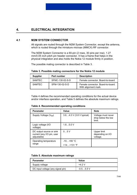
4. ELECTRICAL INTEGRATION4.1 M2M SYSTEM CONNECTORAll signals are routed through the M2M System Connector, except the antenna,which is routed through the miniature microax (MMCX) RF connector.The M2M System Connector is a 60-pin (2 rows, 30 pins per row), 1.27mm/0.05 inch pitch pin header connector. It has a frame that helps in thephysical integration and also holds the <strong>Nokia</strong> <strong>12</strong> module firmly in position.The possible mating connector is described in Table 3.Table 3. Possible mating connectors for the <strong>Nokia</strong> <strong>12</strong> moduleSupplier Part number DescriptionSAMTEC SFMC-130-02-S-D Female connector. Board-to-boardSAMTEC SFM-130-02-S-D Female connector. Board-to-board.With alignment mark.Table 4 defines the recommended operating conditions for the actual deviceand/or interface operation, and Table 5 defines the absolute maximum ratings.Table 4. Recommended operating conditionsParameter Value NoteSupply Voltage (V BB ) 3.6…4.0 V (3.8 V typical) Voltage must neverdrop below the lowlimit.Logic voltage (I/Ovoltage)DC output source or sinkcurrent (any I/O pin, useradjustable)Operating temperaturerange1.8…5.0 V0…5 V Upper limitdepending on I/Ovoltage.-10…+55 °C+14…+131 °FTable 5. Absolute maximum ratingsParameterSupply voltageDC input voltage (any signal pin)Value+4.2 V-0.5…5.5 V7/44