Nokia 12 GSM Module Hardware Integration ... - KORE Telematics
Nokia 12 GSM Module Hardware Integration ... - KORE Telematics
Nokia 12 GSM Module Hardware Integration ... - KORE Telematics

Create successful ePaper yourself
Turn your PDF publications into a flip-book with our unique Google optimized e-Paper software.
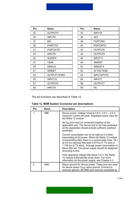
Pin Name Pin Name33 OUTPUT5 34 INPUT635 INPUT5 36 AD137 BSI 38 PORT2RX39 PORT2TX 40 PORT2RTS41 PORT2CTS 42 OUTPUT843 INPUT8 44 OUTPUT945 SLEEPX 46 INPUT1147 VSIM 48 SIMRST49 SIMCLK 50 SIMDATA51 SIMDET 52 IO VOLTAGE53 OUTPUT1/P3RX 54 INPUT4/P3TX55 INPUT10 56 INPUT757 OUTPUT6 58 OUTPUT759 INPUT9 60 NCThe pin functions are described in Table <strong>12</strong>.Table <strong>12</strong>. M2M System Connector pin descriptionsPin Name Description1 VBB Device power. Voltage nominal 3.8 V, 3.6 V – 4.0 V,maximum current 2A peak. Regulated power input forthe <strong>Nokia</strong> <strong>12</strong> module.All V BB pins must be connected together at theapplication end. The device end is not fuse-protected,so the application should provide sufficient overloadprotection.Current consumption can be as high as 2 A whentransmitting at full power. When the <strong>Nokia</strong> <strong>12</strong> moduleis transmitting data, there is a current peak (max. 2A )at 4.6 ms intervals that lasts 0.577ms (1 TX slot) or1.154 ms (2 TX slots). Average power consumption isabout 500 mA. The power supply should be designedaccording to this.If the operating voltage falls below 3.4 V, the <strong>Nokia</strong><strong>12</strong> module automatically shuts down. For moreinformation on the power supply, see Chapter 4.3.2 GND Return ground for device power. These pins are usedfor device power (V BB ) return ground. Connect tocommon ground. All GND pins must be connected at11/44