Nokia 12 GSM Module Hardware Integration ... - KORE Telematics
Nokia 12 GSM Module Hardware Integration ... - KORE Telematics
Nokia 12 GSM Module Hardware Integration ... - KORE Telematics

Create successful ePaper yourself
Turn your PDF publications into a flip-book with our unique Google optimized e-Paper software.
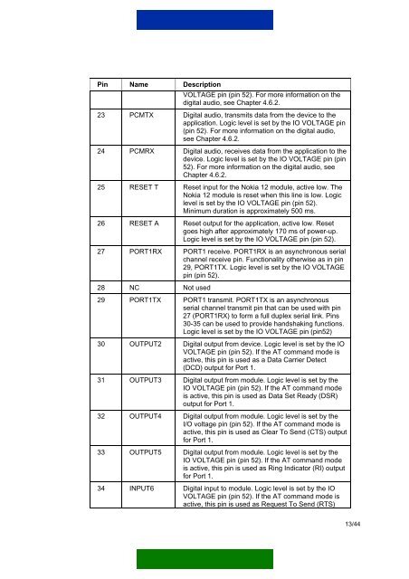
Pin Name DescriptionVOLTAGE pin (pin 52). For more information on thedigital audio, see Chapter 4.6.2.23 PCMTX Digital audio, transmits data from the device to theapplication. Logic level is set by the IO VOLTAGE pin(pin 52). For more information on the digital audio,see Chapter 4.6.2.24 PCMRX Digital audio, receives data from the application to thedevice. Logic level is set by the IO VOLTAGE pin (pin52). For more information on the digital audio, seeChapter 4.6.2.25 RESET T Reset input for the <strong>Nokia</strong> <strong>12</strong> module, active low. The<strong>Nokia</strong> <strong>12</strong> module is reset when this line is low. Logiclevel is set by the IO VOLTAGE pin (pin 52).Minimum duration is approximately 500 ms.26 RESET A Reset output for the application, active low. Resetgoes high after approximately 170 ms of power-up.Logic level is set by the IO VOLTAGE pin (pin 52).27 PORT1RX PORT1 receive. PORT1RX is an asynchronous serialchannel receive pin. Functionality otherwise as in pin29, PORT1TX. Logic level is set by the IO VOLTAGEpin (pin 52).28 NC Not used29 PORT1TX PORT1 transmit. PORT1TX is an asynchronousserial channel transmit pin that can be used with pin27 (PORT1RX) to form a full duplex serial link. Pins30-35 can be used to provide handshaking functions.Logic level is set by the IO VOLTAGE pin (pin52)30 OUTPUT2 Digital output from device. Logic level is set by the IOVOLTAGE pin (pin 52). If the AT command mode isactive, this pin is used as a Data Carrier Detect(DCD) output for Port 1.31 OUTPUT3 Digital output from module. Logic level is set by theIO VOLTAGE pin (pin 52). If the AT command modeis active, this pin is used as Data Set Ready (DSR)output for Port 1.32 OUTPUT4 Digital output from module. Logic level is set by theI/O voltage pin (pin 52). If the AT command mode isactive, this pin is used as Clear To Send (CTS) outputfor Port 1.33 OUTPUT5 Digital output from module. Logic level is set by theIO VOLTAGE pin (pin 52). If the AT command modeis active, this pin is used as Ring Indicator (RI) outputfor Port 1.34 INPUT6 Digital input to module. Logic level is set by the IOVOLTAGE pin (pin 52). If the AT command mode isactive, this pin is used as Request To Send (RTS)13/44