Nokia 12 GSM Module Hardware Integration ... - KORE Telematics
Nokia 12 GSM Module Hardware Integration ... - KORE Telematics
Nokia 12 GSM Module Hardware Integration ... - KORE Telematics

Create successful ePaper yourself
Turn your PDF publications into a flip-book with our unique Google optimized e-Paper software.
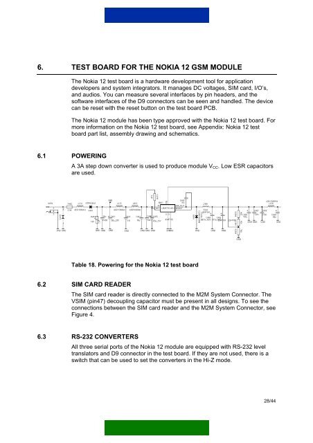
6. TEST BOARD FOR THE NOKIA <strong>12</strong> <strong>GSM</strong> MODULEThe <strong>Nokia</strong> <strong>12</strong> test board is a hardware development tool for applicationdevelopers and system integrators. It manages DC voltages, SIM card, I/O’s,and audios. You can measure several interfaces by pin headers, and thesoftware interfaces of the D9 connectors can be seen and handled. The devicecan be reset with the reset button on the test board PCB.The <strong>Nokia</strong> <strong>12</strong> module has been type approved with the <strong>Nokia</strong> <strong>12</strong> test board. Formore information on the <strong>Nokia</strong> <strong>12</strong> test board, see Appendix: <strong>Nokia</strong> <strong>12</strong> testboard part list, assembly drawing and schematics.6.1 POWERINGA 3A step down converter is used to produce module V CC . Low ESR capacitorsare used.Table 18. Powering for the <strong>Nokia</strong> <strong>12</strong> test board6.2 SIM CARD READERThe SIM card reader is directly connected to the M2M System Connector. TheVSIM (pin47) decoupling capacitor must be present in all designs. To see theconnections between the SIM card reader and the M2M System Connector, seeFigure 4.6.3 RS-232 CONVERTERSAll three serial ports of the <strong>Nokia</strong> <strong>12</strong> module are equipped with RS-232 leveltranslators and D9 connector in the test board. If they are not used, there is aswitch that can be used to set the converters in the Hi-Z mode.28/44