MME for Fanuc 6, 11, 12 Manual - Memex Automation
MME for Fanuc 6, 11, 12 Manual - Memex Automation
MME for Fanuc 6, 11, 12 Manual - Memex Automation

Create successful ePaper yourself
Turn your PDF publications into a flip-book with our unique Google optimized e-Paper software.
<strong>MME</strong>/HSL Memory Upgrade <strong>for</strong> <strong>Fanuc</strong> For Series 6, <strong>11</strong> & <strong>12</strong>Installation Instructionsand Operator’s <strong>Manual</strong>M100700D© 20<strong>12</strong> <strong>Memex</strong> <strong>Automation</strong> Inc. All rights reserved.No part of this manual may be reproduced without express written consent of <strong>Memex</strong> <strong>Automation</strong> Inc.<strong>Memex</strong> does not assume any liability <strong>for</strong> the use of this manual.
ContentsTable of ContentsChapter 1 – Introduction ........................................................................... 4General ..................................................................................................... 4Features .................................................................................................... 4Board Features Description ....................................................................... 5Chapter 2 - The Basics .............................................................................. 6Using Parameter Sentry System ............................................................... 6Installation Considerations ........................................................................ 7Backup Critical Parameters ....................................................................... 7Verify Your Control .................................................................................... 7Chapter 3 - Installation <strong>for</strong> <strong>Fanuc</strong> 6 ........................................................ 8Back Up Your Control ................................................................................ 8NC Parameters .................................................................. 8Pitch Error Compensation .................................................. 8Part Programs .................................................................... 9Tool Offsets ....................................................................... 9Work Offsets ...................................................................... 9PC Parameters ................................................................. 10System Parameters .......................................................... 10Setting Data ...................................................................... 10Quick-Load procedures <strong>for</strong> <strong>Fanuc</strong> 6 ....................................................... <strong>11</strong>Installation Checklist <strong>for</strong> <strong>Fanuc</strong> 6............................................................ 14Restoring Your <strong>Fanuc</strong> 6 ......................................................................... 15M100700DPage 2
ContentsChapter 4 - Installation <strong>for</strong> <strong>Fanuc</strong> <strong>11</strong>/<strong>12</strong> ................................................ 18Back Up Your Control .............................................................................. 18NC Parameters ................................................................. 18Pitch Error Compensation ................................................. 18Part Programs .................................................................. 19Tool Offsets ...................................................................... 19Macro Variables ................................................................ 19Quick-Load procedures <strong>for</strong> <strong>Fanuc</strong> <strong>11</strong>/<strong>12</strong> ................................................ 20<strong>Manual</strong> Installation Procedures <strong>for</strong> <strong>Fanuc</strong> <strong>11</strong>/<strong>12</strong> .................................... 23Installation Checklist <strong>for</strong> <strong>Fanuc</strong> <strong>11</strong>/<strong>12</strong> .................................................... 25Chapter 5 – Appendix ............................................................................... 26Technical Summary <strong>for</strong> <strong>Fanuc</strong> 6 ............................................................ 26Technical Summary <strong>for</strong> <strong>Fanuc</strong> <strong>11</strong>/<strong>12</strong> ..................................................... 28Parameter Worksheet .............................................................................. 30Specifications ........................................................................................... 33Standard ASCII Table .............................................................................. 34M100700DPage 3
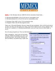
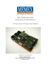
Chapter 1 - IntroductionBoard Features Description (<strong>Fanuc</strong> 6/<strong>11</strong>/<strong>12</strong> - 320M to <strong>12</strong>80M)2 541 3678<strong>11</strong>9101 CNC ConnectorPlugs into the BMU slot on the CNC2 CPU20 Mhz processor in socket3 Option JumpersUsed to select CNC type4 NVSRAM8K x 8 Non-Volatile SRAM <strong>for</strong> ParameterSentry System5 Serial PortHigh speed serial port <strong>for</strong> diagnostics6 BMU ConnectorUsed <strong>for</strong> quick-loading old BMU8 Status LEDsTurbo, Data Status, Quick Load, Saveand Restore9 Parameter Sentry SystemToggle switch & push button10 MOS ConnectorUsed <strong>for</strong> HSL upgrades<strong>11</strong> Perma-Charge BatteryRechargeable, Lithium batteryNote: 2 Megs on a <strong>Fanuc</strong> <strong>11</strong>/<strong>12</strong> uses HSL7 SRAM (1 – 4)<strong>12</strong>8K x 8 high speed, low powerM100700DPage 5
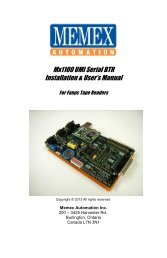
Chapter 2 – The BasicsThe BasicsUsing the Parameter Sentry SystemThe <strong>MME</strong>’s Parameter Sentry System is unique and simple to use. The system offersprotection of the first 20 meters (8K) of memory, thus protecting all of your NC systemparameters, PC parameters, Tool Offset data, Pitch Error Compensation data and Systemdata. Note that part programs are not included. The HSL saves the bottom <strong>12</strong>80 meters(5<strong>12</strong>k). All of these parameters are stored in Non-Volatile SRAM (NVSRAM). This memory isNon-Volatile meaning that it does not require a backup power source of any kind and is arelatively permanent and a convenient <strong>for</strong>m of storing your critical control parameters.To use the Parameter Sentry System, power on your <strong>Fanuc</strong> control and bring the CRT to thePosition screen. Open the control cabinet with the <strong>Fanuc</strong> control. Make sure that the powerremains ON when you open the door to the cabinet. While holding the toggle switch at thebottom of the <strong>Memex</strong> <strong>MME</strong> board toward the “SAVE” position, momentarily PUSH the “PARAMSENTRY” button, and then release the toggle switch. You should notice the LED adjacent tothe toggle switch light up <strong>for</strong> approximately one second. This will save your <strong>Fanuc</strong> systemparameters in the NOVRAM.To RESTORE your parameters, reverse the above procedure. Make sure that your <strong>Fanuc</strong>CNC is turned on and that you have access to the <strong>Memex</strong> <strong>MME</strong>. While holding the toggleswitch toward “RESTORE”, momentarily PUSH the “PARAM SENTRY” button, then releasethe toggle switch. Again, you should notice the “Restore” LED light up <strong>for</strong> one second. Poweroff your control, then power on again <strong>for</strong> the saved parameters to take effect.If an error relating to part programs occurs at this point after powering on the control, you mayalso need to Delete All Part Programs by powering on the control while holding theDELET & RESET keys.<strong>Memex</strong> HSL3 Board Used For <strong>Fanuc</strong><strong>11</strong> & <strong>12</strong> Upgrades to 2 MegsM100700DPage 6
Chapter 2 – The BasicsInstallation ConsiderationsThe installation of the <strong>MME</strong> should be conducted with care. Never install or remove a board withthe control power on (the main power can be on, but not the control). Take care with the handlingof the <strong>MME</strong> and BMU, as they are static sensitive. Keep the boards in the anti-static bagsprovided. Take care not to place the circuit boards on a metal surface as the backup battery couldsuffer damage if shorted. Do not place the <strong>MME</strong> in any other slot on the <strong>Fanuc</strong> master-board,other than the one, labeled BMU. Do not <strong>for</strong>ce, drop or otherwise mishandle the boards during theinstallation procedure. Always check the functionality of the machine at the end of the installation(i.e. move the axes, per<strong>for</strong>m a tool change, run a program, etc.).Backup Critical ParametersAlthough the <strong>MME</strong> has the ability to transfer the relevant NC parameters, it is a good idea tomake a manual backup of all in<strong>for</strong>mation in the BMU be<strong>for</strong>e proceeding (if possible). The <strong>MME</strong>will contain no useful in<strong>for</strong>mation when shipped, and as such the following data must be reloaded:NC parameters, PC parameters, tool offsets, part programs, macro variables and names (ifapplicable), etc. Follow your <strong>Fanuc</strong> manual <strong>for</strong> the appropriate procedure.Verify Your ControlOnce the <strong>MME</strong> has been installed either manually or by the Quick-Load method, satisfy yourselfthat the control is working properly and that all of your parameters have been restored.Test the machine by the following procedure through either MDI or program:Home all axes, tool-changers and pallets.Check spindle functionality through all speeds and gear ranges.Check also Clockwise and Counter-clockwise rotation with M3 and M4commands.Check the tool changer. Be sure that the tool you received was the toolrequested and that the carousel rotates in the proper direction.Check the pallet changer (if applicable). If your machine requires specialcustom macros <strong>for</strong> a pallet changer or tool changer, be sure that theyhave been loaded.Once your machine has been proven with the <strong>MME</strong>, you have successfully upgraded your control.M100700DPage 7
Chapter 3 – Installation <strong>for</strong> <strong>Fanuc</strong> 6Installation <strong>for</strong> <strong>Fanuc</strong> 6Backup Your ControlBe<strong>for</strong>e starting the installation, power on the control and verify that the machine tool is in goodworking order. If the control has a system error, or the BMU is inoperable, you will have to replaceyour memory board with the <strong>MME</strong>, and restore the in<strong>for</strong>mation from existing backup sources.Important!Backup the following BMU memory contents: NC parameters, PC Parameters(if parameter 3.7 = 1), Tool Offsets, Pitch Error Compensation, and PartPrograms (if applicable). All of this in<strong>for</strong>mation is contained in the BubbleMemory Unit (BMU) and must be restored; there<strong>for</strong>e all of this in<strong>for</strong>mationmust either be written down or punched out of the control via the RS-232serial port. Use the “<strong>Fanuc</strong> System 6 Machine Parameter Worksheet”provided at the end of this document to record the important parameter data.Use the following procedures to save the data on a computer. If in doubt,consult your <strong>Fanuc</strong> manuals, as they are your ultimate authority on yourparticular version of control.1. Set up your computer to receive data through its COM port and connect itto your <strong>Fanuc</strong> control. Set the communication parameters on your PC <strong>for</strong>7 data bits, and the stop bits and baud rate as determined by theapplicable parameters <strong>for</strong> your control. Please refer to the “<strong>Fanuc</strong> 6Technical Summary” at the end of this document <strong>for</strong> the appropriateparameters.NC Parameters2. Make the computer ready to receive the data. Select EDIT Mode.Press the PARAM key to display the Parameter Screen. Press P - 9 9 9 9 PUNCHThe Parameters will be punched out.Pitch ErrorCompensation3. Make the computer ready to receive the Pitch Error data. Confirm that EDIT Mode is selected. Confirm the Parameters are displayed on the screen. Press P - 9 9 9 8 PUNCHThe Pitch Error data will be punched out.M100700DPage 8
Chapter 3 – Installation <strong>for</strong> <strong>Fanuc</strong> 6Part Programs4. NOTE: Any macro programs in the range of O8000-O9999 that have beenprotected from editing will not be transferred. Release the parameter bitsthat are protecting them. On a <strong>Fanuc</strong> 6-B2, one would go through thefollowing steps:To release the Macro Program “Edit Protect” on a <strong>Fanuc</strong> 6-B2:- Select MDI Mode.- Switch the Parameter Write switch to the ON position (ignore thePW100 alarm).- Press the PARAM key to display the Parameter Screen.- Set parameter 319 bit 7 and 318 bit 7 (left most digit) to a 0 (zero).- Switch PWE to the OFF position.- Press RESET to clear the PW100 alarm.Make the computer ready to receive the programs. Select EDIT Mode.Press PRGRM to display the Program Screen. Press O - 9 9 9 9 PUNCHAll of the programs will be punched out.Tool Offsets5. Make the computer ready to receive the Tool Offset data. Confirm that EDIT Mode is selected.Press OFSET to display the Tool Offset Screen. Press P - 9 9 9 9 PUNCHThe Tool Offsets will be punched out.Work Offsets6. Press OFSET again to display the Work Offset Screen. If it does notappear, you do not have any Work Offsets in your machineproceed tothe next step.If you do have a Work Offset screen, record the Work Offsets in thefollowing chart:Relative 00 01 02 03XYZRelative 04 05 06XYZM100700DPage 9
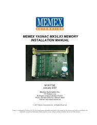
Chapter 3 – Installation <strong>for</strong> <strong>Fanuc</strong> 6PC Parameters7. Check Parameter 3, bit 7. If this is a 0, go to step #8 (System Parameters)as you have no PC Parameters. Write down the PC Parameters between,and including the following parameters: N600-619, N1001-1040, N2001-2010 and N3001-3036.Press the PARAM key twice to display the PC Parameter Screen. Type N 6 0 0 INPUT to select PC Parameter 600.You can use the (cursor) key to advance the PC Parameternumber.Write down the PC Parameter values on the Parameter chart found inthe back of this manual.Repeat the last two lines to record the remaining PC Parameters.SystemParameters8. Press the PARAM key once again to display the Parameter Screen. Type N 0 INPUT to select Parameter 0. You can use the (cursor) key to advance the Parameter number. Write down the System Parameter values on the Machine ParameterWorksheet found at the end of this manual. Repeat the last two lines to record the remaining Parameters.Setting Data9. Press the SET key to display the Setting Data Screen.Record all of the Setting Data on the Parameter Worksheet found inthe Appendix of this manual.<strong>Fanuc</strong> 6-TB Control – <strong>Memex</strong> Also Makes BTRs For Serial DripfeedingM100700DPage 10
Chapter 3 – Installation <strong>for</strong> <strong>Fanuc</strong> 6Quick-Load Procedures <strong>for</strong> <strong>Fanuc</strong> 6Time Needed: 1 hour (approx.)Tools Needed: 1 Philips ScrewdriverComponents: 1 <strong>MME</strong> memory boardControls: <strong>Fanuc</strong> 6A, 6B and 6-B2Be<strong>for</strong>e starting the installation, power on the control and verify that the machine tool is in goodworking order.Important!Make sure that you have a current backup of the NC parameters, includingPC Parameters, Tool Offsets, Pitch Error Compensation, and Part Programs.For instructions on downloading your control’s in<strong>for</strong>mation, refer to previoussection entitled “Backup Your Control” at the beginning of Chapter 3.1. Inspect the <strong>Memex</strong> Memory Engine (<strong>MME</strong>) <strong>for</strong> any damage duringshipping. Also check that the “CNC Type” jumpers have been set to the<strong>Fanuc</strong> 6 control type.Remove theBubble memoryInstall the <strong>MME</strong>memory2. With the <strong>Fanuc</strong> control powered off and the Emergency Stop (E-STOP)button depressed, gain access to the main master-board. Find the BubbleMemory Unit (BMU) board on the right-hand side of the master-board, andcarefully remove it with a Philips screwdriver. Carefully place the BMU inthe anti-static box supplied, and set it aside.3. Install the <strong>MME</strong> in the slot where the BMU was removed once again usingthe Philips screwdriver.4. Locate the Parameter Write Enable (PWE) switch on the lower left of themaster-board. Move the switch to the right to the “ON” (enable) position.CAUTION!5. With the 0 (zero) and DEL “DELETE” keys depressed on the frontMDI panel, power on the control. This action will cause the control to startupand immediately clear the entire memory of the <strong>MME</strong>. If the control willnot power on at this point, check that the cabinet door interlock isbypassed. The control may take a few seconds to clear the entirememory. You will then be given a “WARNING: SYSTEMINCONSISTENT” alarm and will be prompted to press RESET tocontinue. Ignore this “Reset” prompt.6. Power off the control.M100700DPage <strong>11</strong>
Chapter 3 – Installation <strong>for</strong> <strong>Fanuc</strong> 67. Restore the PWE switch to the “OFF”, or disabled, position.<strong>MME</strong>Quickload!8. Mount the original BMU onto the blue “BMU” connector found on the <strong>MME</strong>board. Screw down the top screw into the <strong>MME</strong> to secure the BMUproperly.Copy the Data9. Power on the control with the door interlock disabled. The control shouldstart-up normally from the original BMU. During this boot up process,parameter data is being relocated to the appropriate memory areas in the<strong>MME</strong>. To ensure a complete transfer, view the parameter screen, pagethrough all the tool offsets, etc. If all looks normal, release theEMERGENCY STOP (E-STOP) button.10. Power off the control and carefully remove the BMU. Set the BMU aside inthe anti-static bag provided.Check theParameters<strong>11</strong>. Power the control on holding DELET and RESET . It should start-upand arrive at the position screen. Check all your parameters, tool offsetsetc., carefully. Note that Part Programs do not get Quick-loaded at thistime. At the program screen, in EDIT mode, view the directory by pressingCAN then ORIGIN . This will verify the available memory in the new<strong>MME</strong>.<strong>12</strong>. Initiate a Parameter Sentry “SAVE” operation to save your parameters tonon-volatile memory. It is best to do this when there are no part programspresent as the directory that is saved should be clear of entries.13. Test your machine thoroughly. You can proceed to the section of this manual entitled“Verify Your Control” <strong>for</strong> assistance.M100700DPage <strong>12</strong>
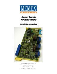
Chapter 3 – Installation <strong>for</strong> <strong>Fanuc</strong> 6<strong>MME</strong> Quickload on a <strong>Fanuc</strong> 6M100700DPage 13
Chapter 3 – Installation <strong>for</strong> <strong>Fanuc</strong> 6Installation Checklist <strong>for</strong> <strong>Fanuc</strong> 6 Check Machine - Power On - Check <strong>for</strong> Machine Problems Be<strong>for</strong>e You Start. Backup Parameters and Programs. Power Off. Depress E-STOP Remove BMU and set it aside. Mount <strong>MME</strong>. Set PWE to enable. Power On the Control with 0 and DEL depressed, to erase <strong>MME</strong>. Power Off and turn PWE off. Piggy-Back BMU to <strong>MME</strong> - Secure with Screw. Power Up - Page through the Tool Offsets. Power Off. Remove BMU. Power On while holding DELET and RESET . Check the Parameters and machine operation thoroughly. Save your parameters with the Parameter Sentry Save. Complete.M100700DPage 14
Chapter 3 – Installation <strong>for</strong> <strong>Fanuc</strong> 6Restoring your <strong>Fanuc</strong> 6If you have successfully installed your <strong>MME</strong> via the Quick-Load method described in theprevious section, then skip this chapter. This chapter is designed to step you through a manualBMU restore operation with the assumption that you have adequate backups.CAUTION!1. Open the door to the control’s master-board on your machine. Replace the BMU with your new memory board. Turn ON (Enable) the Parameter Write switch located in the lower leftcorner of the control’s master-board (ignore the PW100 alarm).Power ON the control while holding both the 0 (zero) and DELETkeys. This will delete the entire memory board in your control!Wait <strong>for</strong> the control to completely erase your new memory board. Itwill be done when you get the “System Inconsistent” message.2. Set up your computer to send data through the COM port and connect it toyour <strong>Fanuc</strong> control.Press the PARAM key to display the Parameter Screen. Type N 3 1 0 INPUT to select Parameter 310.You can use the (cursor) key to advance the Parameternumber.Set the communication parameters by pressing P , the originalvalue, then INPUT .Repeat the last two lines to enter all the system parameters that youhad previously recorded.3. Power OFF the control, then power it back ON.LoadingNC Parameters4. Make the computer ready to send the Parameter data to the control. Select EDIT Mode. Press the EMERGENCY STOP button in. Press the SET key to display the display Setting Screen. Restore the correct Setting in<strong>for</strong>mation from your backup. Confirm that the Parameter Write switch is in the ENABLE position. Press the PARAM key to display the Parameter Screen. Press P - 9 9 9 9 READ Send the (backed-up) Parameters to the control from your computer.M100700DPage 15
Chapter 3 – Installation <strong>for</strong> <strong>Fanuc</strong> 6Pitch ErrorCompensation5. Make the computer ready to send the Pitch Error data to the control. Confirm the EMERGENCY STOP button has been depressed. Confirm that the Parameter Write switch is in the ENABLE position. Confirm the Parameters are displayed on the screen. Press P - 9 9 9 8 READ Send the Pitch Error data file to the control from your computer.6. Power OFF the control, then power it back ON.PC Parameters7. If Parameter 3, bit 7 was a 0, then skip this step; otherwise: Confirm that the EMERGENCY STOP button is in. Confirm that the Parameter Write switch is in the ENABLE position. Press the PARAM key twice to display the PC Parameter Screen. Type N 6 0 0 INPUT to select PC Parameter 600. You canuse the (cursor) key to advance the PC Parameter number and (page down) to view a page worth of PC Parameters.Set the PC Parameters by pressing P , the original value, thenINPUT .Repeat the last two lines to enter all the remaining PC Parametersthat you recorded.Program DataInput Option8. Press the PARAM key to display the Parameter Screen. Type N 3 INPUT to select System Parameter 3. Check that bit 1 (2 nd from right), of System Parameter 3 is a 1. If it isnot, set it to a 1 by pressing P , the new value, then INPUT .Reset theControl9. Power OFF the control. Turn OFF (Disable) the Parameter Write switch on the master-board. Release the EMERGENCY STOP. Power the control back ON.M100700DPage 16
Chapter 3 – Installation <strong>for</strong> <strong>Fanuc</strong> 6LoadingTool Offsets10. Make the computer ready to send the Offset file. Confirm that the control is in EDIT Mode. Confirm that the Program Screen in showing. Press O 0 0 0 1 , then READ Send the Tool Offset file to the control from your computer. The Tool Offsets will be loaded into the control as program O0001.Once the file has been sent, press RESET . Put the control in MEM Mode, then press CYCLE START . Press the OFSET key to display the Tool Offsets. Verify that all of the Tool Offsets have been loaded successfully.If not, reload the Tool Offsets manually as necessary. If all of the Tool Offsets have been reloaded successfully, deleteprogram 1 by pressing O 0 0 0 1 , then DELET .LoadingPart Programs<strong>11</strong>. Any macro programs that have been protected from editing will not beloaded. On a <strong>Fanuc</strong> 6-B, check that parameters 318 and 319 have bit 7equal 0. To release the Macro Program “Edit Protect” on a <strong>Fanuc</strong> 6-B:- Select MDI Mode.- Switch PWE to the ON position (ignore the PW100 alarm).- Press the PARAM key to display the Parameter Screen.- Set parameter 319 bit 7 and 318 bit 7 (left most digit) to a 0 (zero).- Switch PWE to the OFF position.- Press RESET to clear the PW100 alarm.Make the computer ready to send the program file.Press PRGRM to display the Program Screen. Press O - 9 9 9 9 READSend the programs to the control from your computer.<strong>12</strong>. If the programs were protected, restore parameters 318 and 319 to theiroriginal values.13. Press the OFSET key and restore the Work Zero offsets.M100700DPage 17
Chapter 4 – Installation <strong>for</strong> <strong>Fanuc</strong> <strong>11</strong>/<strong>12</strong>Installation <strong>for</strong> <strong>Fanuc</strong> <strong>11</strong>/<strong>12</strong>Backup Your ControlBe<strong>for</strong>e starting the installation, power on the control and verify that the machine tool is in goodworking order. If the control has a system error, or the BMU is inoperable, you will have to replaceyour memory board with the <strong>MME</strong>, and restore the in<strong>for</strong>mation from existing backup sources.Important!Be sure to write down the NC (Service) parameters; 0, 3, 20-23, 5001-5<strong>12</strong>2,9000 and 9100-9<strong>12</strong>5/9131/9207 (depending on you control). Backup theSetting Screen Data, NC parameters, PC parameters (Timers, Counters,Keep Relays, Data Tables and Position Module In<strong>for</strong>mation) and ToolOffsets. Use the “<strong>Fanuc</strong> System 10/<strong>11</strong>/<strong>12</strong> Machine Parameters” worksheetprovided at the end of this document to record important parameter data.Use the following procedures to save the data on a computer. If in doubtconsult your <strong>Fanuc</strong> manuals, as they are the ultimate authority on yourparticular control.1. Set up your computer to receive data through its COM port and connect itto your <strong>Fanuc</strong> control. Set the communication parameters on your PC <strong>for</strong>7 data bits, and the stop bits and baud rate as determined by theapplicable parameters <strong>for</strong> your control. Please refer to the “<strong>Fanuc</strong> 6Technical Summary” at the end of this document <strong>for</strong> the appropriateparameters.NC Parameters2. Make the computer ready to receive the data. Select EDIT mode.Press the SERVICE function key.Press PUNCH + PARAM (or ALL <strong>for</strong> Both NC + Pitche Error)The Parameters will be punched out.Pitch ErrorCompensation3. Make the computer ready to receive the Pitch Error data. Confirm that EDIT Mode is still selected.Press the SERVICE function key.Press PUNCH + PITCHThe Pitch Error data will be punched out.M100700DPage 18
Chapter 4 – Installation <strong>for</strong> <strong>Fanuc</strong> <strong>11</strong>/<strong>12</strong>Part Programs4. NOTE: Be<strong>for</strong>e backing up the Part Programs, check to see if there areany programs listed in the 8000’s or 9000’s. If there are, make sure theProgram Protect Parameter, NC parameter 2201--bit 0, must be a 0 <strong>for</strong>the 9000 series part-programs and parameter <strong>11</strong>--bit 0 must be a 0 <strong>for</strong> the8000 series programs. This will allow ALL part-programs, macros andcommon variables (in the Setting Screen) to be properly outputMake the computer ready to receive the programs. Select EDIT Mode.Press the PRGRM function key.Press PUNCH + ALLAll of the programs will be punched out.Tool Offsets5. Make the computer ready to receive the Tool Offset data. Confirm that EDIT Mode is selected.Press the OFFSET function key.Press PUNCH + TOOLThe Tool Offsets will be punched out.MacroVariables6. Punch out an MACRO (500 and above) variables if present as well.<strong>Fanuc</strong> <strong>11</strong> Quickload – BMU Mounted on <strong>MME</strong> in Slot Next to Power SupplyM100700DPage 19
Chapter 4 – Installation <strong>for</strong> <strong>Fanuc</strong> <strong>11</strong>/<strong>12</strong>Quick-Load Procedures <strong>for</strong> <strong>Fanuc</strong> <strong>11</strong>/<strong>12</strong>Time Needed: 1 hour (approx.)Tools Needed: 1 Philips ScrewdriverComponents: 1 <strong>MME</strong> memory boardControl: <strong>Fanuc</strong> <strong>11</strong>A, <strong>11</strong>B and <strong>12</strong>Be<strong>for</strong>e starting the installation, power on the control and verify that the machine tool is in goodworking order.Important!Make sure that you have a current backup of the NC parameters, ToolOffsets, Pitch Error Compensation, and Part Programs. For instructions ondownloading your control’s in<strong>for</strong>mation, refer to previous section entitled“Backup Your Control”.1. Inspect the <strong>Memex</strong> Memory Engine (<strong>MME</strong>) <strong>for</strong> any damage duringshipping. Also check that the “CNC Type” jumpers have been set to either<strong>Fanuc</strong> <strong>11</strong> or <strong>12</strong>.Remove theBubble memoryInstall the <strong>MME</strong>memory.2. With the <strong>Fanuc</strong> control powered off and the Emergency Stop (E-STOP)button depressed, gain access to the main masterboard. Find the BubbleMemory Unit (BMU) board on the right-hand side of the masterboard, andcarefully remove it with a Philips screw driver. Carefully place the BMU inthe anti-static box supplied, and set it aside.3. Install the <strong>MME</strong> in the slot where the BMU was removed once again usingthe Philips screwdriver.CAUTION!4. With the 7 + 9 keys depressed on the front MDI panel, power on thecontrol. This action will cause the control to start-up and immediatelyclear the entire memory of the <strong>MME</strong>. If the control will not power on atthis point, check that the cabinet door interlock is bypassed. When thecontrol powers on, it will eventually show the IPL Screen.5. Power off the control.<strong>MME</strong>Quickload!6. Mount the original BMU onto the blue “BMU” connector found on the <strong>MME</strong>board. Screw down the top screw into the <strong>MME</strong> to secure the BMUproperly.M100700DPage 20
Chapter 4 – Installation <strong>for</strong> <strong>Fanuc</strong> <strong>11</strong>/<strong>12</strong>Copy the Data7. Power on the control. It should start-up normally with the original BMU incontrol. During this process parameter data is being relocated to theappropriate memory areas in the <strong>MME</strong>. To ensure a complete transfer,view the parameter screen, tool offset screen, part program screen,…etc.If it all looks normal, release the E-STOP button.8. Power off the control and carefully remove the BMU. Set the BMU aside inthe anti-static bag provided.Check theParameters9. Power the control and check the functionality of the machine at this point.Re-Zero the axes, test the spindle, test the tool changing mechanism (besure you get the tool you request and that it goes into the correct pocket),check out any pallet changers and other peripherals.Caution: Keep your rapid and feed rate overrides low. The machine maynot behave the way you might expect it to. If abnormalities in the operationare noticed, check all of the system parameters in case they may not havebeen properly restored by the Quick-Load (if so go to step 14).10. Initiate a Parameter Sentry “SAVE” operation to save your parameters tonon-volatile memory. It is best to do this when there are no part programspresent as the directory that is saved should be clear of entries. (Note thatpowering on in IPL mode and clearing files “3 INPUT”, then “7input” isneeded)<strong>11</strong>. Test your machine thoroughly. You can proceed to the section of thismanual entitled “Verify Your Control” <strong>for</strong> assistance.You are done…<strong>12</strong>. If an error has occurred during the installation of your <strong>MME</strong> it is possiblean alternative method may have to be used. Follow steps 1 through 4 asper the above directions but be<strong>for</strong>e continuing with step 5 complete thefollowing extra steps.13. Remove the Option Jumper #2 on the <strong>MME</strong> board. This will limit theParameter Sentry system to protecting the System Label only. Followingare the steps required to correctly write the System Label. After you followthrough with the remainder of the Quick-Load procedure, you will have torestore the over-written System Label with backed up version that isguarded by Parameter Sentry.14. With the . + - keys depressed on the front MDI panel, power on thecontrol. When the control powers on it will eventually show the IPL ScreenM100700DPage 21
Chapter 4 – Installation <strong>for</strong> <strong>Fanuc</strong> <strong>11</strong>/<strong>12</strong>15. At the prompt, you will enter 9 9 then INPUT . Use the inputbutton to the right of the MDI keypad.16. Press Y to initialize the system label.17. Enter the number you wrote down from parameter 9000 on the parametersheet, <strong>for</strong> the No. of Axes. Beginning with parameter 9100, enter the HEXvalue of each parameter <strong>for</strong> the option numbers that need to be entered. Ifyou incorrectly enter a number at this point, you will have to press INPUTthrough the remaining Options, then go back and begin the process again.18. When you reach the end press Y to clear the files.19. Go back to the IPL menu and press 6 to End IPL. If you should get anyalarm in the 900’s, call our toll free tech support line.20. At this point initiate a Parameter Sentry save by moving the toggle switchon the right side of the <strong>MME</strong> towards the SAVE position, then pressing thePush Button. The SAVE light should momentarily light up. See Using the<strong>MME</strong> Parameter Sentry System <strong>for</strong> more detail.21. Complete steps 8 through 10 above then continue. Once the followingsteps have been completed continue with <strong>11</strong> to 13 above.22. Power on the control while holding . + - . This will again get you intothe IPL screen.23. Initiate a Parameter Sentry restore operation by moving the toggle switchon the right side of the <strong>MME</strong> towards the RESTORE position, thenpressing the Push Button. The RESTORE light beside the toggle switchshould momentarily light up.24. Power off the control, then replace Option Jumper #2 on the <strong>MME</strong>.(continue with step 6 to <strong>11</strong> as per above in this section)M100700DPage 22
Chapter 4 – Installation <strong>for</strong> <strong>Fanuc</strong> <strong>11</strong>/<strong>12</strong><strong>Manual</strong> Installation Procedures <strong>for</strong> <strong>Fanuc</strong> <strong>11</strong>/<strong>12</strong>Time Needed: 2 hours (approx.)Tools Needed: 1 Philips ScrewdriverComponents: 1 <strong>MME</strong> memory boardControls: <strong>Fanuc</strong> <strong>11</strong>A, <strong>11</strong>B and <strong>12</strong>Be<strong>for</strong>e starting the installation, power on the control and verify that the machine tool is in goodworking order.Important!Make sure that you have a current backup of the NC parameters, ToolOffsets, Pitch Error Compensation, and Part Programs. For instructions ondownloading your control’s in<strong>for</strong>mation, refer to previous section entitled“Backup Your Control”.1. Inspect the <strong>Memex</strong> Memory Engine (<strong>MME</strong>) <strong>for</strong> any damage duringshipping. Also check that the “CNC Type” jumpers have been set to eitherthe <strong>Fanuc</strong> <strong>11</strong> or <strong>12</strong> (depending on control type).Remove theBubble memoryInstall the <strong>MME</strong>memory.2. With the <strong>Fanuc</strong> control powered off and the Emergency Stop (E-STOP)button depressed, gain access to the main masterboard. Find the BubbleMemory Unit (BMU) board on the right-hand side of the masterboard, andcarefully remove it with a Philips screw driver. Carefully place the BMU inthe anti-static box supplied, and set it aside.3. Install the <strong>MME</strong> in the slot where the BMU was removed once again usingthe Philips screwdriver.CAUTION!4. With the 7 + 9 keys depressed on the front MDI panel, power on thecontrol. This action will cause the control to start-up and immediatelyclear the entire memory of the <strong>MME</strong>. If the control will not power on atthis point, check that the cabinet door interlock is bypassed. When thecontrol powers on, it will eventually show the IPL Screen.5. At the prompt, you will enter 9 9 then INPUT . Use the inputbutton to the right of the MDI keypad.6. Press Y to initialize the system label.M100700DPage 23
Chapter 4 – Installation <strong>for</strong> <strong>Fanuc</strong> <strong>11</strong>/<strong>12</strong>7. Enter the number you wrote down from parameter 9000 on the parametersheet, <strong>for</strong> the No. of Axes. Beginning with parameter 9100, enter the HEXvalue of each parameter <strong>for</strong> the option numbers that need to be entered. Ifyou incorrectly enter a number at this point, you will have to press INPUTthrough the remaining Options, then go back and begin the process again.8. When you reach the end press Y to clear the files.9. Go back to the IPL menu and press 6 to End IPL. If you should get anyalarm in the 900’s, call our toll free tech support line.10. Locate the Parameter Write Enable (PWE), parameter 8000 in theSettings (service) Screen, and change it to a 1 to enable PWE in MDImode.<strong>11</strong>. Now serially reload the remaining parameters or if need be re-enter theseby hand from your parameter tape, list, or backup.<strong>12</strong>. Once the NC parameters are reloaded, power off the control then power iton again. Turn on the PWE parameter again (8000), then press theNC/PC button and reload all of the PC parameters. When you areconfident that all of the parameters are correct, turn off the power.13. Power on the control and release the E-Stop. The control should start-upnormally. Check the functionality of the machine at this point. Re-zero theaxes, test the spindle, test the tool changing mechanism, check out anypallet changers and any peripherals.14. Once the machine has been proven, now would be a good time to do aParameter Sentry save. This will save a backup copy of all your criticalmachine parameters. Refer to the Using the parameter Sentry Systemsheet <strong>for</strong> more detailed instructions.15. Now reload your Programs and Tool Offset data, your control should befully operational, with the enhanced per<strong>for</strong>mance of the <strong>MME</strong>.M100700DPage 24
Chapter 4 – Installation <strong>for</strong> <strong>Fanuc</strong> <strong>11</strong>/<strong>12</strong>Installation Checklist <strong>for</strong> <strong>Fanuc</strong> <strong>11</strong>/<strong>12</strong> Check Machine - Power On - Check <strong>for</strong> Machine Problems Be<strong>for</strong>e You Start. Backup Parameters and Programs. Power Off. Depress E-STOP Mount <strong>MME</strong>. Power On the Control with 7 + 9depressed, to erase <strong>MME</strong>. Enter 9 9 in IPL menu. Enter the Number of axes and all of the Option data. Press 6 to End IPL . Set PWE then restore the base Service Parameters. Reload the remaining NC Parameters. Power OFF then ON. Set PWE, then reload the PC Parameters. Add in any MACRO Variables, tool offsets orMACRO part programs if needed. Power OFF then ON. Check parameters and machine operation thoroughly. At this complete state, you can optionally save your parameters with the on-board ParameterSentry System “save” feature. Complete.M100700DPage 25
Chapter 5 – AppendixAppendixTechnical Summary <strong>for</strong> <strong>Fanuc</strong> 6PUNCHING:Punch NC Parameters - EDIT mode, PARAM screen, key “P-9999”, PunchPunch Pitch Error Compensation - EDIT mode, PARAM screen, key “P-9998”, PunchPunch All Programs - EDIT mode, PGRM screen, key “O-9999”, PunchTool Offsets - EDIT mode, OFSET screen, key “P-9999”, PunchREADING:Load NC Parameters - EDIT, E-Stop, PWE, PARAM screen, key “P-9999”, ReadLoad Pitch Error Compensation - EDIT, E-Stop, PWE, PARAM screen, key “P-9998”, ReadLoad All Programs - EDIT mode, PGRM screen, Mem. Protect Key, key “O-9999”, ReadCLEARING:Delete Directory and Programs - Power On holding “RESET” + “DELETE”Delete Entire BMU - PWE enabled, Power On holding “0”+”DELETE”<strong>Fanuc</strong> 6AMasterboard: A20B-0007-0010 Software: 99x Maximum Memory: 320 MetersParameter Function Description2.5 1= punch 0=no punch Punch Option Enable7.7 1=LF,CR,CR 0=CR,LF End of line on punch9.1 1=ISO 0=EIA Format (choose ISO)24.0 1=2 0=1 Stop Bits25 9600 = <strong>11</strong><strong>11</strong> <strong>11</strong><strong>11</strong> Baud Rate <strong>for</strong> Serial Port4800 = <strong>11</strong>10 <strong>11</strong><strong>11</strong>2400 = <strong>11</strong>00 <strong>11</strong><strong>11</strong><strong>12</strong>00 = <strong>11</strong>00 <strong>11</strong>10600 = <strong>11</strong>00 <strong>11</strong>00300 = 1000 <strong>11</strong>00<strong>Fanuc</strong> 6B (early version)Masterboard: A20B-0008-0410Software: 900 Level Maximum Memory: 320 Meters (<strong>12</strong>8k)901/06 or later <strong>12</strong>80 Meters (5<strong>12</strong>k)902/06 or later <strong>12</strong>80 Meters (5<strong>12</strong>k)Parameter (.bit) FunctionDescription2.5 1= punch 0=no punch Punch Option Enable3.3 1=ISO 0=EIA Format (choose ISO)7.7 1=LF,CR,CR 0=CR,LF End of line on punch310-313.4 1=2 0=1 Stop Bits (leave at 0 - <strong>for</strong> standard <strong>Fanuc</strong> E-7-1)310-313.5 1=Not Used 0=DC Codes Software handshaking (leave at 0 <strong>for</strong> serial)310-313.7 1=Tape Feed 0=No Feed Punches tape feed at start of file (leave at 0)M100700DPage 26
Chapter 5 – AppendixParameter Function Description310-313.0-3 9600 = xxxx 1010 Baud Rate <strong>for</strong> Serial Port <strong>for</strong> <strong>Fanuc</strong> 6B4800 = xxxx 100<strong>12</strong>400 = xxxx 1000<strong>12</strong>00 = xxxx 0<strong>11</strong>1600 = xxxx 0<strong>11</strong>0300 = xxxx 0101318.7 1=Not Editable 0=Editable Protect 9000 series programs from editing319.7 1=Not editable 0=Editable Protect 8000 series programs from editing340 2=Serial Input Device Select341 2=Serial Output Device Select<strong>Fanuc</strong> 6-B2 (or <strong>Fanuc</strong> 6B Level 2)Masterboard: A16B-1000-0030Software Versions:(Power up in E-Stop to check software version)320 Meters Memory Maximum -Mxx (06, 14, 15, 16, 21, 22, 25, 26, 27, 28, 30, 31, 33 Ver 06, 35, 40, 42,44, 46, 81, 83 & 85)<strong>12</strong>80 Meter Maximum -Mxx (01 to 05, 07 to <strong>12</strong>, 33, 37, 39, 45, 1A to 1D, 47 to 7C, 87 to F3)Standard <strong>Fanuc</strong> Serial Port: (DB-25 Female)1 = Frame Ground 6 = Data Set Ready2 = Transmit Data 7 = Signal Ground3 = Receive Data 8 = Carrier Detect4 = Ready To Send 20= Error (Data Terminal Ready)5 = Clear To Send 25= +24 VoltsThe usual software handshaking cable configuration has 2,3 & 7 connected through, with 4&5 jumpered (hardwarehandshake lines) and pins 6,8 & 20 jumpered on the <strong>Fanuc</strong> side only.Bubble Memory Board Sizes (<strong>for</strong> all):A87L-0001-0015 20 M 8 KA87L-0001-0016 40 M 16 KA87L-0001-0017 80 M 32 KA87L-0001-0105 80 M 32 KA87L-0001-0018 320 M <strong>12</strong>8 KA87L-0001-0084 320 M <strong>12</strong>8 KA87L-0001-0085 640 M 256 KA87L-0001-0086 <strong>12</strong>80 M 5<strong>12</strong> KRemember to check SETTING Screen Data. Tool Offsets can be downloaded but the G10/G<strong>11</strong> option must be enabled(set parameter 3.1 to a 1) to reloaded them. They are loaded serially into program memory, then executed like a regularPart Program.NOTE: Parameters are listed as “P” “number.bit” (e.g. P 2 bit 5 is P2=xx1x xxxx)M100700DPage 27
Chapter 5 – AppendixTechnical Summary <strong>for</strong> <strong>Fanuc</strong> <strong>11</strong>/<strong>12</strong>PUNCHING:Punch NC Parameters - EDIT mode, SERVICE screen, key PUNCH - ALLPunch Pitch Error Compensation - EDIT mode, SERVICE screen, key PUNCH - PITCHPunch All Programs - EDIT mode, PRGRM screen, key PUNCH - ALLTool Offsets - EDIT mode, OFFSET screen, key PUNCH - TOOLREADING:Load NC Parameters - EDIT, E-Stop, PWE, PARAM screen, key READ - ALLLoad Pitch Error Compensation - EDIT, E-Stop, PWE, PARAM screen, key READ - PITCHLoad All Programs - EDIT mode, PGRM screen, Mem. Protect Key, key READ - ALLCLEARING:Delete Directory and Programs - EDIT mode, PRGRM screen, key DELETE - PROGRAM - ALLDelete Entire BMU - PWE enabled, Power On holding “7” + “9”<strong>Fanuc</strong> <strong>11</strong>AMasterboard: A20B-0007-0010 Software: 99xMaximum Memory: 320 MetresParameter Function Description0.2 1=Without 0=With Parity Bit0.3 1=LF 0=LF,CR,CR End of line on punch0.4 1=EIA 0=ISO Punch Code Format (choose ISO)See parameters 5<strong>11</strong>1 and 5<strong>11</strong>2 <strong>for</strong> STOP BITS and BAUD RATE in<strong>for</strong>mation.20 Input device interface number <strong>for</strong> <strong>for</strong>eground0: Tape Reader1: RS-232-C interface <strong>12</strong>: RS-232-C interface 23: RS-232-C interface 310: Remote (DNC)<strong>11</strong>: 20mA current type interface (ASR33, ASR44)13: RS-422 interface21 Output device interface number <strong>for</strong> <strong>for</strong>eground(Same as 20 except no Tape Reader option)22 Input device interface number <strong>for</strong> background(Same as 20)23 Output device interface number <strong>for</strong> background(Same as 20 except no Tape Reader option)5001 I/O device No. to be connected to RS232C interface 15002 I/O device No. to be connected to RS232C interface 25003 I/O device No. to be connected to RS232C interface 350<strong>11</strong> I/O device No. to be connected to ASR33/44 interface5013 I/O device No. to be connected to RS422 interface5<strong>11</strong>0 Specifications number of I/O device corresponding to device number <strong>11</strong>: Control codes (DC1 - DC4) are used and feed is punchedM100700DPage 28
Chapter 5 – Appendix2: Control codes (DC1 - DC4) are not used and feed is punched3: Control codes (DC1 - DC4) are used and feed is not punched [Use This Setting]4: Control codes (DC1 - DC4) are not used and feed is not punched5: Reserved6: PPR7: FANUC cassette5<strong>11</strong>1 Number of stop bits of I/O device corresponding to device number <strong>11</strong>: 1 Stop bit2: 2 Stop bits5<strong>11</strong>2 Baud rate of I/O device corresponding with device number <strong>11</strong>: 50 7: 6002: 100 8: <strong>12</strong>003: <strong>11</strong>0 9: 24004: 150 10: 48005: 200 <strong>11</strong>: 96002201.0 Programs O9000 - O9999 (canned cycles) can0: Be edited1: Not be edited<strong>11</strong>.0 Programs O8000 - O8888 can0: Be edited1: Not be edited2200.3 When programs are loaded, M02, M30 and M99 should0: Be assumed as program end1: Not be assumed as program end. In this case a program number must exist in thefirst block of the program.2200.6 When punching the program with external I/O device control (<strong>for</strong>eground editing only)[parameter 20 and 21],0: Punch a single program1: Punch all programsStandard <strong>Fanuc</strong> Serial Port: (DB-25 Female)1 = Frame Ground 6 = Data Set Ready2 = Transmit Data 7 = Signal Ground3 = Receive Data 8 = Carrier Detect4 = Ready To Send 20= Data Terminal Ready5 = Clear To Send 25= +24 Volts (DC)The usual software handshaking cable configuration has lines 2, 3 & 7 connected through, with 4&5 optionallyjumpered (hardware handshake lines) and pins 6, 8 & 20 jumpered on the <strong>Fanuc</strong> side only.NOTE: Parameters are listed as “P” “number.bit” (e.g. P 2 bit 5 is P2=xx1x xxxx)<strong>Fanuc</strong> Masterboard Serial Port: CD4 - RS-232 Honda 20 Pin Female – I/O Port 25 = ER1 16=CD 19=CTS8=RD (TX) 17=SG 20=RTS9=SD (RX) 18=DTR 14=+24VDCM100700DPage 29
Chapter 5 – AppendixParameter WorksheetCompany:_________________________________ Machine No.:___________ Date:_____________<strong>Fanuc</strong> 10 / <strong>11</strong> / <strong>12</strong> / 15 Software Version: _______________Masterboard No.:_____________________Setting Screen (Handy Screen):Record the settings only from the Handy Screen, separated by commas on the above line.NC-Service ParametersPar.# Value Par.# Value Par.# Value Par.# Value Par.# Value0 5001 5<strong>11</strong>0 5130 51503 5002 5<strong>11</strong>1 5131 515<strong>12</strong>0 5003 5<strong>11</strong>2 5132 515221 50<strong>11</strong> 5<strong>12</strong>0 514022 5013 5<strong>12</strong>1 5141 900023 5<strong>12</strong>2 5142Par.# Op# Value Hex Par.# Op# Value Hex Par.# Op# Value Hex9100 1 9<strong>11</strong>6 17 9132 339101 2 9<strong>11</strong>7 18 9133 349102 3 9<strong>11</strong>8 19 9134 359103 4 9<strong>11</strong>9 20 9135 369104 5 9<strong>12</strong>0 21 9136 379105 6 9<strong>12</strong>1 22 9137 389106 7 9<strong>12</strong>2 23 9138 399107 8 9<strong>12</strong>3 24 9139 409108 9 9<strong>12</strong>4 25 9200 509109 10 9<strong>12</strong>5 26 9201 519<strong>11</strong>0 <strong>11</strong> 9<strong>12</strong>6 27 9202 529<strong>11</strong>1 <strong>12</strong> 9<strong>12</strong>7 28 9203 539<strong>11</strong>2 13 9<strong>12</strong>8 29 9204 549<strong>11</strong>3 14 9<strong>12</strong>9 30 9205 559<strong>11</strong>4 15 9130 31 9206 569<strong>11</strong>5 16 9131 32 9207 57Par.# = Parameter No. Op# = Option No. (To be entered from the I.P.L. screen.)To convert the 9100 parameters to Hex, separate the left half of the parameter from the right half, look up thebit combination <strong>for</strong> each half on the following chart, and put the two back together to <strong>for</strong>m the Hex value.E.g. Param 9100 = <strong>11</strong>01 0<strong>11</strong>0 > becomes <strong>11</strong>01 and 0<strong>11</strong>0or D 6 > that then becomes D6 in hex!New value <strong>for</strong> Param 9100 = D6.0000 = 0 0100 = 4 1000 = 8 <strong>11</strong>00 = C0001 = 1 0101 = 5 1001 = 9 <strong>11</strong>01 = D0010 = 2 0<strong>11</strong>0 = 6 1010 = A <strong>11</strong>10 = E00<strong>11</strong> = 3 0<strong>11</strong>1 = 7 10<strong>11</strong> = B <strong>11</strong><strong>11</strong> = FM100700DPage 30
Chapter 5 – Appendix<strong>Fanuc</strong> PC-Parameters <strong>Manual</strong> Backup1. Timers Spare 2. Counters 3. Keep RelaysNo. Data No. Data No. Data No. Pres Current No. Dataet1 21 1 <strong>12</strong> 22 2 23 23 3 34 24 4 45 25 5 56 26 6 67 27 7 78 28 8 89 29 9 910 30 10 10<strong>11</strong> 31 <strong>11</strong> <strong>11</strong><strong>12</strong> 32 <strong>12</strong> <strong>12</strong>13 33 13 1314 34 14 1415 35 15 1516 36 16 1617 37 17 1718 38 18 1819 39 1920 40 204. Data TablesNo. Parameter No. of Data Offset Special Table No. 00 ------------------ ------------------ ------------------ ------------------<strong>12</strong>345678910<strong>11</strong><strong>12</strong>1314The remainder of the Data Tables can be written down on the following chart. Photocopy the chart as manytimes as you need to record the rest of the Data. Line 0 of the No. of Data column in the previous chart, willtell you how many tables there are. The remaining lines in the No. of Data column will tell you how manyentries are in each table. Page Down through each table, to record all the data on each.M100700DPage 31
Chapter 5 – AppendixNo. Data No. Data No. Data No. Data.0 0 0 01 1 1 <strong>12</strong> 2 2 23 3 3 34 4 4 45 5 5 56 6 6 67 7 7 78 8 8 89 9 9 90 0 0 01 1 1 <strong>12</strong> 2 2 23 3 3 34 4 4 45 5 5 56 6 6 67 7 7 78 8 8 89 9 9 90 0 0 01 1 1 <strong>12</strong> 2 2 23 3 3 34 4 4 45 5 5 56 6 6 67 7 7 78 8 8 89 9 9 90 0 0 01 1 1 <strong>12</strong> 2 2 23 3 3 34 4 4 45 5 5 56 6 6 67 7 7 78 8 8 89 9 9 90 0 0 01 1 1 <strong>12</strong> 2 2 23 3 3 34 4 4 45 5 5 56 6 6 67 7 7 78 8 8 8M100700DPage 32
Chapter 5 - AppendixSpecificationsElectrical: Input Power Voltage: 5 VDC +/- 5%5V Power Consumption: 3.75 Watts (250 mA) Maximum (Excluding BMU)Battery Life:No-Power Data Retention:Over 3,000 Discharge Cycles or 10 Years (Minimum)1 Year @ 24 C (Typical)Physical: Temperature (Operating): -20 to +60 CTemperature (Storage): 10 to 30 CHumidity (Operating):Humidity (Storage):Dimensions:10 to 90% (non-condensing)10 to 60% (non-condensing)5.3” L x 5.9” WProcessors: <strong>MME</strong>: 20 MHz RISC Peripheral ControllerHSL32 Bit Motorola MC68340HSL3 Mounted in a <strong>Fanuc</strong> <strong>11</strong> with BMI board connectedM100700DPage 33
Chapter 5 - AppendixM100700DPage 34STANDARD ASCII TABLEDEC. HEX. SYM. DEC. HEX. SYM. DEC. HEX. SYM.0<strong>12</strong>345678910<strong>11</strong><strong>12</strong>13141516171819202<strong>12</strong>22324252627282930313233343536373839404142000102030405060708090A0B0C0D0E0F10<strong>11</strong><strong>12</strong>131415161718191A1B1C1D1E1F202<strong>12</strong>2232425262728292ANULSOHSTXETXEOTENQACKBELBSHTLFVTFFCRSOSIDLEDC1DC2DC3DC4NAKSYNETBCANEMSUBESCFSGSRSUSSP!“#$%&‘()*434445464748495051525354555657585960616263646566676869707172737475767778798080828384852B2C2D2E2F303132333435363738393A3B3C3D3E3F404142434445464748494A4B4C4D4E4F505152535455+,-./0<strong>12</strong>3456789:;?@ABCDEFGHIJKLMNOPQRSTU868788899091929394959697989910010<strong>11</strong>02103104105106107108109<strong>11</strong>0<strong>11</strong><strong>11</strong><strong>12</strong><strong>11</strong>3<strong>11</strong>4<strong>11</strong>5<strong>11</strong>6<strong>11</strong>7<strong>11</strong>8<strong>11</strong>9<strong>12</strong>0<strong>12</strong><strong>11</strong>22<strong>12</strong>3<strong>12</strong>4<strong>12</strong>5<strong>12</strong>6<strong>12</strong>7565758595A5B5C5D5E5F606162636465666768696A6B6C6D6E6F707172737475767778797A7B7C7D7E7FVWXYZ[\]^_`abcdefghIjklmnopqrstuvwxyz{|}~Del *
Chapter 5 - AppendixNotes:M100700DPage 35
<strong>Memex</strong> <strong>Automation</strong> Inc.200 – 3425 Harvester Rd.,Burlington, OntarioCanada L7N 3N1Phone: 905-635-1540 Fax: 905-631-9640www.memex.casupport@memex.ca(905) 635-3042sales@memex.ca(905) 635-3041Thank you <strong>for</strong> using <strong>Memex</strong> productsFile: /ISO9000/DOCS/M100700D - <strong>MME</strong> <strong>for</strong> <strong>Fanuc</strong> 6, <strong>11</strong>, <strong>12</strong> <strong>Manual</strong>.docM100700DPage 36