Base 0 board Manual for Fanuc 15A - Memex Automation
Base 0 board Manual for Fanuc 15A - Memex Automation
Base 0 board Manual for Fanuc 15A - Memex Automation

Create successful ePaper yourself
Turn your PDF publications into a flip-book with our unique Google optimized e-Paper software.
Memory UpgradeFor <strong>Fanuc</strong> <strong>15A</strong> CNCInstallation InstructionsCopyright © 2011 All rights reserved.<strong>Memex</strong> <strong>Automation</strong> Inc.200 – 3424 Harvester Rd.,Burlington, Ontario Canada L7N 3N1
Table of ContentsIntroduction ........................................................................................................ 3Installation Considerations .............................................................................. 1About this <strong>Manual</strong> ........................................................................................... 1Installing the <strong>Memex</strong> Memory Upgrade ............................................................ 2Backup All Parameters .................................................................................... 2Record Settings & Options .............................................................................. 2Backup to Computer ........................................................................................ 3Upgrade Memory Size Option Parameters ...................................................... 4On example of a <strong>Fanuc</strong> 15TTA Master<strong>board</strong> ................................................. 5Install the New BASE0 Board......................................................................... 6Restore The Control ........................................................................................ 7Verify The Control .......................................................................................... 9Look also at parameter 1815. Installation Checklist ....................................... 9<strong>Fanuc</strong> <strong>15A</strong> Technical Summary ....................................................................... 11<strong>Memex</strong> Technical Support & Service .............................................................. 13Appendix A: Parameter Records ........................................................................<strong>Memex</strong> <strong>Automation</strong> Inc. ............................................................................. 21Thank you <strong>for</strong> using <strong>Memex</strong> products ........................................................ 21ii
IntroductionThank you <strong>for</strong> purchasing the <strong>Memex</strong> Memory Upgrade Kit <strong>for</strong> the <strong>Fanuc</strong><strong>15A</strong> control. At <strong>Memex</strong> we invest a great deal of ef<strong>for</strong>t in the design,manufacture and testing of each unit we build, and back it with a three-yearlimited warranty. We are confident you will find this upgrade significantlyimproves to your machining operations.General In<strong>for</strong>mationThe installation procedure is straight<strong>for</strong>ward and relatively easy to complete –backup the parameters and programs, swap the BASE0 <strong>board</strong>, and restore theparameters and programs. All that’s needed are some basic skills and handtools.Estimated installation time required: 1.5 hours.The part program memory in the <strong>Fanuc</strong> <strong>15A</strong> is located in the BASE0 <strong>board</strong>,which is the <strong>board</strong> plugged into the Master<strong>board</strong> at just left of centre in slot01PE labelled “CNA”. The BASE0 <strong>board</strong> also contains the serialcommunications ports (M5 & M74) and the video display electronics.The CMOS memory upgrade modules on the BASE0 <strong>board</strong> must be installedby <strong>Memex</strong>, and thus a trade-in of your original BASE0 is needed. To avoiddowntime, <strong>Memex</strong> ships a fully upgraded BASE0 <strong>board</strong> <strong>for</strong> immediateinstallation and requires the existing <strong>board</strong> in exchange.iii
Installation ConsiderationsThe memory upgrade should be conducted with care. Never install or removea <strong>board</strong> with the control power on (the main power can be on, but not thecontrol). Take care when handling circuit <strong>board</strong>s, as they are static sensitive.Keep the <strong>board</strong>s in the anti-static bag provided. Do not place the BASE0<strong>board</strong> in any other slot on the <strong>Fanuc</strong> CPU <strong>board</strong>. Do not <strong>for</strong>ce, drop orotherwise mishandle the <strong>board</strong>s during the installation procedure.About this <strong>Manual</strong>This manual explains how to install the <strong>Memex</strong> Memory Upgrade Kit <strong>for</strong> the<strong>Fanuc</strong> 15 Model A control, and consists of the following sections:Installing the <strong>Fanuc</strong> <strong>15A</strong> Memory Upgrade explains how to install the <strong>Memex</strong>Memory Upgrade into the <strong>Fanuc</strong> <strong>15A</strong> CNC. It consists of sections regardingbacking up the control’s memory contents to a computer, removing theexisting BASE0 <strong>board</strong> and installing the new one, changing some settings touse the new memory size, and restoring and verifying the control.<strong>Fanuc</strong> <strong>15A</strong> Technical Summary provides brief summaries of the procedures topunch and read data, critical parameters and their settings, serial port andcable configuration in<strong>for</strong>mation and memory <strong>board</strong> model numberapplicability in<strong>for</strong>mation.Technical Support provides contact in<strong>for</strong>mation <strong>for</strong> technical support andcustomer service.Appendix A: Parameter Records provides tables <strong>for</strong> manually recordingcritical parameters be<strong>for</strong>e per<strong>for</strong>ming the memory upgrade. These parametersmust be re-entered manually be<strong>for</strong>e restoring the parameter backups after thememory upgrade. It is critical that they be copied down accurately.1
Installing the <strong>Memex</strong> Memory UpgradeBackup All ParametersBe<strong>for</strong>e starting the installation, power on the control and verify that themachine tool is in good working order. If the control has a system error ormemory failure that prevents a parameter backup, then it will be necessary toreplace the BASE0 <strong>board</strong> and restore from existing backups. If a goodparameter backup is not available then the necessary parameters will have tobe entered manually – copied from the printed copy of the original parameters,or determined using the <strong>Fanuc</strong> Parameter <strong>Manual</strong> (the assistance of servicepersonnel familiar with <strong>Fanuc</strong> <strong>15A</strong> parameters may be required).Record Settings & Options1. Home the machine be<strong>for</strong>e per<strong>for</strong>ming the memory upgrade.Settings2. Using the <strong>for</strong>m on page 17, record SETTING screen data. To display the parameters,Press the SETTING softkey. Enter the number of the parameter to be displayed andpress INP–NO . The screen can also be changed using the cursor or page key.3. Press the SERVICE softkey. Write down the serial port settings in parameters 0, 8, 9,20-23 and 5000 series in the chart on page 13.Options4. Using the <strong>for</strong>m on page 18, record all parameters in the 9100 and 9200 series. Theseparameters will be backed up to, and restored from, computer in the following steps.However, should any situation arise that prevents their restoration, they will have tobe re-entered manually, and they are difficult to read in their backed-up <strong>for</strong>mat. It isstrongly recommended that they be copied down now. If they do need to be restoredmanually, they will have to be converted from Binary to Hexadecimal using the charton page 17.5. If you have any special options (FAPT, CAP, Loader, etc) back up any settings byhand.2
Backup to Computer1. If not already connected, connect the CNC to a PC with a serial data cable (see“Standard <strong>Fanuc</strong> Serial Cable”, page 14). You will need a communications program(such as a DNC system or at least a terminal program) to download and upload theparameters. Make sure the software’s communications settings match the CNC’s.NC Parameters2. Get the computer ready to receive the NC data. Select EDIT mode and switch Memory Protect key off. Press the softkeys SERVICE CHAPTER PARAMETER> PUNCH ALL .PMC Data3. Get the computer ready to receive the PMC data. Press the Emergency Stop button. Press the NC/PC key to display the PMC screen. Press PCPRM , KEEPRL and set #K17.7 to 1 (“1xxx xxxx”) Press < , SYSPRM and set PG CHANNEL to port 1 or 2. Press softkeys < I/O FDCAS OUTPUT PARAM ADDOffsets4. Get the computer ready to receive the Tool Offset data. Confirm that EDIT mode is selected. Press < OFFSET > PUNCH ALL EXEC .Macro Variables5. Get the computer ready to receive the MACRO variables. Confirm that EDIT mode is selected. Press < MACRO > PUNCH EXEC .Part Programs6. Set parameter #0011.0* and #2201.0 to 0 to unprotect part programs in the 8000series and 9000 series. Get the computer ready to receive part programs. Confirm that EDIT mode is selected. Press < PROGRAM CHAPTER > > PUNCH ALL EXECNote: Backup any parameters like FAPT or CAP if they exist.3
Upgrade Memory Size Option ParametersSpecific option parameters contain bits that must match the size of memory installed.The bits turned on <strong>for</strong> the previous memory size must be turned off, and the correct ones<strong>for</strong> the new size turned on.An optional convenient way to do so is to use the software included with the upgrade kit.The UPGD15.EXE file can be run from a DOS prompt by typing A:\UPGD15 (assumingDrive A:) or from the Windows Start Button by selecting “Run...”, typing in A:\UPGD15and clicking OK. Select “Open File” and click the NC Parameter file you downloaded.Select “Upgrade” and the software will upgrade the NC parameters.The software will change the NC parameters according to the following table. The NCparameters can also be changed manually by opening the backup file with an editor andchanging the correct two bits. In either case, record the new values in the “Updated”boxes in the <strong>for</strong>m on page 18, in both Binary and Hexadecimal <strong>for</strong>mat.Parameter NewValue9110.4 09110.0 09120.2 09120.3 09120.5 09134.0 1*NOTE:Parameters referred to as a four-digit number with a decimal place denote theparameter number and bit number. For example, 9110.4 means bit 4 of parameter#9110. Bits are ordered 76543210. There<strong>for</strong>e #9110.4 is the underlined one in“xxxxxxxx”.4
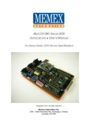
BASE0 <strong>board</strong>On example of a <strong>Fanuc</strong> 15TTA Master<strong>board</strong>5
Install the New BASE0 BoardMake sure that there is a current backup of NC Parameters, Pitch Error Compensation,Offsets, PMC Parameters and Part Programs as explained in “Backup All Parameters”,starting on page 2. The following steps will delete all data from your control.Replace BASE0 Board1. With the <strong>Fanuc</strong> control powered off and the Emergency Stop button depressed, accessthe control’s Master<strong>board</strong>. Find Slot 01PE (connector CAN) just left of centre. Labelall cables and their connection locations to ensure correct reconnection.2. Using a long Philips screwdriver on the retaining screw, carefully remove the BASE0<strong>board</strong> and place it in the anti-static bag provided. Install the new BASE0 <strong>board</strong> in thesame slot and fasten the retaining screw.3. Reconnect all cables to the new <strong>board</strong> exactly as they were connected to the old<strong>board</strong>.Clear MemoryWith the 7 & 9 keys depressed, power on the control, and keep the 7 & 9 keysdepressed until you see the message “CLEAR FILE: RAM TEST”. This will clear theentire memory. If the control will not power on at this point, check that main power isrestored and the cabinet door interlock is bypassed. The control may take a few secondsto clear the entire memory. When it finishes, Press 6 and INPUT to exit IPL mode.Ignore the alarms and turn the control power off and back on.The new memory has now been initialized and all parameters must now berestored.6
Restore The ControlRestore From Computer1. The communications settings must be manually restored from the chart onpage 17. Set Parameter Write Enable, #8000, to “1100 0111”. Select the SETTINGS screen and enter the settings from page 17.Restore NC Parameters2. Get the computer ready to send the NC data. Make sure its serialcommunications settings match the CNC’s corresponding settings. Select EDIT mode, and press the Emergency Stop button. Press softkeys < SERVICE CHAPTER PARAMETER> READ PARAMETER Send the data from the computer. When it finishes, power the control OFF and back ON.Restore PMC Data3. Get the computer ready to send the PMC data. Make sure the CNC is readyto receive the PMC data. Press the Emergency Stop button. Set #8000 to “1111 1111”. Press the CNC/PMC key to display the PMC screen. Press PCPRM , KEEPRL and set #K17.7 to 1 (“1xxx xxxx”) Press < , SYSPRM and set PG CHANNEL to port 1 or 2. Press softkeys < EDIT PASWRD ENAON < < I/O FDCASINPUT EXEC Send the PMC backup from the computer. When it finishes, power the control OFF and back ON.7
Restore Offsets4. Get the computer ready to send the Offsets data. Confirm EDIT mode is selected. Press < PROGRAM CHAPTER > > READ O1 EXEC Send the Offsets backup file from the computer. Switch to PROGRAM screen and select “O0001” on screen Switch to MEMORY mode. Press the CYCLE START button. Once the program is finished executing, delete it.Restore Macro Variables5. Get the computer ready to send the Macro Variable data. Confirm EDIT mode is selected. Press < PROGRAM CHAPTER > > READ O1 EXEC Send the Macro backup file from the computer. Switch to PROGRAM screen and make sure O1 is selected Switch to MEMORY mode. Press the CYCLE START button. Once the program is finished executing, delete it.Restore Part Programs6. Set parameter 0011.0 and 2201.0 to 0 to unprotect part programs in the8000 and 9000 series. Confirm EDIT mode is selected. Press < PROGRAM CHAPTER > > READ ALL EXEC Send the part programs from the computer. Set parameter 0011.0 and 2201.0 to 1 to protect part programs in the8000 and 9000 series from editing.Check that the any FAPT or CAP parameters (if they exist) are also complete –if not, reload.8
Verify The ControlOnce the upgrade is completed, including the reloading of all parameters, testthe machine via the following procedure.IMPORTANT: Do not move the machine until you are sure all parametershave been restored. Change to either MDI mode or Program mode. Home all axes, tool changers and pallets. Check spindle functionality through all speeds and gear ranges. Check Clockwise and Counter-clockwise spindle rotation with M3 and M4commands. Check the tool changer. Be sure that the tool received was the toolrequested and that the carousel rotates in the proper direction. Check the pallet changer (if applicable). If the machine requires specialcustom macros <strong>for</strong> a pallet changer or tool changer, be sure that they arepresent.Note:If you have absolute encoders, they will need to be reset or else youwill Overtravel alarms when you first move the axes.Power on holding “P” and “Cancel” and then manually home themachine to reset these. Also the IPL screen may have an Overtravelreset.Look also at parameter 1815.9
Installation Checklist Check machine - Power ON and check <strong>for</strong> problems be<strong>for</strong>e starting. Backup settings, parameters and programs. Power OFF. Depress E-STOP. Change BASE0 <strong>board</strong>s. Power On the Control with 7 & 9 to clear all. Set PWE to enable. Restore settings. Restore parameters & part programs. Check the parameters and machine operation thoroughly.You Are Complete...10
<strong>Fanuc</strong> <strong>15A</strong> Technical SummaryPunchingNC Parameters EDIT mode; softkeys SERVICECHAPTER PARAMETER > PUNCH ALLPC ParametersAll ProgramsOffsets11EDIT mode; DGNOS screen;OUTPUT/STARTEDIT mode; < PROGRAM CHAPTER> > PUNCH ALL EXECEDIT mode; softkeys < OFFSETCHAPTER PUNCH ALL EXECReadingNC Parameters EDIT mode; softkeys SERVICECHAPTER PARAMETER > READ ALLPC ParametersAll ProgramsEDIT mode; DGNOS screen; INPUTEDIT mode; < PROGRAM CHAPTER> > READ ALL EXECOffsetsEDIT mode; < PROGRAM CHAPTER> > READ ALL EXECMEMORY mode; CYCLE STARTInitializingErase Entire Memory Power On holding 7 & 9with Write Protect Key offTypical Serial Communications Parameter SettingsParameter Description Setting0 Various communications settings See manual8.0-3 Baud rate of Device No. 1 1010=9600, 1001=48008.4 Stop Bits of Device 1 0 = 1 bit (1 = 2 bits)8.5 DC Codes used <strong>for</strong> Device 1 0 = Used8.7 Feed characters <strong>for</strong> Device 1 1 = Not output9 Same as 8 but <strong>for</strong> Device 220 & 22 Fore-& Background Input channel 0 or 1 = Connector JD5A21 & 23 Fore-& Background Output channel 1 = Connector JD5A5001 Device Number of Channel 1 1 = use settings in 5110-51125002 Device Number of Channel 2 2 = use settings in 5120-51225110 Device type of Device No. 1 3 = Xon/Xoff, no feed char.5111 No. of Stop Bits of Device No. 1 1 or 2 = No. of Stop Bits5112 Baud rate of Device No. 1 9 =2400,10 =4800, 11 =96005120 – 5122 = same as 5110 – 5112 but <strong>for</strong> Device No. 2
Applicable BASE0 BoardsBASE0 Board No. <strong>Fanuc</strong> Model Applicable toA16B-2200-0120 15-MA, 15-TA, 15-TTAA16B-2200-0121 15-MF, 15-TF, 15-TTFA16B-2200-0124 15-M, 15-TFA16B-2200-0127 15-MFA16B-2200-0129 15-TF, 15-TTFStandard <strong>Fanuc</strong> Serial Port: (db25 Female)1 = Frame Ground 6 = Data Set Ready2 = Transmit Data 7 = Signal Ground3 = Receive Data 8 = Carrier Detect4 = Ready To Send 20 = Data Terminal Ready5 = Clear To Send 25 = +24 Volts DCStandard <strong>Fanuc</strong> Serial CableComputer<strong>Fanuc</strong>25-pin Female 25-pin MaletoTx – 2 - 3 – RxRx – 3 - 2 – TxRTS – 4 - 5 – CTSCTS – 5 - 4 – RTSSG – 7 - 7 – SG6-8-20 jumperedFG – 1 - No Connection9-pin Female 25-pin MaletoTx – 3 - 3 – RxRx – 2 - 2 – TxRTS – 7 - 5 – CTSCTS – 8 - 4 – RTSSG – 5 - 7 – SG6-8-20 jumperedFG – (D-shell) No Connection-<strong>Fanuc</strong> Protocol: E,7,xThe standard serial communications protocol <strong>for</strong> <strong>Fanuc</strong> controls is always Even Parity and 7 Data Bits.Stop Bits are either 1 or 2, as set via parameter 5111 or 5120 (see “Typical Serial CommunicationsParameter Settings” on page 13).12
<strong>Memex</strong> Technical Support & ServiceIn case of technical difficulty with the memory upgrade procedure, please contact your<strong>Memex</strong> dealer, or call <strong>Memex</strong> <strong>Automation</strong> Technical Support at 1-905-635-3041. Page16 of this manual may be used to record technical in<strong>for</strong>mation, service advice, etc. asneeded.If you have any other questions or concerns, need answers to technical questions, or needin<strong>for</strong>mation about <strong>Memex</strong> products and/or services, please contact your local <strong>Memex</strong>dealer, or contact us at:<strong>Memex</strong> <strong>Automation</strong> Inc200 – 3425 Harvester Rd.,Burlington, Ontario Canada L7N 3N1Phone: 1-905-635-1540 Fax: 1-905-631-9640www.memex.caEmail:support@memex.ca13
Notes14
Serial Communications ParametersPar.# Value0202150002223Par.# Value Par.# Value Par.# Value Par.# Value Par.# Value5001500250705071A507350745081508250835084511051115112512051215122Appendix A: Parameter RecordsBinary HexNote: Grey boxes are <strong>for</strong> Remote Buffer Unit (RBU <strong>board</strong>, labelled "OP1").11.0 2201.0Binary HexBinary HexBinary HexCompany:________________________________ Machine No.:________________ Date:_________________<strong>Fanuc</strong> System <strong>15A</strong> Machine Parameter Worksheet<strong>Fanuc</strong> Software Version: _______________ Main CPU Board No.:___________________________________Setting (Handy) ScreenInput Device (BackGround)TV CheckPunch CodeInput UnitInput DeviceOutput DeviceBinary to Hexadecimal Conversion0 0 0 00 0 0 10 0 1 00 0 1 101230 1 0 00 1 0 10 1 1 00 1 1 14567Output Device (BackGround)Mirror Image XMirror Image YMirror Image Z1 0 0 01 0 0 11 0 1 01 0 1 189AB1 1 0 01 1 0 11 1 1 01 1 1 1CDEFExample: 110101011 1 0 1 =0 1 0 1 =1101 0101 =D5D515
9110 OP119120 OP21Option ParametersPar.#91009101910291039104910591069107910891099110911191129113911491159116911791189119Binary Hex OP# Par.#9120OP1OP2OP3OP4OP5OP6OP7OP8OP9OP10OP11OP12OP13OP14OP15OP16OP17OP18OP19OP20- Original- Updated91219122912391249125912691279128912991309131913291339134913491359136913791389139Binary Hex OP# Par.#OP21OP22OP23OP24OP25OP26OP27OP28OP29OP30OP31OP32OP33OP34OP35OP35OP36OP37OP38OP39OP40- Original- Updated- Original- Updated91409141914291439144914591469147914892009201920292039204920592069207920892099210Binary Hex OP#NOTE: A newer machine may have more 9100 series parameters - it is imperative to record them all.OP41OP42OP43OP44OP45OP46OP47OP48OP49OP50OP51OP52OP53OP54OP55OP56OP57OP58OP59OP6016
Timers Spare Counters Keep RelaysData Data Data No. DataPC ParametersNo. No. No. No.1234567891011121314151617181920212223242526272829303132333435363738394012345678910111213141516171819201234567891011121314151617181920Preset Current12345678910111213141516171817
Data TablesNo.0"No. of Data" row 0 indicates how many data tables there are. The remaining rows inthat column indicate how many entries are in each table. Page down through eachtable and record all the data in each, using the <strong>for</strong>m on the next two pages -photocopy the <strong>for</strong>m be<strong>for</strong>e starting, if more are needed.1234567891011121314Parameter No. of DataOffset Special Table No. 018
19123456789No.0Data012345678901234123456789No.0Data012345678901234123456789No.0Data012345678901234123456789No.0Data012345678901234
2056789012345678901234567890567890123456789012345678905678901234567890123456789056789012345678901234567890
<strong>Memex</strong> <strong>Automation</strong> Inc.200 – 3425 Harvester Rd.,Burlington, OntarioCanada L7N 3N1Phone: 905-635-1540 Fax: 905-631-9640www.memex.caSupport: (905) 635-3041Sales: (905) 635-3043Thank you <strong>for</strong> using <strong>Memex</strong> products\ISO9000\DOCs\Current <strong>Manual</strong>s\M100718C – MAI Memory Upgrade <strong>for</strong> <strong>Fanuc</strong> <strong>15A</strong>.doc21