Mx1100 Serial BTR for Fanuc Manual - Memex Automation
Mx1100 Serial BTR for Fanuc Manual - Memex Automation
Mx1100 Serial BTR for Fanuc Manual - Memex Automation
- No tags were found...

Create successful ePaper yourself
Turn your PDF publications into a flip-book with our unique Google optimized e-Paper software.
<strong>Mx1100</strong> UMI <strong>Serial</strong> <strong>BTR</strong>Installation & User’s <strong>Manual</strong>For <strong>Fanuc</strong> Tape ReadersCopyright © 2013 All rights reserved.<strong>Memex</strong> <strong>Automation</strong> Inc.200 – 3425 Harvester Rd.,Burlington, OntarioCanada L7N 3N1
<strong>Mx1100</strong> UMI <strong>Serial</strong> <strong>Fanuc</strong> <strong>BTR</strong>
Table of ContentsIntroduction............................................................................VIIAbout This <strong>Manual</strong>............................................................VIIHistory of the <strong>BTR</strong>............................................................VIIInstallation Instructions......................................................... 1Package Contents........................................................…...1Installing the <strong>Mx1100</strong> UMI <strong>BTR</strong>...................................... 2Operating The <strong>BTR</strong>........................................................... 5Layout Diagram of the <strong>Mx1100</strong> UMI <strong>Serial</strong> <strong>BTR</strong>............ 6Reference................................................................................. 7General Troubleshooting................................................... 7<strong>Memex</strong> Technical Support & Service............................. 11User’s Notes.................................................................... 12Glossary................................................................................. 13Appendix A: Configuration & Settings………………….. 17DNC Software Configuration In<strong>for</strong>mation...................... 17<strong>Mx1100</strong> Option Jumper Settings..................................... 17<strong>Mx1100</strong> <strong>Serial</strong> Port Pin Configuration............................ 18<strong>Serial</strong> Data Cable Configurations.................................... 18Appendix B: ASCII Code Reference Table........................ 19Contents _III
Contents _IV
5. Mount the <strong>BTR</strong>.Locate a safe spot on the back of the door and magneticallymount the <strong>Mx1100</strong> UMI <strong>BTR</strong>.6. Option: Connect the Tape Reader to the <strong>BTR</strong>.If you wish to enable the paper Tape Reader, take the new 50-conductor ribbon cable and plug it onto the JP5 connector(labelled “FANUC TAPE READER A”) at the bottom right ofthe <strong>BTR</strong>.* The red side of the cable goes on pin 1 of theconnector (see diagram, page 6). Plug the other end of the cableonto the CNT1 connector on the <strong>Fanuc</strong> Tape Reader board, fromwhich the cable was removed in Step 3 – ensuring the red wire onthe ribbon cable goes on pin 1 of the connector, as noted in Step3.7. Option: Punch Cable.If you would like to punch part programs, parameters, etc. fromthe control to the computer, and you have purchased the optional<strong>Fanuc</strong> Facit 4070 Punch Cable, connect the control’s punch portto the <strong>BTR</strong>. Locate the punch port on the control. It’s usually ablue rectangular 20-pin (Honda) connector. Plug the Punch Cableinto this port. Plug the 26-pin end onto the <strong>BTR</strong>’s JP4 connector,labelled “PUNCH IN”. The red stripe goes on the side with Pin 1(see diagram on page 6). Remove the JP17 jumper (labelled“PUNCH DISABLE”) in the upper right corner of the <strong>BTR</strong>.8. Configure the <strong>BTR</strong>.Set the jumpers on the <strong>BTR</strong> to configure the communicationsparameters required <strong>for</strong> your DNC system. The option jumpers,listed on page 17, include the following:Note:Jumper A1 and A2 set the Baud rate. Typically 9600 baud(both jumpers ON) is used unless your cable doesn’t supportthat rate reliably. The RS232 specification supports 9600Baud (Even parity, 7 data bits and 1 stop bit) with a cablelength up to 50 feet (15 metres), but it is often possible toexceed that. It’s important to use cable specifically designed<strong>for</strong> RS232 serial data, 22 AWG, twisted pair, stranded wire(not solid), shielded, low capacitance (a rating of 11 to 15 pFper foot) is best. If you have a long cable run or are haveunreliable data transmission, try lowering the Baud rate.In our opinion, CAT3 or CAT5 UTP Ethernet cable is not suitable <strong>for</strong>reliable machine tool serial communications. Use shielded cable.Chapter 1: Installation Instructions _ 3
Jumper A3 OFF adds hardware (RTS/CTS) handshaking.A3 ON is software (Xon/Xoff) only. Generally it is preferableto use both, which means setting A3 OFF and making sureyour cable supports hardware handshaking (see Note 6 on p 9).Jumper A4 OFF uses the standard Xoff character, $13 Hex.Set A4 ON if your terminal software uses $93 Hex <strong>for</strong> Xoff.Jumper A5 OFF uses the standard Xon/Xoff handshakingmethod (a Single Xoff). Setting A5 ON sends a continuousstream of Xoff back to the computer until the next Xon. Thisenables the <strong>BTR</strong> to be used with some terminal programs thatwere intended <strong>for</strong> use with a modem, such as PROCOMM although we recommend the use of proper DNC software.Jumper A6 OFF will echo incoming data back to the PC <strong>for</strong>diagnostic purposes. On reset, the software version isoutputted <strong>for</strong> instance. Set A6 ON <strong>for</strong> normal use.Jumper A7 OFF is ISO data, and ON converts incoming ISOdata to EIA <strong>for</strong>mat <strong>for</strong> controls that require EIA data.Jumper A8 overrides the Tape Reader’s selection of <strong>BTR</strong> orTape mode. If the Tape Reader wasn’t reconnected to the<strong>BTR</strong>, or if the Tape Reader isn’t intended to be used often andthe <strong>BTR</strong> will usually in Tape mode, set A8 ON. (Remember toremove it when a tape needs to be read.)__________________________________________________SG JMPR OFF = COM1 Signal Ground surge suppression.PWR P9 DBL ON activates power output on COM1’s pin 9,<strong>for</strong> use with devices such as buffers (see note on page 18).Punch Disable – if you are not using a Facit 4070 punch port(SKU-5100 cable), keep this jumper ON.9. Connect to the Computer.Connect a serial cable from the 9-pin COM1 on the <strong>BTR</strong> to thecomputer’s serial port (see page 18 <strong>for</strong> cable configurations).10. Test the Functionality.Refer to “Operating the <strong>Mx1100</strong> UMI <strong>BTR</strong>” (page 5), and ifnecessary, “Reference” (page 7).Chapter 2: Operating the <strong>Mx1100</strong> _ 4
Operating the <strong>Mx1100</strong> UMI <strong>BTR</strong>To use the control’s new serial port:Make sure the cables are connected correctly and prepare your DNCsoftware. Press Reset on the <strong>Fanuc</strong> control to reset the <strong>BTR</strong> and ensurethat no residual data is present in its input buffer. If <strong>BTR</strong> option jumperA8 is OFF (switch enabled), and the Tape Reader is connected, switchthe <strong>BTR</strong> into <strong>BTR</strong> mode either by turning off the Tape Reader or byswitching the Tape Reader to Release mode. Start an upload to thecontrol from your DNC software, and then load a program at thecontrol as if from tape. You can put the control in Tape mode and pressREAD or INPUT to load the program into memory (if it will fit), or putthe control in DNC (or External) mode and press Cycle Start to run it inDNC mode – also known as “drip feeding”. (These mode names andkey names will vary according to the control model.)If you have any difficulty or concerns, please refer to “GeneralTroubleshooting” on page 7.Helpful hintsAdding a couple of Carriage Returns to the end of the file willensure that the entire file is transmitted. Some combinations ofDNC software and CNC control sometimes miss the end of afile, so it’s a good idea to provide some harmless extracharacters as a buffer.The <strong>BTR</strong> responds to the Break character by resetting andclearing its buffer. The Break character is ASCII value 3, orHEX 03 (see Appendix B, page 19). If your DNC software canbe configured to send control codes, it’s a good idea to have itsend a Break character at the beginning of every g-codeprogram it sends. This will guarantee that the <strong>BTR</strong> buffer isreset and ready <strong>for</strong> a new program each time, regardless ofwhether the CNC didn’t properly finish reading the previousone. (The Break character will not be passed through to theCNC, and the start of the program following it will wait whilethe <strong>BTR</strong> is resetting.)Chapter 2: Operating the <strong>Mx1100</strong> _ 5
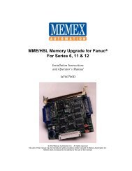
COM 1Connect toComputerResetConfigurationJumpers A1-A8SP1Mode SwitchConnectorJP16, +24TR24 Volt selectorJ7, Power TerminalJP33, PWR P9 DBLEnable power output onCOM1 pin 9JP10, REG ENBL24 Volt regulatorJP4, PUNCH IN26-pin header - Connectto CNC's punch portMEMEX ETHERNET MODULEPowerStatusStatus LEDsPin 1 indicator: Cable's red stripe alwaysgoes on whichever side has this markJP8, FANUC CONTROL A50-pin header - Connect to CNCJP5, FANUC Tape Reader A50-pin header - Connect to TapeReader (Optional)Pin 1 indicator: Cable's red stripe alwaysgoes on whichever side has this mark111JP17Punch DisableCOM1A1A2A3A4A5A6A7A8RESETLOADCable keyway.If cable has no key,be extra carefulorienting the cable+7-24V+5V-GNDJP16+24TRJ7JP22SG JMPRPWR P9 DBLREG ENBLJP10S/N: 030301-MEMEX ELECTRONICS INC.(C)2003PWR ONSTATUSTXRXRTSCTSTXRXRTSCTSCOM1 COM21FANUC CONTROL ACONTROL BJP8JP7TAPE READER BUNIVERSAL MACHINE INTERFACEMX1100 R3MADE IN CANADAWWW.MEMEX.CAFANUC TAPE READER APUNCH DISABLEJP17JP18+5TR111JP18, +5TR5 Volt selectorPUNCH IN JP4TAPE IN JP13SP1 JP3IMPORTANT: If punch cable is connected, JP17 mustIMPORTANT: If +5TR is ON, then bothJP22, SG JMPRDisables SignalGround SurgeSuppression on COM1be OFF; If punch cable is not connected, JP17 must be ON.+24TR and REG ENBL must be OFF;If +5TR is OFF, then both +24TR and REG ENBLmust be ON. (See Note 1 on Page 7.)1JP5JP6Layout of the <strong>Mx1100</strong> UMI <strong>Serial</strong> <strong>BTR</strong>Chapter 2: Operating the <strong>Mx1100</strong> _ 6
ReferenceThis chapter contains troubleshooting hints and in<strong>for</strong>mation about<strong>Memex</strong> Technical Support and Service.General TroubleshootingThe <strong>Mx1100</strong> UMI <strong>BTR</strong> is designed to install easily and quickly.However, if experiencing difficulty in the procedures, please check thefollowing to isolate and resolve the problem:1. Check that the “PWR ON” LED on the <strong>BTR</strong> (leftmost LED inthe LED block at bottom centre*) is on and bright.The RTS LED <strong>for</strong> COM1 should also be on. If there is no power tothe <strong>BTR</strong>, ensure that the cables from the Control (and from theTape Reader if connected) are oriented properly and are wellsecured. Also, check that one of the following is true:a) The “+5TR” jumper (JP18 at bottom right) is ON and the“+24TR” jumper (JP16 at middle left) and “REG ENBL”(JP10 near middle bottom) are OFF; -orb)The “+5TR” jumper (JP18) is OFF and the “+24TR” jumper(JP16) and “REG ENBL” (JP10) are ONIn case “a” above, the <strong>BTR</strong> is sourcing 5 volts from the CNC; incase “b” it is sourcing 24 volts and reducing it to 5 volts.Typically 5V (setting “a”) is used with a <strong>Fanuc</strong> control.NOTE: The default power source setting is “a” above, 5 volts.However, in some CNCs the 5-volt supply has faded to below thethreshold that will power the <strong>BTR</strong>. If the <strong>BTR</strong> won’t power on, tryusing 24 volts by setting the jumpers as in “b” above.2. Alternate source of powerIf the PWR LED still does not come on, carefully find a source ofpower on the control between 7 and 24VDC and wire it in toscrew-down terminal block J7 at the lower left corner of the <strong>BTR</strong>When power is brought in through the terminal block, the jumpersmust be set as in “b” above.Note:Chapter 2: Operating the <strong>Mx1100</strong> _ 7
3. Check that the <strong>BTR</strong> is working properly.When the control is powered up or reset, the <strong>BTR</strong>’s STATUS LED(2 nd LED in LED block at middle bottom) should blink. One blinkindicates that the <strong>Mx1100</strong> is in <strong>BTR</strong> Mode. This means that it isready to receive in<strong>for</strong>mation through the serial port and to send itto the control. Two blinks indicate that the <strong>Mx1100</strong> is in TAPEMode. This means that it is ready to pass in<strong>for</strong>mation through the<strong>BTR</strong> from the Tape Reader to the Control. (The leftmost TX LEDwill also blink, as the <strong>BTR</strong> sends out a status message on itsCOM1 port during power up.) With most Tape Readers, turningthe Tape Reader on/off or switching it between Load and Releasewill switch the <strong>BTR</strong> between modes.4. Check the status message.When the <strong>BTR</strong> is powered on or reset, it sends a short message onits COM1 port, indicating which mode it’s in. The STATUS andfirst TX LEDs will blink during output. If the computer is properlyconnected, and your DNC software is configured to match the<strong>BTR</strong> communication settings and is set to receive a file, it shouldbe possible to capture and read the status message. If the messageis clearly readable then the <strong>BTR</strong>’s communications are good, andso is the cable, the settings, the computer and the DNC software.NOTE: Some versions of the <strong>BTR</strong> require the A6 Jumper to beoff (echo enabled) <strong>for</strong> the status message to be sent back to thePC on Power Up5. The Status and Tx LEDs flash but there is no status message.First the computer has to be watching <strong>for</strong> the status message withDNC software, or at least with a terminal program or utility. Afterinstalling your software, verify that the correct communicationparameters are set and check that the correct computer COM portis being used. Check that the BAUD RATE is properly set andmatches the baud rate on the <strong>BTR</strong> (check option jumpers A1 andA2 – see pg. 17) and that the STOP BITS are set to 1. Make surethat the cable connecting the <strong>BTR</strong> to the computer is a properlyconfigured RS-232 serial data cable and that it is properlyconnected (see Step 6 below). Also verify that the PC’s COM portis functioning properly.Chapter 2: Operating the <strong>Mx1100</strong> _ 8
6. Check the serial data cable and handshaking settings.First, make sure the cable matches the appropriate diagram under“<strong>Mx1100</strong> UMI <strong>BTR</strong> Cable Configurations” (page 18).Second, make sure the cable, <strong>BTR</strong> settings and software settingsmatch with regard to handshaking method. If using softwarehandshaking (Xon/Xoff) only (see table A on page 18), make surethat <strong>BTR</strong> Jumper A3 is ON and your DNC software is set <strong>for</strong>Xon/Xoff handshaking only. If using hardware handshaking (seetable B on page 18), make sure that <strong>BTR</strong> Jumper A3 is OFF, yourDNC software is set <strong>for</strong> RTS/CTS and Xon/Xoff handshaking, andthe cable supports it by having the wires <strong>for</strong> RTS and CTSconnected <strong>for</strong> a total of five wires connected at each end. (Note:Software handshaking can be used with a hardware handshakingcable, but not the other way around.)Third, make sure every wire connection at each end of the cable issolid, there are no breaks in the wires, no wire insulation is pulledback far enough to allow bare wire to touch another wire or anyother metal parts, and no solder or debris is touching more thanone pin. If everything looks good at the ends, it may be necessaryto use a multi-meter to determine whether there is a break or ashort in the wires somewhere along the length of the cable.If a hardware handshaking cable is being used, the leftmost CTSLED (in the STATUS LED bank at bottom centre of the <strong>BTR</strong>) willlight up when a properly configured cable is connected betweenthe <strong>BTR</strong> and a computer and both are powered on. The leftmostRTS LED will always be on, indicating that the <strong>BTR</strong> is active andthe port is ready. Regardless of which type of handshaking is beingused, the leftmost RX LED will blink when data is sent to the<strong>BTR</strong>, and the leftmost TX LED will blink during any Xon/Xoffhandshaking that might occur during the send.7. The whole file sends be<strong>for</strong>e pressing Cycle Start.The most common cause of this is incorrect handshaking settings.Refer to Note 6 above. In addition, some terminal programs expectthe XOFF character, normally Hex 13, to include even parity,making it Hex 93. Try setting jumper A4 ON (see page 17).Chapter 2: Operating the <strong>Mx1100</strong> _ 9
8. A CNC error occurs shortly after pressing “Cycle Start”.Try removing the CR (carriage return) characters from theprogram. Some controls only accept “pure” ISO or EIA code,which does not contain CR characters. Also try changing <strong>BTR</strong>jumper A7 in case it’s a matter of ISO / EIA <strong>for</strong>mat mismatch.9. The control generates a Tape Vertical (TV) alarm.Tape Vertical checking was a way that controls verified theaccuracy of the program code they read in through the TapeReader. It is usually an option and does not apply when you areusing a <strong>BTR</strong>. Turn this option off in the control’s parameters.10. The control generates a Tape Horizontal (TH) alarm.Tape Horizontal is equivalent to Even parity. Use Even paritywhen sending the programs from the terminal or PC. Also seeNotes 7 and 8 above – jumper A4 and/or A7 may resolve this.11. The Power LED lights but the STATUS LED doesn’t flash.Check the supply voltage to the <strong>BTR</strong>. If using a 5VDC supply andit is less than 4.6VDC, the <strong>BTR</strong> may actually be protecting itselffrom under-voltage. Find a better 5V supply, or switch to 24V (seeNote 1 “b”) or use the screw-down terminal in the bottom leftcorner with a supply of 7 to 24VDC. Always be sure to set up thepower jumpers correctly (see Notes 1 and 2).12. Other machine errorsEnsure that the proper tape codes are being used at the beginningand/or end of the program. Some machines require a “%” (percentsign) as the first and/or last character in the program. Check theCNC Operator’s <strong>Manual</strong> <strong>for</strong> any termination characters that maybe required.13. What if the <strong>BTR</strong> “Locks Up”?Near the upper left corner of the <strong>BTR</strong> are the four pins labelledRESET and LOAD. Of those four pins, the top two are the resetpins. Momentarily shorting the two RESET pins by touching themwith a metal object such as a screwdriver or coin (while the poweris on) will reset the <strong>BTR</strong> and make the STATUS LED flash. Thisaction is the equivalent of pressing the reset button on a PC. Thisshould not have to be done on a regular basis, but, as with anythingelectronic, lockup can happen.Chapter 2: Operating the <strong>Mx1100</strong> _ 10
<strong>Memex</strong> Technical Support & ServiceIn case of technical difficulty with the <strong>Mx1100</strong> UMI <strong>BTR</strong>, be sure toreview the troubleshooting section of this manual prior to calling <strong>for</strong>technical support. If the issue cannot be resolved after reading throughthe troubleshooting section, please contact <strong>Memex</strong> <strong>Automation</strong>Technical Support at 1-905-635-3042. Page 12 of this manual may beused to record technical in<strong>for</strong>mation, service advice, etc. as needed.If you have any other questions or concerns, need answers to technicalquestions, or need in<strong>for</strong>mation about <strong>Memex</strong> products and/or services,please contact your local <strong>Memex</strong> dealer or us at:<strong>Memex</strong> <strong>Automation</strong> Inc.200 – 3425 Harvester Rd.,Burlington, OntarioCanada L7N 3N1Phone: 905-635-1540Fax: 905-631-9640Web: www.memex.caEmail: sales@memex.casupport@memex.caChapter 2: Operating the <strong>Mx1100</strong> _ 11
Notes:Chapter 2: Operating the <strong>Mx1100</strong> _ 12
Glossary:ANSI American National Standards Institute. The official USagency and voting representative <strong>for</strong> ISO. This institute developsin<strong>for</strong>mation exchange standards above 50 Mbps.ASCII American Standard Code <strong>for</strong> In<strong>for</strong>mational Interchange. Aseven bit alphanumeric code used extensively in data communications.A parity bit is often added to the seven-bit code <strong>for</strong> error detection.See Appendix B, page 19 <strong>for</strong> a table of ACSII values.ASYNCHRONOUS TRANSMISSION The transmission ofcharacters separated by time intervals that vary in length, usually inaccordance with the key entries of a terminal operator. Start and stopbits are used to identify (frame) the beginning and end of theasynchronously transmitted character.BAUD RATE The rate at which a signal is changed or modulated.Refers to the number of bits transmitted per second.<strong>BTR</strong> Behind the Tape Reader. An electronic input device thatemulates a Tape Reader’s signals on a machine control, usuallyconverting serial communications to parallel Tape Reader signals.CNC Computerized Numerical Control. An industrial computer thatis used to control the movement of a machine. A CNC usually usesprograms coded with G-codes and M-codes.CONTROL Refers to a Computerized Numerical Control (CNC).CTS Clear To Send. One of the control lines used in RS232communication. Found on pin 4 or 5 on a DB25 and pin 7 or 8 on aDB9 depending whether the port is DTE or DCE.DCE Data Communication Equipment. Typically a modem or dataset used to interface a terminal or computer to the telephone lines.Glossary Glossary _ 13 _ 13
DNC Direct/Distributed Numeric Control. A means ofcommunicating or “drip feeding” a program to a CNC through a TapeReader or serial interface. The program code is immediately executed,block by block, as it is read by the control.DTE Data Terminal Equipment. In data communications, it is anend user or termination circuit, typically a terminal or computer.ECHO A reflected signal. In<strong>for</strong>mation is sent back to the transmitterfrom the receiver, often <strong>for</strong> verification purposes.EIA Electronic Industries Alliance. A United States organization ofmanufacturers that establishes and recommends industrial standards.They developed the EIA standard code used in early NC and CNCcommunications. Also refers to a <strong>for</strong>m of 7 bit ASCII with dataencryption and Odd parity, used largely on CNCs.FRAMING The procedure used to identify the beginning and end of agroup of data bits.FRAMING ERROR An error that occurs when a receiver losessynchronism to the incoming data.G CODE The instructions used to dictate the movement of a machine.A list of these codes is commonly called a “part program”.HANDSHAKING A process that regulates the flow of data betweentwo devices. Also called “flow control”.HARDWARE HANDSHAKING Handshaking (flow control) by useof the RTS and CTS control lines on an RS232 serial interface.ISO International Standards Organization. One of the world’slargest standards organizations. Also refers to a <strong>for</strong>m of 7 bit ASCIIwith data encryption and Even parity, used largely on CNCs.LOCAL ECHO Refers to when a terminal is configured to internallyroute its transmitted character around to its receiver section <strong>for</strong> display.Glossary _ 14
MODEM A contraction of modulator/demodulator. The modemconverts a computer’s digital bit stream into an analog signal suitable<strong>for</strong> telephone lines and vice versa.PAPER TAPE A media of part program storage. Holes were punchedin a one-inch paper tape to represent G codes. These tapes were thenread through a Tape Reader to be loaded into machine control memory.PARITY An error detection method whereby a single bit is added to agroup of bits to make the total number of 1 bits either even or odd(depending on the type of parity; even or odd).PART PROGRAM A list of G codes that control the movement ofthe machine. May be typed into the machine control or produced as acomputer text file and transmitted to the control.PARITY ERROR Indicates that the total number of 1 bits in areceived character does not agree with the type of parity expected.RS232-C An asynchronous serial interface standard that specifies anelectrical, functional, and mechanical interface specification betweendata communication devices.RTS Request To Send. One of the control lines used in RS232communication. Found on pin 4 or 5 on a DB25 and pin 7 or 8 on aDB9 connector depending on whether the port is DCE or DTE.RTS/CTS Hardware handshaking (flow control) using the RTS andCTS control lines.Rx Receive Data. Refers to the input <strong>for</strong> the data signal.SG Signal Ground. Refers to the ground <strong>for</strong> the data signal. Not thesame as the cable’s shield ground or a device’s frame ground.START BIT The first bit used to frame an asynchronouslytransmitted character. Its logic level is a 0 (space).Glossary _ 15
STOP BIT The last bit used to frame an asynchronously transmittedcharacter. Its logic level is a 1 (mark).SYNCHRONOUS TRANSMISSION High-speed communicationwhereby data characters are sent in direct succession to each otherwithout the use of Start and Stop bits.TAPE READER An input device used on CNC Machines and otherindustrial equipment. Used to read coded data on a punched tape. OlderTape Readers were a mechanical device, whereas newer ones useoptical devices that sense light passing through the holes in the tape.TERMINAL An input/output device used by an operator tocommunicate with a host computer. It consists of a keyboard and adisplay to monitor alphanumeric characters entered at the keyboard orreceived from a remote device.TERMINAL SOFTWARE Computer software that enables acomputer to act as a terminal, usually used with modems. Can be usedto exchange data over a serial cable between two computers or acomputer and a machine control, but does not provide the level of flowcontrol necessary to prevent dangerous miscommunications with amachine control. Specific purpose DNC software is highly preferable.TIME-OUT ERROR An error that occurs when a device fails torespond to a message within an expected period of time.Tx Transmit Data. Refers to the output <strong>for</strong> the data signal.XOFF Transmit Off. A device control character (DC3 or $13 hex)used to control the flow of data between two devices. XOFF is usedtogether with XON as a handshake.XON Transmit On. A device control character (DC1 or $11 hex)used to control the flow of data between two devices. XON is usedtogether with XOFF as a handshake.XON/XOFF Software handshaking using the XON and XOFF controlcharacters.Glossary _ 16
Appendix A: Configuration & Settings<strong>Mx1100</strong> UMI <strong>BTR</strong> <strong>Serial</strong> ConfigurationBaud Rate...................... 9600 (default; set by jumpers A1 & A2)Parity............................. EvenData Bits........................ 7Stop Bits......................... 1Handshake...................... See note 6, page 9If using terminal software, these settings may also apply:Duplex............................. FULLASCII transfer options…. Strip the High Bit = ONOption Jumpers on the <strong>Mx1100</strong> UMI <strong>Serial</strong> <strong>BTR</strong>A1= 1200 = 2400 = 4800 = 9600 *A2 Baud Baud Baud BaudA3 Add CTS/RTS flow control Xon/Xoff flow control *A4 Xoff = $13 hex Xoff = $93 hexA5 Single Xoff Continuous (strobed) XoffA6 Echo No Echo *A7 No conversion ISO – EIA conversionA8 <strong>BTR</strong> Mode controlled by Force <strong>BTR</strong> modeTape Reader Switch+24TR JP16 Enable 24V power from Tape Reader+5TR JP18 Enable 5V power from Tape ReaderREG ENBL JP10 Enable 5V Power RegulatorPunch Disable JP17 * Use if Punch Port not connectedSG JMPR JP22 Disable COM1 signal ground surge suppressionPWR P9 DBL JP23 Enable power output on COM1 pin 9 *** Default Settings (9600, E71, XON/XOFF, no Echo, no punch)NOTE:= NO Jumper = Jumper ONAppendix A: Configuration & Settings _ 17
Appendix A: Configuration & Settings _ 20
<strong>Memex</strong> <strong>Automation</strong> Inc.200 – 3425 Harvester Rd.,Burlington, OntarioCanada L7N 3N1Phone: 905-635-1540 Fax: 905-631-9640www.memex.caSupport – (905) 635-3042support@memex.caSales – (905) 635-3041sales@memex.caThank you <strong>for</strong> choosing <strong>Memex</strong> <strong>for</strong> yourManufacturing Connectivity Solutions\ISO9000\DOCs\Current <strong>Manual</strong>s\M100707D - <strong>Mx1100</strong> <strong>Serial</strong> <strong>BTR</strong> <strong>for</strong> <strong>Fanuc</strong>.doc