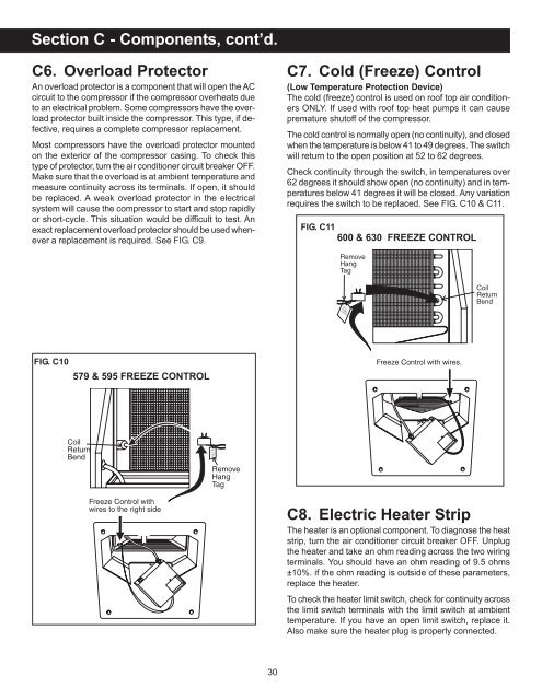
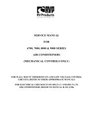
Section C - Components, cont’d.C6. Overload ProtectorAn overload protector is a component that will open the ACcircuit to the compressor if the compressor overheats dueto an electrical problem. Some compressors have the overloadprotector built inside the compressor. This type, if defective,requires a complete compressor replacement.Most compressors have the overload protector mountedon the exterior of the compressor casing. To check thistype of protector, turn the air conditioner circuit breaker OFF.Make sure that the overload is at ambient temperature andmeasure continuity across its terminals. If open, it shouldbe replaced. A weak overload protector in the electricalsystem will cause the compressor to start and stop rapidlyor short-cycle. This situation would be difficult to test. Anexact replacement overload protector should be used whenevera replacement is required. See FIG. C9.C7. Cold (Freeze) Control(Low Temperature Protection Device)The cold (freeze) control is used on roof top air conditionersONLY. If used with roof top heat pumps it can causepremature shutoff of the compressor.The cold control is normally open (no continuity), and closedwhen the temperature is below 41 to 49 degrees. The switchwill return to the open position at 52 to 62 degrees.Check continuity through the switch, in temperatures over62 degrees it should show open (no continuity) and in temperaturesbelow 41 degrees it will be closed. Any variationrequires the switch to be replaced. See FIG. C<strong>10</strong> & C11.FIG. C116<strong>00</strong> & 630 FREEZE CONTROLDokdkdmfmfFIG. C<strong>10</strong>579 & 595 FREEZE CONTROLC8. Electric <strong>Heat</strong>er StripThe heater is an optional component. To diagnose the heatstrip, turn the air conditioner circuit breaker OFF. Unplugthe heater and take an ohm reading across the two wiringterminals. You should have an ohm reading of 9.5 ohms±<strong>10</strong>%. if the ohm reading is outside of these parameters,replace the heater.To check the heater limit switch, check for continuity acrossthe limit switch terminals with the limit switch at ambienttemperature. If you have an open limit switch, replace it.Also make sure the heater plug is properly connected.30
Section C - Components, cont’d.C9. Selector SwitchC9a. Selector Switch - Roof Top <strong>Air</strong><strong>Conditioner</strong>The selector switch in a mechanical air conditioner hasseveral positions. The various switch positions can be testedfor continuity with a volt/ohm meter set on the highest ohmscale. See FIG. C12.First turn the 20 amp air conditioner breaker to OFF andremove wires from the switch.With the switch in the OFF position, you should not havecontinuity between terminal L1 and any other terminals.In the HIGH FAN position, you should have continuity betweenL1 and terminal 1.In the MEDIUM FAN position, you should have continuitybetween L1 and terminal 2.In the LOW FAN position, you should have continuity betweenL1 and terminal 4.In the HIGH COOLING mode, you should have continuitybetween L1 and C, and L1 and 1.In the MEDIUM COOLING mode, you should have continuitybetween L1 and C, and L1 and 2.In the LOW COOLING mode, you should have continuitybetween L1 and C, and L1 and 4.In the HEATING mode, you should have continuity betweenL1 and H, and L1 and 4.Be sure to check the switch in all positions and be sure youhave continuity only on the terminals for the selected mode.Lack of continuity or continuity on incorrect terminals designatesa defective switch, and it must be replaced.FIG. C12Position TerminalsOFFHI FAN L1 and 1MED FAN L1 and 2LOW FAN L1 and 4HI COOL L1 and C; L1 and 1MED COOL L1 and C; L1 and 2LOW COOL L1 and C; L1 and 4HEAT L1 and H; L1 and 4C9b. Selector Switch - Roof Top <strong>Heat</strong><strong>Pump</strong>The selector switch in a mechanical heat pump has severalpositions. The various switch positions can be testedfor continuity with a volt/ohm meter set on the highest scale.See FIG. C13.Model 59126.501 First turn the 20 amp heat pump breakerto OFF. Next, remove the wires from the switch. With theswitch in the OFF position, you should not have continuitybetween Terminal L1 and any other white numbered terminal.In the HIGH 2 FAN position, you should have continuitybetween Terminal L1 and Terminal 4 only.In the HIGH 1 FAN position, you should have continuitybetween Terminal L1 and Terminal 2 only.In the LOW FAN position, you should have continuitybetween Terminal L1 and Terminal 1 only.In the LOW COOLING position, you should have continuitybetween Terminal L1 and Terminal C; and TerminalL1 and Terminal 1 only.In the HIGH 1 COOLING position, you should havecontinuity between Terminal L1 and Terminal C; andTerminal L1 and Terminal 2 only.In the HIGH 2 COOLING position, you should havecontinuity between Terminal L1 and Terminal C; andTerminal L1 and Terminal 4 only.In the HEAT PUMP position, you should have continuitybetween Terminal L1 and Terminal H; and TerminalL1 and Terminal 4 only.Note: The terminals are identified with white ink.Be sure to check the switch in all positions and be sure youhave continuity only on the terminals for the selected position.Lack of continuity or continuity on incorrect terminalsdesignates a defective switch, and it must be replaced.Note: The numbers without circles are the white inkstampednumbers.FIG. C13Position TerminalsOFFHIGH 2 FAN L1 and 4HIGH 1 FAN L1 and 2LOW FAN L1 and 1LOW COOLING L1 and C; L1 and 1HIGH 1 COOLING L1 and C; L1 and 2HIGH 2 COOLING L1 and C; L1 and 4HEAT PUMP L1 and H; L1 and 431
- Page 1 and 2: AIR CONDITIONER & HEAT PUMPSERVICE
- Page 3: A1. AC VoltageThe unit is a 115VAC,
- Page 6: Section A - Installation, cont’d.
- Page 9 and 10: A6a. Roof Top UnitsSection A - Inst
- Page 11 and 12: A6b. Basement Unitswill have the
- Page 13 and 14: A6b. Basement UnitsFREE AREA - is t
- Page 15 and 16: Section A - Installation, cont’d.
- Page 17 and 18: B1b. Bimetal Relay ControlsCooling
- Page 19 and 20: B1d. Comfort Control CenterON/OFF S
- Page 21 and 22: B1d. Comfort Control CenterHeat Pum
- Page 23 and 24: B1d. Comfort Control CenterFIG. B11
- Page 25 and 26: B2. Heat Pumpleaves the outside coi
- Page 27 and 28: B2. Heat PumpFIG. B18 13Wait at lea
- Page 29 and 30: C1. MotorsRoof Top Units - To check
- Page 31: Section C - Components, cont’d.Th
- Page 35 and 36: Section C - Components, cont’d.Fo
- Page 37 and 38: Section C - Components, cont’d.C1
- Page 39 and 40: Section C - Components, cont’d.Th
- Page 41 and 42: Section C - Components, cont’d.RC
- Page 43 and 44: Section C - Components, cont’d.FI
- Page 45 and 46: Section C - Components, cont’d.Be
- Page 47 and 48: Section C - Components, cont’d.FI
- Page 49 and 50: Section C - Components, cont’d.Mo
- Page 51 and 52: Section C - Components, cont’d.Wi
- Page 53 and 54: Section C - Components, cont’d.Ea
- Page 55 and 56: Section C - Components, cont’d.Tw
- Page 57 and 58: Section C - Components, cont’d.C2
- Page 60 and 61: Section C - Components, cont’d.21
- Page 62 and 63: Section D - ConfigurationDucted Ins
- Page 64 and 65: Section D - Configuration, cont’d
- Page 66 and 67: Section D - Configuration, cont’d
- Page 68 and 69: Section D - Configuration, cont’d
- Page 70 and 71: Section D - Configuration, cont’d
- Page 72 and 73: Section D - Configuration, cont’d
- Page 74 and 75: Section D - Configuration, cont’d
- Page 76 and 77: Section D - Configuration, cont’d
- Page 78 and 79: Section D - Configuration, cont’d
- Page 80 and 81: Section D - Configuration, cont’d
- Page 82 and 83:
Section E - Symptom/Cause ChartDUO-
- Page 84 and 85:
Section E - Symptom/Cause Chart, co
- Page 86 and 87:
Section E - Symptom/Cause Chart, co
- Page 88 and 89:
Section E - Symptom/Cause Chart, co
- Page 90 and 91:
Section E - Symptom/Cause Chart, co
- Page 92 and 93:
Section E - Symptom/Cause Chart, co
- Page 94 and 95:
Section E - Symptom/Cause Chart, co
- Page 96 and 97:
Section E - Symptom/Cause Chart, co
- Page 98 and 99:
Section E - Symptom/Cause Chart, co
- Page 100 and 101:
Section E - Symptom/Cause Chart, co
- Page 102 and 103:
Section E - Symptom/Cause Chart, co
- Page 104 and 105:
Section E - Symptom/Cause Chart, co
- Page 106 and 107:
Section E - Symptom/Cause Chart, co
- Page 108 and 109:
Section E - Symptom/Cause Chart, co
- Page 110 and 111:
Section E - Symptom/Cause Chart, co
- Page 112 and 113:
Section E - Symptom/Cause Chart, co
- Page 114 and 115:
Section E - Symptom/Cause Chart, co
- Page 116 and 117:
Section E - Symptom/Cause Chart, co
- Page 118 and 119:
Section E - Symptom/Cause Chart, co
- Page 120 and 121:
Section E - Symptom/Cause Chart, co
- Page 122 and 123:
Section E - Symptom/Cause Chart, co
- Page 124 and 125:
Section E - Symptom/Cause Chart, co
- Page 126:
Section E - Symptom/Cause Chart, co