10-19-00 Air Conditioner Heat Pump Service Manual - Bryant RV ...
10-19-00 Air Conditioner Heat Pump Service Manual - Bryant RV ...
10-19-00 Air Conditioner Heat Pump Service Manual - Bryant RV ...

Create successful ePaper yourself
Turn your PDF publications into a flip-book with our unique Google optimized e-Paper software.
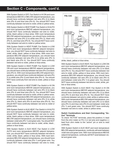
Section C - Components, cont’d.With System Switch in OFF, Fan Switch in HI ON and roomtemperature ABOVE or BELOW setpoint temperature, youshould have continuity between red wire (Pin 2) to blackwire (Pin 4) and blue wire (Pin 6). You should NOT havecontinuity between red wire to violet, white or yellow wires.With System Switch in HEAT PUMP, Fan Switch in HI AUTOand room temperature ABOVE setpoint temperature, youshould NOT have continuity between red wire to violet,white, black yellow or blue wires. With room temperatureBELOW setpoint temperature, you should have continuitybetween red wire (Pin 2) to white wire (Pin 3), black wire(Pin 4), and blue wire (Pin 6). You should NOT have continuitybetween red wire to violet or yellow wires.With System Switch in HEAT PUMP, Fan Switch in LOWAUTO and room temperature ABOVE setpoint temperature,you should NOT have continuity between red wire toviolet, white, black, yellow or blue wires. With room temperatureBELOW setpoint temperature, you should havecontinuity between red wire (Pin 2) to white wire (Pin 3)and black wire (Pin 4). You should NOT have continuitybetween red wire to violet, yellow or blue wires.With System Switch in HEAT PUMP, Fan Switch in LOWON and room temperature ABOVE setpoint temperature,you should have continuity between red wire (Pin 2) to blackwire (Pin 4). With room temperature BELOW setpoint temperature,you should have continuity between red wire (Pin2) to white wire (Pin 3) and black wire (Pin 4). You shouldNOT have continuity from red wire to violet, yellow or bluewires.With System Switch in HEAT PUMP, Fan Switch in HI ONand room temperature ABOVE setpoint temperature, youshould have continuity between red wire (Pin 2) to blackwire (Pin 4) and blue wire (Pin 6). You should NOT havecontinuity between red wire to violet, white or yellow wires.With room temperature BELOW setpoint temperature, youshould have continuity between red wire (Pin 2) to whitewire (Pin 3), black wire (Pin 4) and blue wire (Pin 6). Youshould NOT have continuity between red wire to violet oryellow wires.With System Switch in AUX HEAT, Fan Switch in HI AUTOand room temperature ABOVE setpoint temperature, youshould NOT have continuity between red wire to violet,white, black yellow or blue wires. With room temperatureBELOW setpoint temperature, you should have continuitybetween violet wire (Pin 1) and green wire. You should NOThave continuity between red wire to violet, white, black ,yellow or blue wires.With System Switch in AUX HEAT, Fan Switch in LOWAUTO and room temperature ABOVE setpoint temperature,you should NOT have continuity between red wire toviolet, white, black, yellow or blue wires. With room temperatureBELOW setpoint temperatures, you should havecontinuity between violet wire (Pin 1) and green wire. Youshould NOT have continuity between red wire to violet,44FIG. C43white, black, yellow or blue wires.With System Switch in AUX HEAT, Fan Switch in LOW ONand room temperature ABOVE setpoint temperature, youshould have continuity between red wire (Pin 2) to blackwire (Pin 4). You should NOT have continuity between redwire to violet, white, yellow or blue wires. With room temperatureBELOW setpoint temperature, you should havecontinuity between red wire (Pin 2) to black wire (Pin 4)and between violet wire (Pin 1) to green wire. You shouldNOT have continuity between red wire to violet, white, yellowor blue wires.With System Switch in AUX HEAT, Fan Switch in HI ONand room temperature ABOVE setpoint temperature, youshould have continuity between red wire (Pin 2) to blackwire (Pin 4) and blue wire (Pin 6). You should NOT havecontinuity between red wire to violet, white or yellow wires.With room temperature BELOW setpoint temperature, youshould have continuity between red wire (Pin 2) to blackwire (Pin 4) and blue wire (Pin 6) and between violet wire(Pin 1) and green wire. You should NOT have continuitybetween red wire to violet, white or yellow wires.Switch Combinations and their Corresponding “Active”TerminalsTo check “ACTIVE” terminals, place the positive (+) leadfrom the ohm meter on Pin 2 or red wire and negative (-)lead from ohm meter to the “active” pin or wire to readcontinuity.With System Switch in AUX HEAT and room temperatureBELOW setpoint temperature, continuity will exist betweenviolet wire and green wire. With room temperature ABOVEsetpoint temperature, continuity will NOT exist between violetand green wire.