8 – <strong>Parts</strong> Listing RSA32/RSM32 <strong>Parts</strong> <strong>Sheet</strong> #3600-4104_16_RSA32ps6. Remove Bearing (16) from the Bearing Plate (19):Solid Nut/Ball Nut: Remove the Retaining Ring (15) and pressthe Bearing (16) out of the Bearing Plate (19) as it is secured inplace with retaining compound.Roller Nut: Remove the Lock Ring (15) from the BearingPlate (19). Loctite is used on the Lock Ring (15) so heat may beneeded to make the loctite pliable. Press the two Bearings (16)out of the Bearing Plate (19) as they are secured in place withretaining compound.ASSEMBLY INSTRUCTIONS1. Sub-assemble Wiper (38) and Bearing (34) into Head (36):Install Wiper (38) with the lip on inside diameter facing outwardinto the groove in the Head (36). Press the Bearing Sleeve (34)from opposite end of Head (36) until it is flush to surface ofHead (36).2. Sub-assemble the Bearing (16) into Bearing Plate (19):Solid Nut/Ball Nut: Press Leadscrew Sleeve (17) into mainBearing (16). Apply Loctite 641 retaining compound to OD ofthe Bearing (16) and ID of the Bearing Plate (19) and installBearing (16) into the Bearing Plate (19). LMI only, install theSnap Ring (15).Roller Nut: Stack the 2 Bearings (16) onto each other so thenon-flanged inner races are touching. Press the LeadscrewSleeve (17) into both Bearings (16). Apply Loctite 641 retainingcompound to OD of both Bearings (16) and the ID bore of theBearing Plate (19). Install the bearing assembly into the BearingPlate (19) then install the Lock Ring (15). Use the flats on theLeadscrew Sleeve (17) while tightening the Lock Ring (15).3. Install Bearing Plate (19) assembly onto leadscrew/nut:LMI, Solid Nut/Ball Nut: Install Leadscrew (21) into theLeadscrew Sleeve (17) in Bearing Plate (19) assembly. ApplyLoctite 242 to the threads of the Leadscrew (21) then locateWasher (14) and Locknut (13) over Leadscrew (21). Torque theLock Nut (13) to 200 in-lbs, hold Leadscrew (21) in machinistvice as necessary.RP, Solid Nut/Ball Nut: (Reference parts list on page 6.) InstallLeadscrew (21) into the Leadscrew Sleeve (17) and applyLoctite 242 to the threads of the Leadscrew (21). Place Key (13)onto Leadscrew (21) and install the Pulley (12), Washer (11), andLock Nut (10) over Leadscrew (21). Torque Lock Nut (10) to 200in-lbs. Hold Leadscrew (21) in machinist vice as necessary.LMI, Rollerscrew: (Reference parts list on page 3.) Fromthe motor end of the Leadscrew/Roller Nut (21) slide the NutHousing Cover (22) onto the Leadscrew/Roller Nut (21) so it fitsover roller nut. Install the Leadscrew/Roller Nut (21) into theLeadscrew Sleeve (17) in Bearing Plate (19) assembly. Installthe Bearing Seal (45) and Spacer (14) onto Leadscrew/RollerNut (21) and secure using Lock Nut (13). Note: Lock Nut (13)requires special tool to install.4. Install nut with Nut Coupler/Housing (28) onto leadscrew/nut:Solid Nut/Ball Nut: Thread the Nut Assembly (28) onto theLeadscrew (21). Threaded end of the Nut Assembly (28) is awayfrom motor end of the Leadscrew (21).Roller Nut: NOTE: The roller nut must never be removedfrom the Leadscrew/Roller Nut (21). Align the slot in the NutHousing (28) with key on the roller nut on the Leadscrew/RollerNut (21) and slide Nut Housing (28) onto the roller nut from thenon-motor end of the Leadscrew/Roller Nut (21). Apply Loctite271 onto the ID threads of the Nut Coupler Cover (22). Fromthe motor end of the Leadscrew/Roller Nut (21), thread on NutHousing Cover (22) onto the Nut Housing (28). Make sure not toget any loctite on the leadscrew or roller nut.5. Assemble Bushing (30) onto non-motor end of leadscrew/nut:Solid Nut/Ball Nut: Slide the leadscrew Bushing (30),Bumper (31), Washer (32) onto non-motor end of theLeadscrew (21) and secure using Retaining Ring (33).Roller Nut: Slide the rollerscrew Bushing (30) onto theShoulder Bolt (31) and install Shoulder Bolt (31) onto end of theLeadscrew/Roller Nut (21).6. Grease leadscrew/nut and ID of the Thrust Tube (29) with thefollowing grease:Ball Nut/Bronze Nut Units: Grease w/ Mobil HP greaseSolid Nut Units: Grease w/ Christolube MCG #405Roller Nut Units: <strong>Tolomatic</strong> Grease #2744-90997. Install Thrust Tube (29) onto Nut Coupler/Housing (28):Apply Loctite 270 to OD threads on Thrust Tube (29) andassemble Thrust Tube (29) to Nut Coupler/Housing (28).8. Grease ID of Cylinder Body (20) w/ a coating of ChristolubeMCG #405 grease, and install leadscrew/nut assembly intothe Cylinder Body (20). *Make sure to orient Nut HousingBearing (25) with respect to tube the same as were removed.9. Attach Head (36) and Bearing Plate (19) assembly to theCylinder Body (20) and align prior to tightening:LMI, Solid Nut/Ball Nut:A. Align motor end Bearing Plate (19) assembly to CylinderBody (20) with Thrust Tube (29) retracted, and then tightenSocket Head Cap Screws (18).B. Align non-motor end Head (36) to Cylinder Body (20) withThrust Tube (29) extended, and then tighten Socket HeadCap Screws (37).RP, Solid Nut/Ball Nut:A. (See page 4, 5 parts list for this step.) Install the RPPlate (7) through Bearing Plate (18) to Cylinder Body (20)with Thrust Tube (29) retracted, and then tightening twoSocket Head Cap Screws (15) into the top two holes in theRP Plate (7). Install Retaining Ring (14).B. (See page 1, 2 parts list for this step.) Align non-motorend Head (36) to Cylinder Body (20) with Thrust Tube (29)extended, and then tighten Socket Head Cap Screws (37).RP, Roller Nut:A. (See page 6 parts list for this step.) Install the RP Plate (7)through Bearing Plate (18) to Cylinder Body (20) withThrust Tube (29) retracted, and then tightening two SocketHead Cap Screws (15) into the top two holes in the RPPlate (7).<strong>Tolomatic</strong> • URL: http://www.tolomatic.com • Email: help@tolomatic.com • Fax: (763) 478-8080 • Toll Free: 1-800-328-2174
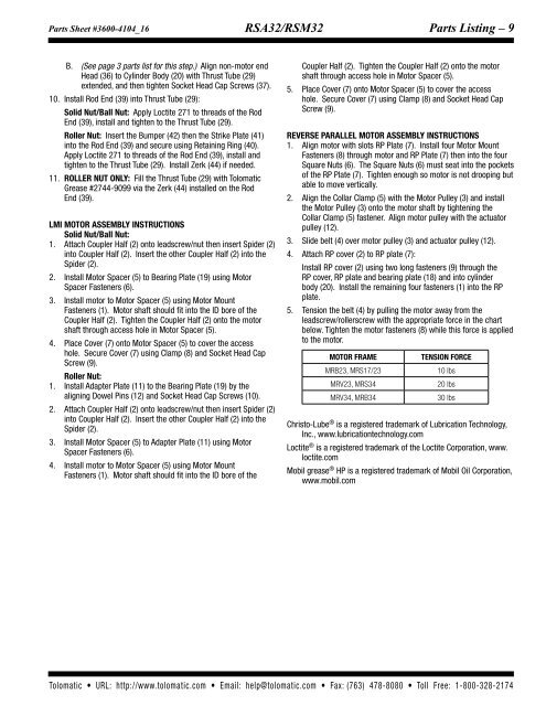
<strong>Parts</strong> <strong>Sheet</strong> #3600-4104_16_RSA32ps RSA32/RSM32 <strong>Parts</strong> Listing – 9B. (See page 3 parts list for this step.) Align non-motor endHead (36) to Cylinder Body (20) with Thrust Tube (29)extended, and then tighten Socket Head Cap Screws (37).10. Install Rod End (39) into Thrust Tube (29):Solid Nut/Ball Nut: Apply Loctite 271 to threads of the RodEnd (39), install and tighten to the Thrust Tube (29).Roller Nut: Insert the Bumper (42) then the Strike Plate (41)into the Rod End (39) and secure using Retaining Ring (40).Apply Loctite 271 to threads of the Rod End (39), install andtighten to the Thrust Tube (29). Install Zerk (44) if needed.11. Roller Nut only: Fill the Thrust Tube (29) with <strong>Tolomatic</strong>Grease #2744-9099 via the Zerk (44) installed on the RodEnd (39).LMI MOTOR ASSEMBLY INSTRUCTIONSSolid Nut/Ball Nut:1. Attach Coupler Half (2) onto leadscrew/nut then insert Spider (2)into Coupler Half (2). Insert the other Coupler Half (2) into theSpider (2).2. Install Motor Spacer (5) to Bearing Plate (19) using MotorSpacer Fasteners (6).3. Install motor to Motor Spacer (5) using Motor MountFasteners (1). Motor shaft should fit into the ID bore of theCoupler Half (2). Tighten the Coupler Half (2) onto the motorshaft through access hole in Motor Spacer (5).4. Place Cover (7) onto Motor Spacer (5) to cover the accesshole. Secure Cover (7) using Clamp (8) and Socket Head CapScrew (9).Roller Nut:1. Install Adapter Plate (11) to the Bearing Plate (19) by thealigning Dowel Pins (12) and Socket Head Cap Screws (10).2. Attach Coupler Half (2) onto leadscrew/nut then insert Spider (2)into Coupler Half (2). Insert the other Coupler Half (2) into theSpider (2).3. Install Motor Spacer (5) to Adapter Plate (11) using MotorSpacer Fasteners (6).4. Install motor to Motor Spacer (5) using Motor MountFasteners (1). Motor shaft should fit into the ID bore of theCoupler Half (2). Tighten the Coupler Half (2) onto the motorshaft through access hole in Motor Spacer (5).5. Place Cover (7) onto Motor Spacer (5) to cover the accesshole. Secure Cover (7) using Clamp (8) and Socket Head CapScrew (9).REVERSE PARALLEL MOTOR ASSEMBLY INSTRUCTIONS1. Align motor with slots RP Plate (7). Install four Motor MountFasteners (8) through motor and RP Plate (7) then into the fourSquare Nuts (6). The Square Nuts (6) must seat into the pocketsof the RP Plate (7). Tighten enough so motor is not drooping butable to move vertically.2. Align the Collar Clamp (5) with the Motor Pulley (3) and installthe Motor Pulley (3) onto the motor shaft by tightening theCollar Clamp (5) fastener. Align motor pulley with the actuatorpulley (12).3. Slide belt (4) over motor pulley (3) and actuator pulley (12).4. Attach RP cover (2) to RP plate (7):Install RP cover (2) using two long fasteners (9) through theRP cover, RP plate and bearing plate (18) and into cylinderbody (20). Install the remaining four fasteners (1) into the RPplate.5. Tension the belt (4) by pulling the motor away from theleadscrew/rollerscrew with the appropriate force in the chartbelow. Tighten the motor fasteners (8) while this force is appliedto the motor.Motor FrameMRB23, MRS17/23MRV23, MRS34MRV34, MRB34Tension Force10 lbs20 lbs30 lbsChristo-Lube ® is a registered trademark of Lubrication Technology,Inc., www.lubricationtechnology.comLoctite ® is a registered trademark of the Loctite Corporation, www.loctite.comMobil grease ® HP is a registered trademark of Mobil Oil Corporation,www.mobil.com<strong>Tolomatic</strong> • URL: http://www.tolomatic.com • Email: help@tolomatic.com • Fax: (763) 478-8080 • Toll Free: 1-800-328-2174


