OPERATOR'S MANUAL - The Baker Company Blog
OPERATOR'S MANUAL - The Baker Company Blog
OPERATOR'S MANUAL - The Baker Company Blog

You also want an ePaper? Increase the reach of your titles
YUMPU automatically turns print PDFs into web optimized ePapers that Google loves.
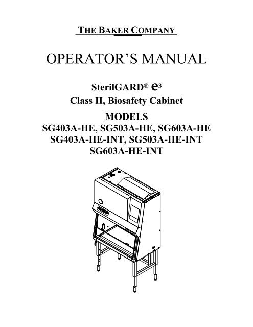
THE BAKER COMPANYOPERATOR’S <strong>MANUAL</strong>SterilGARD ® e 3Class II, Biosafety CabinetMODELSSG403A-HE, SG503A-HE, SG603A-HESG403A-HE-INT, SG503A-HE-INTSG603A-HE-INT
spatial data infrastructure (FIG, 1995; Tomlinson Associates Ltd., 1993). <strong>The</strong> basic premise ofthis paper is that maintenance of the digital cadastral map either in its support of, or as aconsequence of cadastral systems and in the current technological environment, is differentfrom the entities and processes involved in the analogue cadastral system.This paper confines itself to the digital spatial cadastral data and looks at the cadastral processas a system loosely bounded by the jurisdiction of the cadastral map. <strong>The</strong> main contention ofthe paper is that the maintenance of the digital cadastral map must be researched in thecontext of the entire cadastral system. Taking into account the needs and processes of all theentities in the cadastral system is the way to realise the goal of a single, jurisdiction wide digitalcadastral map which in time can become a survey accurate and multipurpose product.2. <strong>The</strong> cadastral process as a systemA single homogeneous state or nation wide cadastral product is the goal for any custodian ofthe digital cadastral map. <strong>The</strong> social and economic benefits of a single jurisdiction wide digitalcadastral map are undermined when multiple cadastral maps are being created and maintained.New technologies represent opportunities not previously available, not only to the custodians ofthe cadastral map, but also to all the participants in the cadastral process and the customers ofthe digital cadastral maps. Some jurisdictions have attempted to cost the process of keeping thedigital cadastral map up to date. <strong>The</strong> cost per parcel even for graphically accurate cadastralmaps is expensive (Jacoby 1996), while improving the accuracy of this digital product isestimated to be far more costly. Clearly there is a need to look anew at the cadastral mapmaintenance process to address these issues.<strong>The</strong> cadastral process of any country can be viewed as an information system and in fact muchof the literature refers to a jurisdiction’s cadastral system. This system includes two keycomponents or subsystems, a spatial component, the geometric description of the land parcels,linked to the textual component, records or registers, describing the nature of interests andownership of the land parcel (FIG, 1995). <strong>The</strong> intent in this paper is to review the spatialcomponent of the cadastral system, the creation and maintenance of the digital cadastral map,and view it as an information system with its constituent parts, namely data, processes, peopleor institutions, software and hardware. <strong>The</strong> spatial subsystem is considered as a subset of thecadastral system while still fully accounting for the constituent institutions that make up thecadastral systems of the western cadastral systems examined. <strong>The</strong> application of informationsystems analysis techniques requires an examination of the current systems from the initialcreation of the digital cadastral data by the surveyor, the other institutions involved in thecadastral system, to the intermediate or eventual customers of this spatial cadastral data Thiscan then be represented as a spatial data flow of that system (Effenberg and Williamson 1996).3. <strong>The</strong> cadastral map and its maintenanceObservation of the differences in the cadastral maps of between Europe and Australia or eventhe cadastral maps of the Australian states (PSMA 1996) clearly shows that there is no agreedcontent for the cadastral map let alone some consensus on data models. In Williamson andEnemark (1996) the cadastral map is shown as a product to service the often unique processesof a jurisdiction’s respective cadastral system, a system based on the cultural, social andeconomic history of that jurisdiction. Nevertheless it is worthwhile to attempt to define a basecontent for the cadastral map to support a cadastral system and to clearly define anddistinguish between upgrade and update in the cadastral map maintenance process.3.1 Content of the digital cadastral map<strong>The</strong> content of the digital cadastral map can ultimately only be determined by a carefulconsideration of the intended use of the digital cadastral map. Nevertheless to discuss themaintenance of the of the map it is necessary to define what data the cadastral map contains.<strong>The</strong> following is an attempt to broadly define a base cadastral map content for the purpose of
TABLE OF CONTENTSI – FUNCTION OF THE SterilGARD ® e 3 ....................................................................................................1SterilGARD ® e 3 Airflow and Base Features................................................................................................................................1Figure1, Airflow Inside Cabinet .................................................................................................................................................1Base Features ..............................................................................................................................................................................2Cabinet Pressure Plenums ...........................................................................................................................................................3Design Details ................................................................................................................................................................................3Motor / blower capacity..............................................................................................................................................................3Air balance adjustments..............................................................................................................................................................3ReadySafe Mode.........................................................................................................................................................................3Tested HEPA filters ....................................................................................................................................................................3Easy filter access.........................................................................................................................................................................3One-piece interior wall construction...........................................................................................................................................3Front access high velocity air slots .............................................................................................................................................4Towel guard ................................................................................................................................................................................4All-metal plenums.......................................................................................................................................................................4Removable recessed stainless steel work surface .......................................................................................................................4Drain pan ....................................................................................................................................................................................4Viewscreen..................................................................................................................................................................................4Work area lighting ......................................................................................................................................................................4Electronic ballast.........................................................................................................................................................................4Sponge armrest pad.....................................................................................................................................................................4UniPressure plenum....................................................................................................................................................................5Motor / Blower assembly............................................................................................................................................................5Cable ports ..................................................................................................................................................................................5UV light (Optional).....................................................................................................................................................................5Adjustable Cabinet Height (Optional) ........................................................................................................................................5Specifications.................................................................................................................................................................................6Weights:......................................................................................................................................................................................6Electrical Specifications..............................................................................................................................................................7Environmental Conditions ..........................................................................................................................................................8Symbols and Terminology..........................................................................................................................................................8II - PREPARING THE SterilGARD ® e 3 FOR USE .....................................................................................9Checking the Cabinet Upon Arrival ...........................................................................................................................................9<strong>The</strong> Uses of a Biological Safety Cabinet......................................................................................................................................9Installing the Cabinet ...................................................................................................................................................................9Location Within the Laboratory ...............................................................................................................................................10Venting into the Room..............................................................................................................................................................10Connecting the Exhaust for Ducting Outdoors.........................................................................................................................11Final Connections and Tests ......................................................................................................................................................13Auxiliary Wiring Options ..........................................................................................................................................................14Auxiliary Blower Switch Status Wiring Option .......................................................................................................................15Auxiliary Cabinet Monitoring Wiring Option ..........................................................................................................................15Auxiliary Cabinet Monitoring Wiring Option ..........................................................................................................................16III - PROPER CABINET USE ..................................................................................................................................................16III - PROPER CABINET USE ..................................................................................................................................................17Operator Controls ......................................................................................................................................................................17Figure 2, Operator Controls......................................................................................................................................................17Programmable Delay Off Time Function .................................................................................................................................18Alarm Conditions........................................................................................................................................................................19Start-up Procedure .....................................................................................................................................................................21Working in the Cabinet..............................................................................................................................................................21Reacting to Spills.........................................................................................................................................................................23Cable Ports ..................................................................................................................................................................................23Ultraviolet Germicidal Lamp (Optional)..................................................................................................................................23
Micro-Biological Decontamination............................................................................................................................................23(This Page Intentionally Left Blank).........................................................................................................................................25Recommended Decontamination Procedure (Formaldehyde)................................................................................................26Cleaning and Disinfecting Stainless Steel .................................................................................................................................32Simple Cleaning........................................................................................................................................................................32Disinfection...............................................................................................................................................................................32Using Ancillary Equipment........................................................................................................................................................33About the HEPA Filters .............................................................................................................................................................33Check the HEPA Filters Regularly (Recommended on an Annual Basis)................................................................................33IV - ONSITE CHECKS AND MAINTENANCE PROCEDURES...........................................................34<strong>The</strong> Airflow Balance ...................................................................................................................................................................34Filter Leak & Smoke Testing.....................................................................................................................................................35Filter leak test procedure – Down flow filter............................................................................................................................35Filter leak test procedure – Exhaust filter .................................................................................................................................36Airflow smoke pattern test........................................................................................................................................................36Electrical safety tests.................................................................................................................................................................36Maintenance Notes......................................................................................................................................................................37Cleaning the Work Area ...........................................................................................................................................................37Ultraviolet Germicidal Lamp (Optional) ..................................................................................................................................37Checking the Magnehelic Gauge or Optional Air Flow Monitor (AFM).................................................................................37Replacing the Cabinet Filters ....................................................................................................................................................37Accessing the down flow and exhaust filters............................................................................................................................38Changing the down flow filter ..................................................................................................................................................39Changing the exhaust filter .......................................................................................................................................................40Troubleshooting ..........................................................................................................................................................................42V – DISASSEMBLY INSTRUCTIONS.......................................................................................................44Appendix.........................................................................................................................................................46Replacement Parts List: .............................................................................................................................................................47General Arrangement Drawings:..............................................................................................................................................49SG403A-HE (Base Unit): .........................................................................................................................................................49SG403A-HE (With Channel Stand):.........................................................................................................................................50SG403A-HE (With Channel Stand & Casters):........................................................................................................................51SG403A-HE (With Hydraulic Lift): .........................................................................................................................................52SG403A-HE W/Canopy Exhaust Connection (With Channel Stand): .....................................................................................53SG503A-HE (Base Unit): .........................................................................................................................................................54SG503A-HE (With Channel Stand):.........................................................................................................................................55SG503A-HE (With Channel Stand & Casters):........................................................................................................................56SG503A-HE (With Hydraulic Lift): .........................................................................................................................................57SG503A-HE W/Canopy Exhaust Connection (With Channel Stand): .....................................................................................58SG603A-HE (Base Unit): .........................................................................................................................................................59SG603A-HE (With Channel Stand):.........................................................................................................................................60SG603A-HE (With Channel Stand & Casters):........................................................................................................................61SG603A-HE (With Hydraulic Lift): .........................................................................................................................................62SG603A-HE W/Canopy Exhaust Connection (With Channel Stand): .....................................................................................63SG403A-HE-INT (With Channel Stand):.................................................................................................................................64SG403A-HE-INT (With Channel Stand & Casters):................................................................................................................65SG403A-HE-INT (With Hydraulic Lift): .................................................................................................................................66SG603A-HE-INT (With Channel Stand):.................................................................................................................................67SG603A-HE-INT (With Channel Stand & Casters):................................................................................................................68SG603A-HE-INT (With Hydraulic Lift): .................................................................................................................................69Cable Port Illustration................................................................................................................................................................70Ladder Schematic: SGX03A-HE: (KB MOTOR DRIVE)......................................................................................................71Ladder Schematic: SGX03A-HE: (CONTROL RESOURCES MOTOR DRIVE)..............................................................73Ladder Schematic: SGX03A-HE-INT ......................................................................................................................................73Ladder Schematic: SGX03A-HE-INT ......................................................................................................................................74Ladder Schematic: SGX03A-HE-INT ......................................................................................................................................75Troubleshooting Guide for Standard Board ............................................................................................................................77
Stand Assembly Leg Extension Procedure ...............................................................................................................................79Channel Stand Installation or Removal Procedure.................................................................................................................83Replacing Fluorescent Lamps....................................................................................................................................................86Ultraviolet Lamp Replacement..................................................................................................................................................87Installation of Exhaust Transition System for SterilGARD ® e 3 Cabinets ..............................................................................88Exhausting Requirements for CEC:..........................................................................................................................................89(This page intentionally left blank)...........................................................................................................................................90Installation Instructions for CEC: .............................................................................................................................................91Installation Instructions for *FlexAIR Canopy Exhaust Connection (CEC) ............................................................................94Operating Instructions for *FlexAIR Canopy Exhaust Connection (CEC) ..............................................................................97(This page intentionally left blank).........................................................................................................................................100Airflow Monitor (AFM) Installation and Calibration: SterilGARD ® Free Standing Vented to Room............................101Vented to Room......................................................................................................................................................................101Installation & Calibration of Airflow Monitor (AFM) in Canopy Exhaust Connection ...................................................103Motor Control Adjustment Detail...........................................................................................................................................106NOTICE – O.S.H.A. Federal Regulation................................................................................................................................109Warranty ......................................................................................................................................................110
366D000M 1/4/2011I – FUNCTION OF THE SterilGARD ® e 3SterilGARD ® e 3 Airflow and Base FeaturesRoom air enters the front access opening of the cabinet at a minimum of 100 FPM [0.508m/sec] then entersthe front work surface perforation. Most of the HEPA filtered down flow air passes through a diffuser but someof the air is dumped down the back of the viewscreen creating a high velocity air curtain at the front accessopening. <strong>The</strong> HEPA filtered down flow air in the work area splits at the work surface. Some of the air enters therear work area perforation while the remainder of the air enters the front work surface perforation. <strong>The</strong> air ispulled through the drain pan area, up the rear and side wall plenums, to the cabinet blower. <strong>The</strong> air is thenpushed into the positive pressure plenum. At that point most of the air is pushed through the down flow HEPAfilter while the remainder is exhausted out the exhaust HEPA filter and through a perforated filter protector atthe top of the cabinet.[Reference Figure1]EXHAUSTEXHAUST HEPAFILTERPOSITIVE PRESSUREPLENUMDOWN FLOW HEPAFILTERINTAKE(ROOM AIR)= ROOM AIR= CONTAMINATED AIR= HEPA FILTERED AIRWORK AREADRAIN PAN AREAFigure1, Airflow Inside Cabinet1
366D000M 1/4/2011Base Features• Meets NSF 49 standard for Class II, biosafety cabinet.• HEPA filtration of air before it enters the work area.• Front accessibility to electrical components, lamp, blower, and filters.• Sliding viewscreen sloped 10 degrees for worker comfort.• Removable work surface and supports for easy cleaning of the drain pan area.• Down flow filter diffuser / protector.• Membrane switch control pad.• Auxiliary outlets (2).• Fluorescent lamp.• Petcock on left hand wall.• Padded armrest.CABINET BALANCING DAMPER CONTROLEXHAUST HEPA FILTERPROTECTORBLOWER OUTLETEXHAUST HEPA FILTERDOWN FLOW PLENUMDRESS PANELSDOWN FLOWHEPA FILTERMEMBRANE SWITCHCONTROL PADFLUORESCENT LAMP/ LIGHT CANOPYSLIDING VIEWSCREEN10 DEGREE SLOPEDOWN FLOWDIFFUSER / FILTERPROTECTORPETCOCK LOCATIONGFCI DUPLEXPADDED ARMRESTREMOVABLE WORKSURFACE AND SUPPORTS2
366D000M 1/4/2011Cabinet Pressure Plenums<strong>The</strong> cabinets work area is surrounded by negative pressure and all external seals are under negativepressure. All internal positive pressure plenum seals are surrounded by negative pressure plenums.Design DetailsMotor / blower capacityA motor / blower’s capacity is measured by its ability to provide a nearly constant volume of air asresistance increases because of filter loading. Verification by a simulated filter-loading test has established thatyour SterilGARD ® cabinet is capable of automatically handling more than a 200% increase in pressure dropacross the filter without reducing total air delivery more than 10%.Air balance adjustmentsYour new <strong>Baker</strong> cabinet has been built with a new motor controller that should not need adjustment in thefield. If any motor blower adjustments are thought to be needed please call 1-800-992-2537 and ask fortechnical support.<strong>The</strong>se cabinets have been built with an internal balancing damper that compensates for down flow andexhaust/intake imbalances. This damper may be adjusted only by a qualified technician who has had propertraining and has the proper equipment.ReadySafe Mode<strong>The</strong> “ReadySafe Mode” is a feature that reduces the total airflow and energy consumption of the cabinetwhen it is not being used. Operation of the cabinet in “ReadySafe Mode” maintains personnel, product andenvironmental protection. <strong>The</strong> “ReadySafe Mode” is activated when the sash reaches its fully closed positionand is indicated by reduced blower speed and the fluorescent lights automatically turning off. When the sash isreturned to safe operating height the cabinet airflow will return to its original set point. <strong>The</strong> fluorescent lightcan then be turned on. In order for the ReadySafe feature to be enabled there must be a jumper installed on J23of the control board. Further reference to connections on the control board can be found in the Auxiliary WiringOptions section of this manual, (Dwg 333E548 & 333E549).Tested HEPA filtersAll filters in the cabinet are scan-tested HEPA filters. <strong>The</strong>y are 99.99% effective on particles of 0.3 micronsize. Each filter is leak checked after installation to assure that there are no leaks greater than 0.01% of theupstream concentration.Easy filter accessFor convenience and ease of service, all filters are front accessible. <strong>The</strong> down flow and exhaust filters canbe removed through an access panel located behind the dress panels in the front of the cabinet. Only qualifiedtechnicians should replace filters.One-piece interior wall construction<strong>The</strong> interior side and rear work area walls are constructed from a single piece of 16-gauge stainless steel. It3
366D000M 1/4/2011has 7/16” [11.1mm] radius (rounded) corners to help prevent buildup of contaminants and aid in cleanup.Front access high velocity air slotsAt the intersection of both sidewalls and front access opening there are high velocity air slots. <strong>The</strong> purposeof the slots is to capture any particulate traveling near the sidewalls and access opening.Towel guard<strong>The</strong> towel guards are located under the work surface at the bottom rear and sides of the return-air plenums.Acting as a protective screen, integral to the interior walls, they help prevent wipes and other paper materialsfrom being drawn into the blower system. <strong>The</strong>y need to be kept clean at all times.All-metal plenums<strong>The</strong> plenums are constructed entirely of either carbon steel or stainless steel in order to provide strength,durability, air-tightness and resistance to deterioration.Removable recessed stainless steel work surface<strong>The</strong> work surface is constructed of corrosion resistant 16-gauge type 304 stainless steel, with a satin finishthat diminishes light reflection. It is recessed to retain spills and can be removed along with its supports to gainaccess to the drain pan.Drain pan<strong>The</strong> drain pan is designed with 7/16” [11.1mm] radius in all four bottom corners to facilitate cleaning anddisinfection. Drainage is provided by a 1/2” [12.7mm] diameter stainless steel ball valve located at the bottomof the drain pan.Viewscreen<strong>The</strong> cabinet’s 1/4” [6.35mm] safety plate glass sliding viewscreen may be opened to 20” [508.0 mm] (withoutarmrest) for placing of large items in the work area, and maybe fully closed for system shutdown or UV lightoperation. Note: the armrest must be properly re-installed prior to working in the cabinet.Work area lighting<strong>The</strong> work area is illuminated by two external fluorescent lamps which provide a minimum of 100 footcandlesof light at the work surface.Electronic ballast<strong>The</strong> SterilGARD ® features solid-state electronic ballasts for the fluorescent and UV (optional) lights. <strong>The</strong>seballasts increase reliability, efficiency, and service life with lower heat output.Sponge armrest pad<strong>The</strong> armrest pad is made out of EPDM sponge material and is resistant to most chemicals and UV exposure.It is held in place with a low tack adhesive so the pad can be easily removed for cleaning. It also can beautoclaved.4
366D000M 1/4/2011UniPressure plenumA telescoping all steel positive pressure plenum provides a more even clamping force on the HEPA filterframes and helps deliver the down flow air more uniformly. <strong>The</strong> plenum can be easily telescoped for quick filterchanging.Motor / Blower assembly<strong>The</strong> motor and blower are assembled on a slide plate. This allows the assembly to be easily removed fromthe positive pressure plenum for faster servicing or replacement.Cable portsOne cable port comes as a standard item on the right side wall, and one can also be added into the cabinet’sleft side wall as an option. It provides a way of introducing power and data cables, or siphoning tubes into thework area of the cabinet without having to go through the front viewscreen access opening. A plug is providedfor each port for use when the port is not being used or for when the cabinet is being decontaminated.UV light (Optional)<strong>The</strong> SterilGARD ® can be equipped with an ultraviolet light. <strong>The</strong> light is controlled by an on/off switch on thefront panel. [See Figure 2 Operator Controls].WARNING• Do not defeat interlock, UV light is hazardous!• Eyes and skin should not be exposed to direct ultraviolet light.• Ultraviolet light should not be relied upon as the sole decontaminating agent. Additional surfacedisinfection should be performed both before and after every cabinet use.• A biological safety cabinet acts as a supplement to good aseptic practices, not as a replacement.Ultraviolet lamps lose their effectiveness over time and should be replaced when the intensity at the worksurface drops below 40 microwatts per cm 2 at a wavelength of 253.5 x 10 -9 meters. Be sure to check regularly.Adjustable Cabinet Height (Optional)<strong>The</strong> Channel Stand has adjustable legs and leg levelers. <strong>The</strong> legs provide 6” [152.4mm] of heightadjustment and the leg leveler provides an additional 2.5” [63.5mm] of height adjustment.5
366D000M 1/4/2011SpecificationsWeights:UnitStand OptionsUnit WeightW/ StandWeight W/PackagingSterilGARD ® e 3Channel Stand 668 Lbs. [303 kg] 798 Lbs. [362 kg]SG403A-HE & Channel Stand with Casters 675 Lbs. [306 kg] 805 Lbs. [365 kg]SG403A-HE-INT Hydraulic lift 816 Lbs. [370 kg] 946 Lbs. [429 kg]SterilGARD ® e 3SG503A-HEChannel Stand 756 Lbs. [343 kg] 906 Lbs. [411 kg]Channel Stand with Casters 763 Lbs. [364 kg] 913 Lbs. [414 kg]Hydraulic lift 909 Lbs. [412 kg] 1059 Lbs. [480 kg]SterilGARD ® e 3Channel Stand 830 Lbs. [376 kg] 1000 Lbs. [454 kg]SG603A-HE & Channel Stand with Casters 837 Lbs. [380 kg] 1007 Lbs. [457 kg]SG603A-HE-INT Hydraulic lift 988 Lbs. [448 kg] 1158 Lbs. [525 kg]6
366D000M 1/4/2011Electrical SpecificationsAll electrical wiring to the cabinet should comply with the National Electrical Codeand any applicable Local Electrical Codes at the site of installation.A single dedicated circuit is required to power this cabinet. This circuit shall provide the protective earth groundfor the cabinet.<strong>The</strong> unit is furnished with one 14' power cord with an appropriate Listed/approved plug for the destinationcountry.<strong>The</strong> power cord is the Main Disconnect device for the unit. <strong>The</strong> unit should bepositioned in a manner that allows easy access to the power cord connection to theelectrical utility.<strong>The</strong> cabinet is provided with two outlets. <strong>The</strong> outlet(s) on this circuit are protected by a self-resetting circuitbreaker. <strong>The</strong> breaker allows 5A total on all outlets.Cabinet Ratings: SGxxxA-HE115V AC, 16A, 60Hz, Single Phase, Dedicated circuit.Typical current (less outlets) for SG403A-HE 4.0 – 6.0 AmpsTypical current (less outlets) for SG503A-HE 5.0 – 7.0 AmpsTypical current (less outlets) for SG603A-HE 5.0 – 8.0 Amps(Note: Actual current values will vary depending on cabinet configuration.)<strong>The</strong> cabinet is internally protected with a 250V, 20A Circuit breaker.Cabinet Ratings: SGxxxA-HE-INT220V AC, 13A, 50/60Hz, Single Phase, Dedicated circuit.Typical current (less outlets) for SG403A-HE-INT 2.0 – 3.0 AmpsTypical current (less outlets) for SG603A-HE-INT 4.0 – 5.0 Amps(Note: Actual current values will vary depending on cabinet configuration.)<strong>The</strong> Motor/Control circuit (less outlets) is protected by 6.3A, Time Delay Fuses<strong>The</strong> cabinet may be provided with an optional lift that requires 2 Amps intermittent duty.<strong>The</strong> lift duty cycle is 1 minute on, 9 minutes off.<strong>The</strong> cabinet may be provided with an optional UV lamp.<strong>The</strong> UV lamp and Fluorescent lamp are interlocked to prevent simultaneous operation.<strong>The</strong> cabinet may be provided with an optional 24V DC power supply for low voltage options.7
366D000M 1/4/2011Environmental Conditions<strong>The</strong> cabinet is designed for use in the following conditions:• Indoor use• Altitudes up to 2000 meters• Temperature range from 41° F (5°C) to 104° F (40°C)• Maximum relative humidity 80% for temperatures up to 88° F (31°C) decreasing linearly to50% at 104° F (40°C)• Main Supply voltage: Rated Voltage stated in Cabinet Ratings ±10%V AC• Transient over voltage according to Installation Category (OVERVOLTAGE CATEGORIES)II per UL/IEC61010-1, 2 nd Edition• Pollution Degree 2Symbols and TerminologyProtective Earth: Any terminal intended for connection to external protective conductor forprotection against electric shock in case of a fault.!General Caution: Refer to instruction manual for information regarding personnel and environmentprotection.8
366D000M 1/4/2011II - PREPARING THE SterilGARD ® e 3 FOR USEChecking the Cabinet Upon ArrivalUpon receipt of your new SterilGARD ® cabinet, first inspect the exterior of the crate, box and/or skid. Ifthere is any visible damage, that fact should be noted on the receiving slip and immediately reported to thedelivering carrier.Next, remove the outer packing material and inspect the cabinet itself. If any concealed damage is found itshould be reported to the delivery carrier. A claim for restitution should be filed within 15 days.<strong>The</strong> Uses of a Biological Safety Cabinet<strong>The</strong> SterilGARD ® has been designed to provide a work area which protects the experiment from theenvironment, and the environment and operator from the experiment. <strong>The</strong> laminar flow biological safetycabinet is designed for work with Biosafety Levels 1, 2 and 3 (low to moderate risk) agents as listed in <strong>The</strong>Center for Disease Control's "Biosafety in Microbiological and Biomedical Laboratories" (U.S. Department ofHealth and Human Services, Public Health Service, Centers for Disease Control and National Institutes ofHealth, U.S. Government Printing Office, Washington, D.C. 20402. (HHS publication number CDC 93-8395).Biosafety level 4 or extremely high risk agents should never be used in this cabinet, except in conjunctionwith a one-piece positive pressure personnel suit ventilated by a life support system within a high containmentfacility. Please consult your safety professional for a proper risk assessment.CAUTIONS* <strong>The</strong> use of any hazardous material in the cabinet requires that it be monitored by an industrialhygienist, safety officer, or other qualified individual.* Explosive or flammable substances should never be used in the cabinet unless a qualified safetyprofessional has evaluated the risk.* If hazardous biological work is to be performed, apply the enclosed biohazard decal. This is inaccord with OSHA regulations (volume 39, number 125, Part II).* If chemical, radiological or other non-microbiological hazards are present, be sure to employappropriate protective measures. Call upon a suitably trained individual to monitor the operation.Installing the CabinetInstallation of this cabinet should be carried out in accordance with appropriate OSHA regulationsand those other regulatory agencies having jurisdiction.To insure operator safety the cabinet must be installed and operated per the manufacturer’sinstructions.9
366D000M 1/4/20111. Remove the strapping that holds the cabinet to the pallet.2. Remove the cabinet from the skid with a forklift or other available equipment.3. Move the cabinet into the laboratory room. Remove all tape, plastic wrap and other packaging materialson the cabinet.4. Remove the ¼-20 hex head screws that attach the weight box closure panel located on the right side ofthe cabinet. <strong>The</strong> counterweight is located inside the right side panel of the cabinet. Remove all tape,plastic wrap, and other packaging materials inside the panel. Remove two ¼-20 hex head shippingscrews that hold the viewscreen counterweight from moving. <strong>The</strong> counterweight is located inside theright side panel of the cabinet. Verify that the view screen moves freely, and re-install the right side endpanel.5. Change out shipping hardware with ¼-20 thumb screws provided. A drawing showing the location ofthe shipping hardware on the cabinet is provided.6. <strong>The</strong> cabinet drain valve, stand adjustable leg levelers, and exhaust filter guard are shipped with the unitin a small cardboard box.7. Install the drain valve to the threaded pipe nipple. <strong>The</strong> nipple is located on the left underside of thecabinet drain pan.8. Be sure to remove the protective material covering the cabinet exhaust opening.9. If the cabinet vents its air directly into the laboratory room instead of ducting it outside, install theexhaust filter guard on top of the cabinet exhaust opening using the hardware provided.10. Follow the base stand assembly and adjustment instructions provided in the appendix of this manual toset the cabinet to the work surface height desired.11. Position the cabinet in its desired location within the laboratory room.Location Within the LaboratoryProper placement within the laboratory is essential. <strong>The</strong> ideal location for any biological safety cabinetis in a dead-end corner of the laboratory away from personnel traffic, vents, doors, windows, and any othersources of disruptive air currents. Published research from <strong>The</strong> <strong>Baker</strong> <strong>Company</strong> and unpublished testsperformed at the National Cancer Institute show that if a draft or other disruptive air current were to exceed theintake velocity of the cabinet, contamination can enter the work area or escape from it (for more information,contact <strong>Baker</strong>).If the cabinet exhausts air into the laboratory instead of venting to the outside, it is important that there isadequate space between the top of the cabinet and the ceiling. A solid ceiling located too close to the exhaustfilter will restrict the air and limit the intake velocity. <strong>The</strong> exhaust filter guard, an inverted “V” shapedperforated steel plate included with your SterilGARD ® cabinet, will provide the necessary distance betweenexhaust opening and ceiling. If the filter guard is not installed, the cabinet exhaust opening should be no closerthan 3” [76.2mm] from the ceiling, to enable proper airflow. Consult with our Customer Service Departmentfor the implications of this, and for alternatives.Venting into the Room1. Never use the top of the cabinet or the work area for storage purposes.2. Never use flammable, explosive or toxic vapors/gases, or substances which generate them, unless aqualified safety professional has evaluated the risk. <strong>The</strong> filters only remove particulates and not gases.3. Keep the exhaust filter guard on the cabinet. It will help protect the filter from objects being dropped onit and keep the cabinet spaced from the ceiling or other objects so it can exhaust properly.10
366D000M 1/4/2011CabinetModelSG403A-HE& INTSG503A-HESG603A-HE& INT*Air VentedNSF SashNSFinto RoomClass II HeightListed (Approximate)Type (Inches)(CFM)A2 8” [203.2mm] YES 285 [135 L/sec]A2 10” [254mm] YES 355 [168 L/sec]A1 12” [304.8mm] N/A 390 [184 L/sec]A2 8” [203.2mm] YES 355 [168 L/sec]N/A N/A N/A N/AA2 12” [304.8mm] YES 550 [260 L/sec]A2 8” [203.2mm] YES 455 [215 L/sec]A2 10” [254mm] YES 545 [257 L/sec]A1 12” [304.8mm] N/A 604 [285 L/sec]* - Includes air entering around perimeter of viewscreen, and air entering the front access openingConnecting the Exhaust for Ducting OutdoorsCabinet Venting into the RoomWhenever possible, the cabinet exhaust should be canopy connected to its own separate exhaust system. Ifit must be ducted into a ganged exhaust system, make sure that the system is not a recirculating one. <strong>The</strong>building exhaust system should contain provisions to adjust the building system flow and pressure.<strong>The</strong> connection between the cabinet and the building exhaust duct is a 10” [254mm] diameter CanopyExhaust Connection (CEC). It mounts directly over the exhaust filter and includes an access panel for leakchecking the exhaust filter. We recommend having a decon box and decon seal plate for the CEC to seal thecabinet during decontamination.CabinetModelSashHeight(Inches)Exhaust Flow Range(Approximate)(CFM)*Suction Min/Max(Inches W.C.)SG403A-HE& INTSG503A-HESG603A-HE& INT8” [203.2mm] 322 / 520 [152 / 245 L/sec] 0.05 / 0.25 [12.4 / 62.3 Pa]10” [254mm] 401 / 585 [189 / 276 L/sec] 0.08 / 0.30 [19.9 / 74.7 Pa]12” [304.8mm] 438 / 614 [207 / 290 L/sec] 0.09 / 0.40 [22.4 / 99.6 Pa]8” [203.2mm] 412 / 680 [194 / 321 L/sec] 0.10 / 0.35 [24.9/ 87.2Pa]N/A N/A N/A12” [304.8mm] 618 / 770 [292 / 363 L/sec] 0.20 / 0.40 [49.8 / 99.6 Pa]8” [203.2mm] 490 / 754 [231 / 356 L/sec] 0.15 / 0.40 [37.4 / 99.6 Pa]10” [254mm] 613 / 914 [289 / 431 L/sec] 0.20 / 0.50 [49.8 / 124.5 Pa]12” [304.8mm] 665 / 1015 [314 / 479 L/sec] 0.20 / 0.50 [49.8 / 124.5 Pa]* NOTE: Water column suction is measured directly above the cabinet exhaust outlet before any dampers, elbows or other restrictions.Exhaust Requirements for a CEC11
366D000M 1/4/2011<strong>The</strong> *FlexAIR is another type of CEC that has a 12” [304.8mm] diameter connection with a 10” [254mm]diameter spun inner baffle. It mounts directly over the exhaust filter and has flaps to reduce the amount of roomair being exhausted through the CEC. <strong>The</strong> front flap has a sensor that detects when the flap opens during lowduct exhaust conditions and triggers an alarm in the cabinet.VentToRoomCFM[L/SEC]FlexAirExhaustCFM[L/SEC]8”[203mm]Dia. DuctFlexAir Static PressureRequired (“W.C.[PA])10”[254mm] Dia.Duct12”[305mm] Dia.DuctMin Max Min Max Min Max Min MaxSG403A-HE8”[203mm]Access Opening10”[254mm]Access Opening12”[305mm] A1Access Opening12”[305mm] A2Access OpeningSG503A-HE8”[203mm]Access Opening12”[305mm]Access Opening285[135]355[168]390[184]404[191]355[168]550[260]290[137]360[170]400[189]415[196]360[170]560[265]663[313]701[331]820[387]871[411]700[331]850[402]-0.10[-25]-0.15[-38]-0.16[-40]-0.17[-42]-0.15[-37]-0.22[-55]-0.32[-80]-0.62[-155]-0.74[-185]-0.75[-182]-0.62[-155]-0.74[-185]-0.04[-10.0]-0.05[-13]-0.07[-18]-0.07[-15]-0.05[-13]-0.09[-23]-0.17[-43]-0.18[-45]-0.19[-48]-0.30[-75]-0.16[-40]-0.24[-60]-0.03[-8]-0.04[-10]-0.04[-10]-0.05[-12]-0.04[-10]-0.07[-18]-0.08[-20]-0.10[-25]-0.17[-43]-0.25[-62]-0.12[-30]-0.17[-43]SG603A-HE8”[203mm]Access Opening10”[254mm]Access Opening12”[305mm] A1Access Opening12”[305mm] A2Access Opening455[215]545[257]604[285]611[288]460[217]550[260]614[290]644[304]845[399]945[446]990[468]1114[526]-0.15[-38]-0.20[-50]-0.28[-70]-0.30[-75]-0.74[-185]-0.78[-195]-0.78[-195]-0.79[-197]-0.07[-18]-0.11[-28]-0.13[-33]-0.14[-35]-0.18[-45]-0.24[-60]-0.35[-88]-0.36[-90]-0.06[-15]-0.09[-23]-0.10[-25]-0.11[-27]-0.13[-33]-0.16[-40]-0.25[-63]-0.30[-75]* <strong>The</strong> FlexAIR CEC is Patent Pending.** NOTE: Water column suction is measured directly above the cabinet exhaust outlet before any dampers, elbows or other restrictions.Exhaust Requirements for a *FlexAIR CEC12
366D000M 1/4/2011Final Connections and Tests1. <strong>The</strong> plumbing connection to the service petcocks must be made with great care because the effluentfrom a safety cabinet may be biologically hazardous. When present, petcocks are piped within thecabinet. <strong>The</strong> external connection uses 3/8” compression fitting at the rear, top, or bottom of the cabinetouter sidewall seal panel. Qualified personnel with proper materials and technique should makeconnection to plant utilities per NFPA. Flammable gas should not be piped into any cabinet. However,if the risk is professionally evaluated and a decision is made to install a flammable gas petcock, then anemergency shut-off valve should be situated in an accessible location outside the cabinet.2. Connect to dedicated power supply circuit as described in the “Electrical Specifications” section of thismanual.3. Thoroughly clean the interior of the cabinet. Locate the viewscreen at the correct opening height (8”,10” or 12” [203.2mm, 254mm or 304.8mm]).NOTE: See Section III - PROPER CABINET USE “Operator Controls” for information regardingsteps 4, 5, & 6 below.4. Turn on the Blower. <strong>The</strong> indicator light will illuminate and the running blower will make an audiblesound.5. Turn on the Fluorescent Light. <strong>The</strong> indicator light will illuminate along with the interior work area.6. Lower the viewscreen to its fully closed position and turn on the UV light (if equipped) to make sure itis operational.7. Although all units are carefully tested at the factory, it is advisable that certain other checks are madeon-site by a qualified technician after installation. <strong>The</strong>se include testing the filters for leaks andchecking the air found in Section 4, “On-site Checks and Maintenance”.8. It is recommended that all personnel who will be using the cabinet study this manual to learn how touse the cabinet effectively. For additional start up and use procedures, reference Section III, ProperCabinet UseFOR MORE INFORMATIONFor a complete listing of articles, papers, and reports related to containment, clean air products and safety, contact<strong>The</strong> <strong>Baker</strong> <strong>Company</strong> for our complete Bibliography or visit our website at www.bakerco.com13
366D000M 1/4/2011Auxiliary Wiring OptionsWhen the customer wants to monitor additional conditions in the unit, they can order the optional CabinetMonitor Wiring Package (333E549). This option will include the wiring and hardware for the Blower SwitchStatus Wiring Package (333E548) plus wiring for connection to the Blower Operational Status relay and theSash Alarm Status Relay. <strong>The</strong>y can choose to connect to one or more of these relays for monitoring or controlof external systems.14
366D000M 1/4/2011Auxiliary Blower Switch Status Wiring Option15
366D000M 1/4/2011Auxiliary Cabinet Monitoring Wiring Option16
366D000M 1/4/2011III - PROPER CABINET USEit.A biological safety cabinet is a valuable supplement to good sterile technique, but is not a replacement forIf the cabinet is not understood and operated correctly it will not provide an adequateprotective barrier. To insure operator safety the cabinet must be installed andoperated per the manufacturer’s instructions.All activities that are to be performed in your cabinet should first be approved by a competent professional,such as an industrial hygienist or safety officer, to make sure that the cabinet is appropriate for the work it willbe required to do. This person should monitor the cabinet and its operating personnel at regular intervals to seethat it is being used correctly.In order to keep the interior work area clean and free of particulates, all <strong>Baker</strong> biosafety cabinets aredesigned for continuous operation. If the blower is turned off, the work area will become contaminated withroom air. <strong>The</strong>refore it is recommended that the blower be left on at all times.Operator Controls<strong>The</strong> operator controls with indicators are arranged on the front electrical panel of the cabinet. A number ofswitches are arranged in a single membrane switch assembly. [Reference Figure 2]UV LightOn / OffFluorescent LightOn / OffDuplex OutletsOn / OffBlowerOn / OffAlarm Mute /Sash Level AlarmIndicatorLightsNote: See the following section for Programmable Delay off Time FunctionsFigure 2, Operator Controls17
366D000M 1/4/2011• Ultraviolet (UV) Light On / Off [Optional] – This switch controls the UV Light inside the work area ifthe UV Light option is installed. <strong>The</strong> viewscreen must be fully closed before the UV light will turnon. <strong>The</strong> Fluorescent Light and the UV Light are interlocked. When the viewscreen is closed, turningthe UV Light On will automatically turn the Fluorescent Light Off. Turning the Fluorescent Light Onwill automatically turn the UV Light Off. <strong>The</strong> UV light will automatically shut off if the viewscreen isopened. A yellow indicator light located below the switch will illuminate when the switch is on.• Fluorescent Light On / Off – This switch controls operation of the Fluorescent Light. <strong>The</strong> cabinetblower must be on for the Fluorescent Light to operate. <strong>The</strong> Fluorescent Light and the UV Lightare interlocked. When the viewscreen is closed, turning the UV Light On will automatically turn theFluorescent Light Off. Turning the Fluorescent Light On will automatically turn the UV Light Off. ABlue indicator light located below the switch will illuminate when the switch is on.• Duplex Outlets On / Off – This switch controls the duplex outlets in the work area. A Blue indicatorlight located below the switch will illuminate when the switch is on.• Blower On / Off – This switch controls the power to the cabinet blower. A Green indicator light locatedbelow the switch will illuminate when the switch is on.• Alarm mute / Sash level alarm – For normal operation, the viewscreen must be placed at the allowableopening of 8”, 10” or 12” [203.2mm, 254mm or 304.8mm]. <strong>The</strong> sash alarm will be activated wheneverthe viewscreen is at a potentially unsafe position. To mute the audible alarm, press the alarm mutebutton. <strong>The</strong> indicator light located below the switch will continue to flash. After five minutes, if theconditions persist, the alarm will sound again to remind you to reposition the viewscreen to its properlevel. You may press the alarm reset switch again to mute the audible alarm for an additional fiveminutes.Programmable Delay Off Time Function<strong>The</strong> following procedure can be used to program a Delay Off time for UV, outlets, or fluorescent lights:NOTE - <strong>The</strong> function to be programmed should be in the OFF condition before you start programming.15 minute increment programming:1. Press and hold the pushbutton of the device you want to program.2. In about 3 seconds you will hear a short ‘beep’. This indicates that you have turned the deviceON, are in the programming mode for the device, and have programmed it to turn OFF in 15minutes. Release the pushbutton.3. Each subsequent press of the device pushbutton while in the programming mode will add 15minutes to the Delay Off time. (e.g. pressing the pushbutton 3 additional times would set thedelay to 60 minutes, 15 min. initially plus 3 x 15 minutes additional delay times).4. <strong>The</strong> device control will remain in the programming mode for about 4 seconds if the pushbuttonis not pressed.5. Once the programming mode for the device has ended the device can be turned OFF normally,if desired, by pressing the device pushbutton.6. <strong>The</strong> programmed device will turn OFF automatically at the end of the Delay Time.7. Each time a programmed device is turned off manually or automatically the programming iscleared and must be reentered, if desired.18
366D000M 1/4/20111 hour increment programming:1. Press and hold the pushbutton of the device you want to program.2. In about 3 seconds you will hear a short ‘beep’. Continue to hold the pushbutton. In about anadditional 3 seconds you will hear a longer ‘beep’. This indicates that you have turned thedevice ON, are in the programming mode for the device, and have programmed it to turn OFFin 1 hour. Release the pushbutton.3. Each subsequent press of the device pushbutton while in the programming mode will add 1hour to the Delay Off time. (e.g. pressing the pushbutton 3 additional times would set the delayto 4 hours, 1 hour initially plus 3 x 1 hour additional delay times).4. <strong>The</strong> device control will remain in the programming mode for about 4 seconds if the pushbuttonis not pressed.5. Once the programming mode for the device has ended the device can be turned OFF normally,if desired, by pressing the device pushbutton.6. <strong>The</strong> programmed device will turn OFF automatically at the end of the Delay Time.7. Each time a programmed device is turned off manually or automatically the programming iscleared and must be reentered, if desired.Alarm ConditionsStandard cabinets utilize the sash alarm; however three more alarms are also indicated. Below arebrief descriptions of each of the alarm conditions that may be present on your cabinet. Additionalinformation can be found by referencing the Standard Electrical Board Troubleshooting Guide (Dwg-503E500) in the appendix of this manual.<strong>The</strong> sash alarm occurs when the viewscreen is not at a safe operating position, and alerts the userwith a visual and audible alarm once per second. <strong>The</strong>re is a 3 second delay before the alarm activates,to allow the end user time to move between safe operating positions. Pressing the mute button on thekeypad will stop the audible alarm, however the visual alarm will continue until the viewscreen isplaced at an appropriate level. If the sash position is not corrected, the audible alarm will return.<strong>The</strong> FlexAIR alarm, (optional components required) occurs when the front flap on the CEC opensdue to low exhaust air flow. A visual and audible alarm, twice per second, will alert users of thisundesirable operating condition. <strong>The</strong> FlexAIR alarm can be muted, however a visual alarm will remainuntil the problem is resolved. If the flex air exhaust system has not been corrected, the audible alarmwill return. Placing a jumper on J21 on the board causes the FlexAIR alarm to latch until it isacknowledged by an operator pressing the mute button. If no jumper is placed on J21, the alarm willclear once proper exhaust flow resumes.<strong>The</strong> Power / Processor Fault, occurs when the system experiences a power outage or the processorhas a fault. This alarm is enabled by placing a jumper on J22 of the control board. An indication ofthis fault is a visual and audible alarm of three 1 second alarms followed by a two second delay. Thiscycle is repeated until the alarm condition is cleared by pressing the mute key. Relay K4 will beinactive with LED 14 OFF when in alarm, and energized with LED 14 ON when no alarm is present.19
366D000M 1/4/2011<strong>The</strong> Double Proximity Fault alarm occurs when both proximity sensors are activated. A visual andaudible alarm four times per second indicates this fault condition. Below is a table which will help youto determine which proximity switch is at fault:ConditionFaulty Proximity SwitchView Screen ClosedLED 2 On (Normal )LED 1 OnUpper Limit Prox SwitchView Screen Open @ Safe operating positionLED 1 On (Normal )LED 2 OnLower Limit Prox SwitchView Screen Open (Not in safe operating position)LED 1 OnLED 2 OnBoth Prox Switches20
366D000M 1/4/2011Start-up Procedure1. If the cabinet has not been left running continuously, turn on the blower. An indicator lightlocated below the switch will illuminate when the switch is on and the running blower willmake an audible sound. Check the readings on the Magnehelic gauge, it should read a pressureconsistent with the last time the cabinet was on.2. Turn on the Fluorescent Light. <strong>The</strong> indicator light will illuminate along with the interior workarea. (NOTE: <strong>The</strong> Fluorescent Light will not come on unless the blower switch is on. <strong>The</strong>Fluorescent Light and UV Light are interlocked so they cannot operate simultaneously.)3. Check to determine that the drain valve is in the closed position or the drain coupling iscapped.4. If your cabinet has been purchased with the optional Ultraviolet Light (UV), lower theviewscreen to its fully closed position and turn the UV light on to make sure it is operational.(NOTE: <strong>The</strong> UV light option features an interlock that prohibits its operation unless theviewscreen is fully closed. <strong>The</strong> Fluorescent Light and UV Light are also interlocked sothey cannot operate simultaneously.)5. Wipe down the interior area of the cabinet with surface disinfectant. NOTE: Somedisinfectants, such as bleach or iodine, may corrode or stain the steel surfaces. Goodpractice is to thoroughly clean the surface afterward with a detergent and rinse withsterile water to prevent corrosion.6. Place all materials to be used for the next procedure inside the cabinet on the solid worksurface. Disinfect the exterior of these materials prior to placing them on the work surface.Everything required (and nothing more) should be placed in the cabinet before beginning yourwork so that nothing passes in or out through the air barrier, until the procedure is completed.Implements should be arranged in the cabinet’s work area in logical order so that clean anddirty materials are segregated, preferably on opposite sides of the work area. Blocking the frontand rear perforated grilles must be avoided. If wipes or absorbent towels are used on the worksurface, be sure to keep them away from the grilles.7. After your equipment is in place inside the cabinet, adjust the sliding viewscreen so it is open tothe correct opening height (8”, 10” or 12” [203.2 mm, 254mm, or 304.8mm]). An alarm willsignal if you are not at the proper opening. This is important to maintain proper cabinet airflow.8. Insure that the padded armrest assembly is properly installed. You can begin working in thecabinet after it has run for at least three minutes with the viewscreen in the proper position.Working in the Cabinet1. Hands and arms should be washed thoroughly with germicidal soap both before and after work in thecabinet. Operators are encouraged to wear long-sleeved gowns or lab coats with tight-fitting cuffs andsterile gloves. This minimizes the shedding of skin flora into the work area and protects hands andarms from contamination.2. Perform all work on the depressed area of the solid work surface. Work with a limited number of slowmovements. Since all of the equipment you need is already in the cabinet, it will not be necessary tomove your arms in and out through the air barrier.21
366D000M 1/4/20113. Because opening and closing doors in the laboratory causes air disturbance which might interfere withcabinet airflow, this kind of activity should be kept to a minimum while the cabinet is in use. Personnelshould also avoid walking by the front of the cabinet while it is in use.4. Avoid using floor-type pipette discard canisters. It is important that your used pipettes be discardedinto a tray or other suitable container inside the cabinet. This reduces the temptation to move in and outof the work area unnecessarily.5. Because of the restricted access, pipetting within the cabinet will require the use of pipetting aids.6. Use good aseptic technique. Procedures done with good technique and proper cabinet methods will notrequire the use of a flame. If, however, a safety officer approves the use of flame after evaluating thecircumstances, then a burner with a pilot light such as the "Touch-O-Matic" should be used. Place it atthe rear of the work area where the air turbulence caused by the flame will have the least possibleeffect. Flame disturbs the unidirectional airstream and also contributes to the heat load. If the cabinetblower is unintentionally turned off, the flame could also damage a filter.7. Tubing for a burner within the cabinet should be resistant to cracking or puncture. Material such asTygon tubing is not acceptable for this use.8. Never operate your cabinet while the viewscreen alarm indicator is on. <strong>The</strong> operating position ofthe sash provides an 8”, 10” or 12” [203.2mm, 254mm or 304.8mm] access opening (depending on unitconfiguration). This restricted opening permits optimum operating conditions for the cabinet. Becauseoperators will not all be the same height, it is suggested that the operator use a chair that may beadjusted for height.9. After a procedure has been completed, all equipment that has been in contact with the research agentshould be enclosed, and the entire surface decontaminated. Trays of discarded pipettes and glasswareshould be covered. <strong>The</strong> cabinet should then be allowed to run for at least three minutes with no activityso that the airborne contaminants will be purged from the work area. Next, make sure that allequipment is removed from the cabinet.10. After you have removed all materials, culture apparatus, etc., decontamination of the interior surfacesshould be repeated. Check the work area carefully for spilled or splashed nutrient that might supportbacterial growth. Never use the cabinet to store supplies or laboratory equipment.11. We recommend that the cabinet be left running continuously to ensure containment and cleanliness.When the cabinet is not in use, the “ReadySafe Mode” can be engaged to reduce energy consumptionby fully closing the sash. <strong>The</strong> blower speed is reduced and the fluorescent lights automatically turn off.<strong>The</strong> sash alarm will be silenced when the sash is in the fully closed position. When the sash is returnedto safe operating height, the cabinet returns to normal operation and the lights can be turned on again.22
366D000M 1/4/2011Reacting to SpillsSpills should be cleaned immediately to prevent cross contamination to the work and to avoid any damage tothe stainless steel surfaces.It is recommended that the researcher, in coordination with their consulting safety professional, have a writtenplan available in case of an accidental exposure or spill. <strong>The</strong> safety plan should include all of the emergencyprocedures to be followed in the event of an accident. All employees who use the cabinet should be familiarwith the safety plan.Cable PortsOne cable port comes as a standard item on the right side wall, and one can also be added into the cabinet’sleft side wall as an option. <strong>The</strong>y provide a way of introducing power and data cables, or siphoning tubes intothe work area of the cabinet without having to go through the front viewscreen access opening. A plug isprovided for each port, when the port is not being used or for when the cabinet is being decontaminated.It is important not to overload the port with too many cables/tubing (Approx a bundle 1 1/8” in dia. Max.).Cables/tubing in the work area need to be suspended on cable hooks provided. <strong>The</strong> hooks are located along theinterior rear wall. This keeps the cables/tubing from affecting the airflow in the work area and placing unwantedstress on the cable port gaskets. [Reference Cable Port Illustration in appendix]Ultraviolet Germicidal Lamp (Optional)<strong>The</strong> SterilGARD ® can be provided with an optional ultraviolet light. <strong>The</strong> light is controlled by an on/offswitch on the front panel. [See Figure 2]. <strong>The</strong> UV light will not operate unless the viewscreen is completelydown, and the fluorescent light is off.(NOTE: Germicidal lamps are designed to emit UVC radiation because of its ability to kill bacteria. In humans,UVC is absorbed in the outer dead layers of the epidermis. Accidental overexposure to UVC can cause cornealburns, commonly termed welders' flash, and snow blindness, and severe sunburn. While UVC injury usuallyclears up in a day or two, it can be extremely painful.)WARNING• UV light is hazardous, Do not defeat interlock!• Eyes and skin should not be exposed to direct ultraviolet light.• Ultraviolet light should not be relied upon as the sole decontaminating agent. Additional surfacedisinfection should be performed both before and after every cabinet use.• A biological safety cabinet acts as a supplement to good aseptic practices, not as a replacement.Ultraviolet lamps lose their effectiveness over time and should be replaced when the intensity at the worksurface drops below 40 microwatts per cm 2 at a wavelength of 253.5 x 10 -9 meters. Be sure to check regularly.Micro-Biological DecontaminationWhenever maintenance, service, or repairs are needed in a contaminated area of your cabinet, the cabinetmust first be decontaminated by an appropriate agent. <strong>The</strong> National Institute of Health, National CancerInstitute and the Centers for Disease Control have all recommended the use of formaldehyde gas for mostmicrobiological agents. Its application requires individuals who are experienced in the decontamination of23
366D000M 1/4/2011cabinets, since the gas itself is toxic.A good reference for this procedure is NSF/ANSI Standard 49-2007 ANNEX G “RecommendedMicrobiological decontamination Procedure”, NSF International, 789 North Dixboro Road, P.O. Box 130140,Ann Arbor, Michigan 48113-0140.24
366D000M 1/4/2011(This Page Intentionally Left Blank)25
366D000M 1/4/2011Recommended Decontamination Procedure (Formaldehyde)WARNINGOnly qualified technicians shall perform this procedure.Whenever maintenance, service or repairs are needed in a contaminated area of your cabinet, the cabinet mustfirst be decontaminated by an appropriate agent. <strong>The</strong> National Institute of Health, National Cancer Institute andthe Centers for Disease Control have all recommended the use of formaldehyde gas for most microbiologicalagents. Its application requires individuals who are experienced in the decontamination of cabinets, since thegas itself is toxic.A good reference for this procedure is NSF/ANSI Standard 49-2007 ANNEX G “RecommendedMicrobiological decontamination Procedure”,NSF International, 789 North Dixboro Road, P.O. Box 130140,Ann Arbor, Michigan 48113-0140.Whichever gas you choose, make sure that you have the proper safety equipment (gas masks, protectiveclothing, etc.) within easy reach. In addition, you will want to be sure that the gas you are using will beeffective against all of the biological agents within the cabinet. When you have decided which gas to use, postthe antidote to it in a visible and nearby location. <strong>The</strong> volume of the SG403A HE, SG503A HE, & SG603A HEcabinets are 49 ft 3 , 62 ft 3 , & 78 ft 3 [1.39 m 3 , 1.75 m 3 , & 2.21 m 3 ] respectively. Provide the correct amountof decontaminating gas for this volume.WARNINGCarcinogens and other toxins present a unique chemical deactivation problem and the standard biologicaldecontamination will not, of course, be effective against chemicals or other non-biological materials. Withmaterials of this kind, consult a qualified safety professional.1. Surface-disinfect the inside of the window and all other surfaces on the viewscreen assembly.2. Multiply the total volume of the cabinet (SG403A HE 49 ft 3 / SG503A HE 62 ft 3 / SG603A HE 78 ft 3[1.39 m 3 , 1.75 m 3 , & 2.21 m 3 ]) by .3 g/ft 3 [10.59 gram/m 3 ] of space to determine the amount ofparaformaldehyde required to decontaminate the cabinet. If the cabinet is vented to the outside youmust consider the volume of the duct work in the paraformaldehyde calculation.3. Prior to sealing up the cabinet make sure all gas or flammable petcocks are closed and pressure tight.Use a soap bubble solution to make sure there is no leakage. Note: You are creating a confinedspace.4. <strong>The</strong> inside cabinet work space should be at room temperature with 60% to 85% relative humidity. Ifrelative humidity is low (10 to 30%) add a pan of boiling water on the work surface. If it is (40% to55%) add a pan of hot tap water on the work surface. Relative humidity above 85% will require extraclean up which will be covered in step 16. Note: Without the proper relative humidity theformaldehyde gas will not be effective. <strong>The</strong> mode of entry of formaldehyde into the livingorganisms is through the cell wall by the absorption of water.26
366D000M 1/4/20115. Place a heating mantle with paraformaldehyde in the work space. <strong>The</strong> heating mantle must be able toreach 232 degrees C [450 degrees F] and must have a grounded plug that should be plugged into areceptacle outside the cabinet. CAUTION – <strong>The</strong> auto-ignition temperature of paraformaldehyde is300ºC (572ºF).6. This step is optional. Place a second heating mantle in the cabinet with 60% more by weight ofammonium bicarbonate than paraformaldehyde. This will be used later in step 13 to neutralize theformaldehyde gas.7. This step is recommended. Place spore strips inside the cabinet to confirm that the decontaminationprocess has been successful.8. If the cabinet is vented to the room, use a sheet of plastic and seal the front access and exhaust portopenings. <strong>The</strong>se openings should be sealed such that the exhaust airflow recirculates back to the frontaccess opening. This will promote the even distribution of formaldehyde gas throughout the cabinet.9. If the cabinet is vented to the outside, then the exhaust transition should have a means to recirculate theexhaust airflow back to the cabinet blower. This will promote the even distribution of formaldehydegas through the exhaust filter.27
366D000M 1/4/2011Method to seal an SG cabinet for decontaminationImportant: After reviewing this procedure, clean areas being taped to assure a good seal.1. Loosen and remove cap nuts holding downthe exhaust filter protective screen locatedon top of the cabinet and then remove thescreen. (See Figure 3)CAUTION: Use care when removingscreen to avoid damaging the exhaust filter.Figure 32. Clean cabinet surfaces where tape is goingto be applied with alcohol and watersolution for better tape adhesion.Tape 127mm to 152.4mm (5 to 6”) thickspacers to the center front of the lightcanopy and above the sash handles toprovide an air passage from the top exhaustfilter opening to the front access opening.Leave the sash at its normal operatingheight. (See Figure 4)Install decontamination equipment in thecabinet work area.Figure 428
366D000M 1/4/20113. With sheet plastic 4-mil thick or thicker, cuta piece large enough to tape over the topextending down the front to the bottom ofthe drain pan and around to the side panels.(See Figure 5)Figure 54. Center the plastic sheeting over the cabinetfrom right to left.Using 76.2mm (3”) wide good qualityplastic tape, start taping the sheeting at thetop rear of the cabinet over all cablebrackets. This area provides a flat surfacethe length of the top panel for taping. Avoidwrinkling the sheeting. (See Figures 6 and7)Figure 6Figure 75. Continue to tape the sheeting around theback corner down the sides. If present, tapeover cable ports or plug with cable port plugprovided.Fold and overlap plastic as required to get atight fit on the sides. Tape folds in place.(See Figures 8-11)Cable Port PlugFigure 8Figure 9Cable PortFigure 10Figure 1129
366D000M 1/4/20116. Tape sheeting to lower front corners. Trimsheeting as required to achieve a good fit.Make sure tape covers seams so there are noleaks. (See Figures 12 and 13)Figure 12Figure 137. Tape the plastic sheeting across the front ofcabinet drain pan. Avoid wrinkling thesheeting. (See Figure 14)Figure 1430
366D000M 1/4/20118. Make sure all plastic sheeting seams arefirmly taped to the cabinet so that there areno leaks. (See Figures 15 and 16)Figure 15Figure 1610. After the cabinet is sealed for decontamination, turn on the formaldehyde generator/neutralizercontaining the paraformaldehyde, water and ammonium by pressing the receptacle button on the cabinettouch pad.11. After 25% of the paraformaldehyde has depolymerized, turn on the cabinet blower for 10 to 15 seconds.Repeat after 50%, 75% and 100% of the paraformaldehyde has depolymerized.12. Allow the formaldehyde gas a minimum residence time of 6 hours, preferably over night (12 hours).13. Turn on the cabinet blower after the ammonium bicarbonate or ammonium carbonate cycle has finished31
366D000M 1/4/2011and allow the two gases to circulate for at least one hour.14. After the cabinet has recirculated for at least an hour, turn off the blower and verify that theformaldehyde has been neutralized by using a Drager tube inside the cabinet.15. Aseptically remove spore strip and place in Trypticase-soy broth and incubate for 7 days. No growthwill verify the decontamination process.16. When cleaning up, you may find residual paraformaldehyde (white powder) on the metal or glasssurfaces. To remove this, use ammonia in warm water, wear gloves and wipe down the affectedsurfaces. <strong>The</strong> paraformaldehyde will dissolve in water and be neutralized by the ammonia.Cleaning and Disinfecting Stainless SteelSimple CleaningIMPORTANTDo not use steel wool or steel pads when cleaning stainless steel.Dirt deposits on stainless steel (dust, dirt and finger marks) can easily be removed. Frequently, warm water,with or without detergent, is sufficient. If this does not remove the deposits, mild, non-abrasive householdcleaners can be used with warm water and bristle brushes, sponges or clean cloths.Iron rust discoloration can be treated by rubbing the surface with a solution of 15% to 20% by volume ofNitric Acid and water and letting it stand for one to two minutes to loosen the rust.Disinfection<strong>The</strong> purpose of disinfection is to destroy particular organisms that could pose a potential hazard to humansor compromise the integrity of the experiment. It is important to use a suitable disinfectant in the concentrationappropriate to the organism being killed. Standard disinfectants include: Hypochloride (chlorine bleach),Iodophor-Detergent, Ethanol, Phenol and Alcohol.IMPORTANTRinsing in sterile hot water and wiping the surface completely dry should always follow disinfection andcleaning.Disinfect the work surface before and after every procedure.1. Disinfect surfaces of all equipment used.2. Remove all items from the inside of the cabinet.3. Place all items that may have come in contact with the agent(s), such as used pipettes, in a plastic bagor other suitable container.4. Disinfect the entire inside surface of the cabinet.32
366D000M 1/4/2011For additional information on cleaning and disinfecting stainless steel, please refer to: “Decontamination,Sterilization, Disinfection, and Antisepsis”, Vesley, Donald and Lauer, James L., Laboratory Safety Principlesand Practices, Second Edition, 1995, Fleming, D.O., Richardson, J.H., Tulis, J.J. and Vesley, D., editors, ASMPress, Washington, D.C., pp. 219-237; and Biosafety Reference Manual, Second Edition, 1995, Heinsohn, P.A.,Jacobs, R.R. and Concoby, B.A., editors, AIHA Publications, pp.101-110.Using Ancillary Equipment<strong>The</strong> rule to keep in mind is that the more equipment placed in the cabinet, the greater will be the airturbulence it causes. <strong>The</strong> turbulence resulting from equipment and materials can disrupt the designed airflowand reduce the effectiveness of the cabinet. When you use equipment which rotates, vibrates or heats, be sure toplace it at the rear of the work area if possible. This will help minimize the turbulence at the access opening.About the HEPA FiltersCAUTION• <strong>The</strong> HEPA filter consists of continuous sheet of glass fibers pleated and mounted in a rigid frame.It is very delicate and the filter media should never be touched.• HEPA filters are not intended to filter gasses or vapors. Since this cabinet is partially recirculating,there will be gaseous buildup to the point of equilibrium if gasses or vapors are used.• Misuse of chemicals, Bunsen burners, or a heavy dust load will shorten the filter’s life.<strong>The</strong> High Efficiency Particulate Air (HEPA) filter is one of the essential components of a clean air cabinet. Itis the shield, which stands between the product and the environment.<strong>The</strong> HEPA filter consists of a continuous sheet of glass fibers pleated and mounted in a rigid frame. It is verydelicate and the filter media should never be touched.Proven efficiency in all HEPA filters used in <strong>Baker</strong> cabinets are 99.99% for particles 0.3 microns in diameter.<strong>The</strong> 0.3 micron particle is used as the basis for filter definition because theoretical studies have shown thatfiltration efficiency should be at a minimum for particles of this diameter, with efficiency increasing forparticles either larger or smaller. Experiments with various viruses and microbial agents have proven theeffectiveness of HEPA filters. (Contact <strong>The</strong> <strong>Baker</strong> <strong>Company</strong> for more information).It must be pointed out that the HEPA filter is not intended to filter gases or vapors, nor are they 100%efficient on particulates.<strong>The</strong> room and cabinet particulate levels along with the capacity of the building exhaust fan determines the lifeof a filter. Under most laboratory conditions, you should expect a long filter life. However, misuse or a heavyparticulate load within the cabinet will shorten any filter's life.Check the HEPA Filters Regularly (Recommended on an Annual Basis)Over time as the cabinet operates, the filters will collect particulate. When the cabinet can no longer maintainproper airflow balance due to the loading of the filters, they will need to be replaced. Only qualified techniciansshould check the cabinet filters to verify that they have not loaded with particulate to the extent that airflowbalance is compromised.If any filter has visible signs of damage or leaks it should be fixed or replaced immediately.33
366D000M 1/4/2011IV - ONSITE CHECKS AND MAINTENANCE PROCEDURESWe recommend that the following checks be performed before initial use, after relocation, and after eachfilter change. <strong>The</strong>y should also be carried out at regular intervals, usually six months or one year, as specifiedby an industrial hygienist, safety officer or other qualified person. <strong>The</strong> tests described below meetrecommended minimum requirements and only experienced technicians using proper procedures andinstruments must perform them. Our representatives can tell you about other tests, which you may considerdesirable.As reported earlier in this manual, each individual cabinet made by <strong>The</strong> <strong>Baker</strong> <strong>Company</strong> is carefully testedbefore it leaves the factory. Your copy of the test report, which you will find at the back of this manual, givesthe factory test results for your own SterilGARD ® cabinet. Use it as your record of the original testing, and asyour guide to testing in the future. To gain many years of satisfactory service, please be sure that your maintenancepersonnel come as close as possible to duplicating these original test figures.Your test procedures should be identical to ours so that achieving similar test results and comparison of datawill be possible. Please correspond directly with us to request detailed procedures for your particular cabinetmodel. Alternate testing procedures can be found in the NSF International Standard No. 49.<strong>The</strong> Airflow BalanceWARNINGOnly qualified technicians should perform this procedure.<strong>The</strong> airflow balance, which is set at the factory, provides your cabinet with the proper air volume andvelocity control to minimize leakage of airborne contamination either into or out of the work area.In order to duplicate as closely as possible the airflow characteristics described in the original factory testreport, please follow these steps:1. Adjust the window to its designed opening height.2. Perform inflow velocity test per NSF 49. Specific details are on the cabinet instruction label and in thefactory test report.3. Perform down flow velocity test per NSF 49. Specific details are on the cabinet instruction label and inthe factory test report. NOTE: <strong>The</strong> IV bar and UV light bulb, if installed, need to be removed whileperforming down flow readings.4. Compare your results with those originally recorded at the factory.5. Your new <strong>Baker</strong> cabinet has been built with a new motor controller that should not need adjustment inthe field. If any motor blower adjustments are thought to be needed please call 1-800-992-2537 and askfor technical support. <strong>The</strong>se cabinets have been built with an internal balancing damper thatcompensates for downflow and exhaust/intake imbalances. This damper may be adjusted only by aqualified technician who has had proper training and has the proper equipment. [See Figure 17 andChart 1: “Type A2 Air Balancing Guidelines”]34
366D000M 1/4/2011UPSTREAMCONCENTRATIONPORTDAMPERCONTROL6. Adjusting Motor Speed:Figure 17: Top view of cabinetConditionAdjustmentDown flow InflowBalancingDamperLow High Close moreHigh Low Open moreChart# 1: Type A2 Air Balancing GuidelinesSee Appendix “Motor Control Adjustment Detail” for further details.Filter Leak & Smoke Testing<strong>The</strong> filters in your cabinet were tested at our factory before shipment to ensure that the media, gasket, andframe were not exceeding NSF International Standard 49 allowable leak rates. Since filters may becomedamaged in transport, we recommend that the filters be re-tested by qualified technicians before the cabinet isused. <strong>The</strong> filters should also be leak tested at prescribed intervals as specified by an industrial hygienist, safetyofficer or other qualified person. NSF International details the steps for performing the filter leak test in theirStandard 49.Filter leak test procedure – Down flow filter1. Turn on cabinet blower.2. Raise the viewscreen to the full open position.Use caution to avoid damaging the filter when removing the diffuser.3. Remove diffuser under down flow filter to access filter media and frame by removing two cap nuts at35
366D000M 1/4/2011the front, lowering the front and sliding the diffuser forward off rear wall mounting studs.4. <strong>The</strong> port for measuring upstream concentration is located on the top rear left hand side of the cabinet.WARNINGIf the cabinet has been in use then it must be decontaminated before removing the plug.5. Introduce the aerosol challenge to the cabinet blower at the front work surface perforation.6. Perform filter leak test per NSF 49.7. Repair any discovered leaks.Filter leak test procedure – Exhaust filter1. Turn on cabinet blower.2. If the cabinet has a CEC, remove the access panel for leak scanning the exhaust filter. If the cabinet isexhausting to the room, remove the exhaust filter protector.3. <strong>The</strong> port for measuring upstream concentration is located on the top rear left hand side of the cabinet.WARNINGIf the cabinet has been in use then it must be decontaminated before removing the plug.4. Introduce the aerosol challenge to the cabinet blower at the front work surface perforation.5. Perform filter leak test per NSF International 49.6. Repair any discovered leaks.Airflow smoke pattern testWe recommend that qualified technicians verify the direction of airflow within your cabinet before thecabinet is used. <strong>The</strong> direction of airflow should also be verified at prescribed intervals as specified by anindustrial hygienist, safety officer or other qualified person. NSF International details the steps for performingthe airflow smoke pattern test in their Standard 49.Electrical safety testsSince electrical components may become damaged in transport, we recommend qualified technicians retestthem, before the cabinet is used. Note: Gasket panels may not provide a good electrical ground.<strong>The</strong> electrical leakage, ground circuit resistance, and polarity were tested at our factory before shipment tominimize the risk of electrical shock present in your cabinet. Since electrical components may becomedamaged in transport, we recommend qualified technicians retest them, before the cabinet is used. <strong>The</strong>electrical safety tests should also be performed at prescribed intervals as specified by an industrial hygienist,36
366D000M 1/4/2011safety officer or other qualified person. See cabinet test report for tests performed.Note: While performing the electrical safety tests, ensure that the connections with the test leads aresolid, as poor connections will increase the resistance reading. Also, ensure that the exposed metal beingtouched is solidly connected to the cabinet frame. Gasketed panels may not provide a reliablemeasurement.Maintenance NotesCleaning the Work AreaSpills that fall through the perforated grilles can be removed through the drain valve after properdecontamination.To wash the drain pan under the work surface, lift up, surface decontaminate and remove the solid worksurface and work surface supports. This provides unobstructed access to the drain pan for easy cleaning.Remember that this area must be assumed to have contamination, so use caution in the way you approach thetask. Make sure you close the drain valve when you are finished cleaning the drain pan.Ultraviolet Germicidal Lamp (Optional)As reported in other sections of this manual, UV germicidal lamps lose their effectiveness over time andshould be replaced when their intensity at the work surface drops below 40 microwatts per square centimeter ata wavelength of 253.5 x 10 -9 meters.If your cabinet has a germicidal lamp, frequently measure its intensity at the geometric center of the worksurface with an ultraviolet light meter. <strong>The</strong> visual appearance does not indicate UV effectiveness.(NOTE: Germicidal lamps are designed to emit UVC radiation because of its ability to kill bacteria. In humans, UVC isabsorbed in the outer dead layers of the epidermis. Accidental overexposure to UVC can cause corneal burns, commonlytermed welders' flash, and snow blindness, a severe sunburn to the face. While UVC injury usually clears up in a day ortwo, it can be extremely painful.)Checking the Magnehelic Gauge or Optional Air Flow Monitor (AFM)Changes in areas surrounding the laboratory may produce unexpected dust or other conditions that affectthe filters. To maintain filter integrity and good cabinet operation, check the Magnehelic Gauge and AFMperiodically. (Note: See troubleshooting section describing magnehelic gauge high and low readings.)Replacing the Cabinet FiltersWhen the cabinet can no longer automatically maintain airflow balance due to filter loading, and adjustingthe cabinet internal balancing damper does not correct the problem, then the filters will need to be replaced. Ifthe filters are damaged, they will also need to be replaced. Both exhaust and downflow filters need to bereplaced together as a set.Before any seal panels are removed, the cabinet should be decontaminated. <strong>The</strong> filters are sure to havecollected microorganisms and other potentially harmful particles generated in the work area during theirlifetime, and maintenance personnel should not allow themselves to be exposed. It should also be rememberedthat a specific gaseous decontamination might work against microorganisms, but not against chemical agents.Where chemicals are present, consult an industrial hygienist or other qualified person.37
366D000M 1/4/2011A chemically contaminated filter must be handled with caution. Clothing and/or breathing apparatus shouldbe used to protect personnel as necessary to reduce the hazard. It is advisable to seal the contaminated side ofthe filter by taping a plastic sheet or cardboard over the face before removal. This should minimize the numberof particles shaken loose from the filter. Once removed, the filter should immediately be sealed in a chemicalhazard bag and then disposed of safely in accordance with environmental regulations.After filter replacement has been completed, the cabinet and the room should be cleaned anddecontaminated in a manner consistent with the nature of the hazardous material. <strong>The</strong> cleaning materials, alongwith the protective gear and clothing should be properly disposed.HEPA filters are very fragile, and you will want to use great care in handling so as to avoid damage to thefilter media and gasket surfaces. When installing the new filters, it is a good idea to tape a piece of cardboardover the filter media to give protection against dropped wrenches or misdirected fingers. Of course, you'll needto make sure that the cardboard is removed before the access panels are re-installed. Inspect the filters carefullybefore and after installation. A broken or damaged filter is worthless.For detailed instructions on changing the filters, see the following two sections.Accessing the down flow and exhaust filtersWARNINGOnly qualified technicians should perform this procedure.Decontaminate the cabinet before changing the filters.1. Decontaminate the cabinet and disconnect power.2. Close the viewscreen.3. Pull the bottom edge of the vertical dress panel out away from the cabinet. (Note: some models may havehardware fastening the panel to the front plate, remove as required.) Hinge the dress panel standoff downand lower the vertical panel on to it. Unplug tygon tube from the back of the magnehelic gauge. Firmlygrip the bottom edge of the vertical dress panel with both hands, slide the panel to the right and lift thepanel off the cabinet.4. Remove the light canopy locking fasteners inside the sloped dress panel and lower the canopy. Make surethe canopy support cables on each end are secured.5. Loosen the four lock nuts holding the electrical mounting board and carefully lift the board off. Lay itface down inside the light canopy. (No electrical connections should need to be disconnected)6. Disconnect the cable to the Sash Level Sensor then remove the two screws at the top of the sloped dresspanel. Lift the panel off the cabinet.7. Loosen each of the (10) 3/8” hex head bolts holding the front access panel. Be careful not to damage orlose the seal washer on each bolt when removing them. Remove the access panel. Be careful not todamage the panel gasket.8. You now have direct access to change the down flow and exhaust filters. (See Figure 18)38
366D000M 1/4/2011Exhaust plenumclamping boltExhaust filterMotor/BlowerExhaust plenumExhaust plenumclamping boltDown flow plenumclamping boltDown flow plenumDown flow filterDown flow plenumclamping boltFigure 18: Interior view of positive pressure plenum with blower and filtersChanging the down flow filter1. Loosen the two (2) ½” hex head down flow plenum clamping bolts located on either side of the downflow plenum, alternating two or three revolutions at a time until the plenum is raised about ¼” [6.4mm].This will allow the down flow filter to slide out the front towards you. If the filter gasket sticks to thecabinet, use a putty knife to break it free.2. Slide the filter out the front towards you. Be careful not to contact the filter media.WARNINGOnce removed, the filter should immediately be sealed in a chemical hazard bag appropriately marked for thetype of hazard and then disposed of safely in accordance with environmental regulations.If you also need to change the exhaust filter, go directly to “Changing the exhaust filter” steps now.3. Slide the new down flow filter all the way in until it stops against the rear filter stop, gasket side facingdown. Be careful not to contact the filter media with your fingers. Position the filter so its frame isaligned with the cabinet frame.Note: Make sure that the arrow on the filter is correctly oriented (pointed down) with the air flow ofthe cabinet.4. Tighten the two (2) ½” hex head down flow plenum clamping bolts, alternating two or three revolutions39
366D000M 1/4/2011at a time until the filter gasket is compressed approximately 1/8” [3.2mm].5. Reassemble the cabinet following the previous instructions in reverse order.IMPORTANTWhen reinstalling the front seal panel, first tighten each ¼-20 hex cap screw until the bolt seal washer isengaged with the panel. Next turn each bolt 1 ¼ to 2 ½ revolutions until the panel gasket is evenlycompressed approximately half way. Do not over tighten. Use caution if using a power driven tool.6. Reconnect power.7. Check the filter and gasket for leaks.8. Check the cabinet air flow velocities.Changing the exhaust filter1. Loosen the two (2) ½” hex head exhaust plenum clamping bolts located on either side of the exhaustplenum, alternating two or three revolutions at a time. This will lower the plenum and allow the exhaustfilter to drop down and slide out towards you. You should not have to remove the bolts to get the filter toslide out. If the filter gasket sticks to the cabinet, use a putty knife to break it free.2. Slide the filter out towards you, making sure not to contact the filter media.WARNINGOnce removed, the filter should immediately be sealed in a chemical hazard bag appropriately marked for thetype of hazard and then disposed of safely in accordance with environmental regulations.3. Slide the new exhaust filter in all the way in until it stops against the rear filter stop. Be careful not tocontact the filter media with your fingers. Align the filter frame, left to right, so it is positioned directlyover the exhaust plenum.Note: Make sure that the arrow on the filter is correctly oriented (pointed up) with the air flow of thecabinet.4. Tighten the two (2) ½” hex head exhaust plenum clamping bolts until the clamp’s lower pivoting bracketcontacts the upper fixed bracket.5. Reassemble the cabinet following the previous instructions in reverse order.40
366D000M 1/4/2011IMPORTANTWhen reinstalling the front seal panel, first tighten each ¼-20 hex cap screw until the bolt seal washer isengaged with the panel. Next turn each bolt 1 ¼ to 2 ½ revolutions until the panel gasket is evenlycompressed approximately half way. Do not over tighten. Use caution if using a power driven tool.6. Reconnect power.7. Check the filter and gasket for leaks.8. Check the cabinet air flow velocities.41
366D000M 1/4/2011TroubleshootingIMPORTANTAlways check for proper airflow balance first.Here are some suggestions based on our experience with the use and misuse of biological safety cabinets.When a smoke test indicates that there is air flowing from the interior of your cabinet into thesurrounding room-1. Make sure that the building exhaust connection is operating at the proper static pressure and exhaust flow.2. Verify that cabinet down flow is within specification.3. Check to see if anything is blocking part of the intake or rear wall perforated.4. Check for room cross drafts caused by vents, open windows, and high traffic through doorways.Eliminate the source of the cross draft.5. <strong>The</strong> exhaust filter maybe loaded with particulate if the cabinet has been in service for some time.Decontaminate the cabinet and replace the filter.When there is low down flow within the work area and through the exhaust filter-Contact <strong>The</strong> <strong>Baker</strong> <strong>Company</strong>, for instructions on how to proceed.If there is no air flow within the work area -1. Check to make sure the unit is plugged into a dedicated electrical outlet.2. Check to make sure the blower switch is turned on. <strong>The</strong> green indicator below the button should belighted.3. Check to make sure the wiring connections inside the left end of the light canopy are pushed togetherproperly.4. Check to see if the lights are working. If they are, contact <strong>The</strong> <strong>Baker</strong> <strong>Company</strong> for instructions on howto proceed.If one (or both) of the electrical outlets does not function-1. Make sure the outlet switch is in the on position. <strong>The</strong> Blue indicator below the button should be lighted.2. Check the reset button on the Ground Fault Circuit Interrupter outlet. If the GFCI has tripped out, pressthe reset button. <strong>The</strong> outlets are also protected by a self-resetting thermal circuit breaker. A qualifiedelectrician, using the wiring diagram in the Appendix of this manual, can check this breaker.If the Ultraviolet (UV) Light doesn’t work-1. Make sure the window is completely closed.2. <strong>The</strong> Yellow indicator below the switch should be On and the Fluorescent Light should turn Offautomatically.3. Check for proper installation of the bulb in the lamp sockets.4. Inspect the UV bulb; replace if necessary.42
366D000M 1/4/20115. Have a qualified electrician check the power supply to the UV Lamp ballast.6. If none of the above corrects the problem, the ballast may need replacing.When there is uneven fan operation, or noise from the motor/blower assembly -Contact <strong>The</strong> <strong>Baker</strong> <strong>Company</strong> for instructions on how to proceed.When the Viewscreen Sash Alarm is sounding -NOTE: <strong>The</strong> indicator below the alarm button will flash.1. Make sure the window is at the correct position. <strong>The</strong> alarm should be silent when the window is at theproper design opening or fully closed. <strong>The</strong> alarm will sound and the indicator will continue to flash untilthe window is set to a correct position.2. Open the electrical panel and check to see if the viewscreen position limit switch cables are connected.Verify that the proximity switches are active at the proper sash positions.If the Fluorescent Light doesn’t work-1. <strong>The</strong> blower switch should be turned on, and the green indicator below the Fluorescent Light switchshould be lit.2. Open the electrical panel and check that the bulb is properly installed in the lamp sockets. If the lampflickers and can be corrected by vigorous rubbing of the bulb, there is probably an improper ground.3. Have a qualified electrician check the wiring and ballast for continuity. <strong>The</strong> wiring can be traced to thesource of a break. If none of the above corrects the problem, the ballast may need replacing.If the magnehelic gauge has high or low readings-NOTE: Always check for correct airflow balance first.A significantly higher reading than what was originally recorded on the cabinets test report could be anindication of the following:1. Something blocking or partially obstructing the work surface perforation (front and/or rear).2. Something blocking the towel guards in the drain pan area.3. <strong>The</strong> viewscreen is in the closed position and the in-house exhaust fan is still pulling air through thecabinet.4. Incorrect airflow balancing.A lower reading than what was originally recorded on the cabinets test report could be an indication of thefollowing:1. Blocked or partially obstructed filters.2. Work surface has been removed.3. Incorrect airflow balancing.Main Circuit Board L.E.D. TroubleshootingA Troubleshooting guide for the control board is provided at the end of the appendix section.43
366D000M 1/4/2011V – DISASSEMBLY INSTRUCTIONSIMPORTANTOnly qualified technicians should perform this procedure.If the cabinet has been in use it will need to be decontaminated.Tools Required: 11/32” Spin wrench, 3/8” Spin wrench , 1/4” Spin wrench , 5/16” Spin wrench, 3/4” Ratchet wrench,Cordless drill with 3/8” Socket1. Unplug cabinet from power source. Lower viewscreen.2. Removal of the vertical dress panel:A. Pull the bottom edge of the vertical dress panel out away from the cabinet. Hinge the dress panelstandoff down and lower the vertical panel on it. (Note: some models may have hardware fastening thedress panel to the front plate, remove as required.)B. Unplug tygon tubing from the magnehelic gauge.C. Firmly grip the bottom edge of the vertical dress panel with both hands, slide the panel to the right andlift the panel off the cabinet.3. Removal of the light canopy:A. Remove the light canopy fasteners inside the sloped dress panel and lower the canopy.B. Unplug the wires going from the light canopy to the electrical mounting board.C. Disconnect the canopy support cables from the electrical mounting board.D. Lift the canopy off the cabinet.4. Removal of the sloped dress panel:A. Loosen the four lock nuts holding the electrical mounting board. Remove the two screws at the top andloosen the lower lock nuts holding the sloped dress panel.B. Disconnect the Sash Level Sensor.C. Lift the panel off the cabinet.5. Removal of the electrical mounting board:A. Disconnect the power cord assembly at the top of the cabinet that goes up from the electrical mountingboard.B. Disconnect the plug on the left side (and one on the right side if the cabinet is equipped with the ATSLift).C. Carefully lift the electrical mounting board with the power cord assembly attached off the cabinet. Storein a safe place.6. Removal of sliding viewscreen:A. Lift the viewscreen up to its maximum height.B. Place #8-32x 3/4” long truss head screw in tapped hole at top of sash brackets under each viewscreencable tab. Leave the screws out approximately 3/8” to 1/2”. This will support the viewscreen while thecables are being disconnected.C. Remove the #8-32 hex head screw that holds the cable to the viewscreen cable tab. Repeat the processfor other side of the viewscreen.D. Carefully lift the viewscreen up and out of the lower viewscreen tracks. This should be done with twopeople.7. Remove lower left and right hand viewscreen tracks.8. Remove work surface, armrest, and work surface supports.9. Removal of the front access panel:A. Remove the ten (10) hex head bolts with seal washers holding the panel to the cabinet. Remove thecenter top bolt last.B. Lift the panel off the cabinet, being careful not to damage the panel gasket.10. Removal of the left side panel:A. Remove the ¾” brass nuts from each plumbing connection.B. Remove Sash cables from the pulley assembly.C. Remove the hex head bolts and seal washers [7 with seal washers]. Disconnect any wiring in the left sidepanel. Remove panels, being careful not to damage the panel gaskets.44
366D000M 1/4/201111. Removal of right side panel:A. Remove outer right side panel cover (11 bolts).B. Disconnect viewscreen counter weight cables from viewscreen counter weight. Reinstall cableattachment bolt to prevent the weight box from opening during removal.C. Remove the counter weight box by sliding it up and out the top of its tracks.D. If optional side wall plumbing is installed, disconnect the tubing at both ends and remove. Unthread theupper elbows and remove.E. Remove the sash cables from the pulley assemblies.F. Remove the hex head bolts (7 with seal washers) and remove the panel using caution not to damage thegasket. Notice the arrangement of the rubber washer on the side wall plumbing for reassembly. Cleanand apply new Teflon tape during the reassembly of the plumbing elbow. <strong>The</strong>se fittings have to seal tothe side panel.12. See “Replacing the HEPA Filters” for instructions on how to remove the filters.13. Removal of the blower assembly:A. Remove (2) ¼” hex head bolts that holds the assembly to the positive pressure plenum.B. Disconnect the motor wiring and slide the blower assembly out toward you.14. Removal of the positive pressure plenum assembly:A. Remove ¼-20 carriage bolt with hex lock nut and flat washer that holds the exhaust plenum mountingbracket to the exhaust filter clamp’s lower pivoting bracket. [Located on left and right side of plenum]IMPORTANT: When reassembling, make sure to insert the carriage bolts through the rear holes of thelower pivoting brackets.B. Unscrew the ½-13 positive pressure plenum clamping bolts.Use these instructions in reverse order to reassemble the cabinet.45
366D000M 1/4/2011Appendix46
366D000M 1/4/2011Replacement Parts List:<strong>Baker</strong> Part NumberElectrical Items SG403A-HE SG503A-HE SG603A-HEFluorescent lamp 41387 41387 41386Ultraviolet lamp 18024 18024 18025Fluorescent lamp holders – plunger end / fixed end 41438 / 41439 41438 / 41439 41438 / 41439Ultraviolet lamp holders – plunger end / fixed end 20281 / 20283 20281 / 20283 20281 / 20283Fluorescent ballast 41385 41385 39391Ultraviolet ballast 40899 40899 40899Motor drive 41466 41466 41466Transformer 34327 34327 34327Relay, solid state 1855167 1855167 1855167Terminal block 40450 40450 40450Proximity switch – Fixed wire / Quick disconnect 40647 / 40671 40647 / 40671 40647 / 40671Right Angle Micro Cable 40672 40672 40672Membrane Switch Controller (MSC) board 40702 40702 40702Membrane switch / Overlay 41588 41588 41588Plug / Power cord, NEMA 5-20P 32897 32897 32897Circuit breaker [Main] 40449 40449 40449Self-resetting breaker [Outlets] 34331 34331 34331Ground fault interrupter outlet with indicator light 34921 34921 34921Receptacle, duplex 18231 18231 18231Mag Gauge 20775 20775 20775SG403A-HE-INTSG603A-HE-INTTerminal block assembly 39835 39835Fuse, 6.3A 37591 37591RFI filter, 15VTI, 15Amp 41698 4169847
366D000M 1/4/2011<strong>Baker</strong> Part NumberMechanical Items SG403A-HE SG503A-HE SG603A-HEDown flow HEPA filter 40141 (20x48x3.06) 40525 (20x60x3) 40142 (20x72x3.06)Exhaust HEPA filter 41703(16x30x5.87) 41704 (16x42x5.87) 41704 (16x42x5.87)Motor/Blower Assy. 335A203 335A203 335A203Armrest pad 41547 41548 41549Work surface (8” sash / 12” sash) 333X104 335X106 / 335X100 336X106Work surface support 333P706 333P706 333P706Down flow diffuser 333P709 335P709 336P709Viewscreen 355A306 335A300 356A301Viewscreen track, right hand 355A305 355A305 355A305Viewscreen track, left hand 355A304 355A304 355A304Cable, right side, viewscreen 41455 41455 41455Cable, left side, viewscreen 41461 41456 41462Pulley, 1.062” OD 41454 41454 41454Cable Port Gasket 41126 41126 41126Cable Port Plug Assembly – Leftside335A700 335A700 335A700Cable Port Plug Assembly – Rightside335A704 335A704 335A70448
366D000M 1/4/2011SG403A-HE (Base Unit):General Arrangement Drawings:49
366D000M 1/4/2011SG403A-HE (With Channel Stand):50
366D000M 1/4/2011SG403A-HE (With Channel Stand & Casters):51
366D000M 1/4/2011SG403A-HE (With Hydraulic Lift):52
366D000M 1/4/2011SG403A-HE W/Canopy Exhaust Connection (With Channel Stand):53
366D000M 1/4/2011SG503A-HE (Base Unit):54
366D000M 1/4/2011SG503A-HE (With Channel Stand):55
366D000M 1/4/2011SG503A-HE (With Channel Stand & Casters):56
366D000M 1/4/2011SG503A-HE (With Hydraulic Lift):57
366D000M 1/4/2011SG503A-HE W/Canopy Exhaust Connection (With Channel Stand):58
366D000M 1/4/2011SG603A-HE (Base Unit):59
366D000M 1/4/2011SG603A-HE (With Channel Stand):60
366D000M 1/4/2011SG603A-HE (With Channel Stand & Casters):61
366D000M 1/4/2011SG603A-HE (With Hydraulic Lift):62
366D000M 1/4/2011SG603A-HE W/Canopy Exhaust Connection (With Channel Stand):63
366D000M 1/4/2011SG403A-HE-INT (With Channel Stand):64
366D000M 1/4/2011SG403A-HE-INT (With Channel Stand & Casters):65
366D000M 1/4/2011SG403A-HE-INT (With Hydraulic Lift):66
366D000M 1/4/2011SG603A-HE-INT (With Channel Stand):67
366D000M 1/4/2011SG603A-HE-INT (With Channel Stand & Casters):68
366D000M 1/4/2011SG603A-HE-INT (With Hydraulic Lift):69
366D000M 1/4/2011Cable Port IllustrationINTERIOR WALLCABLE PORT GASKETPART# 41126CABLE PORT RINGPART# 190P728(4) #8-32 X 5/16" WELD STUD WITH HEX CAP NUT/ LOCK WASHER / FLAT WASHERPART#'S 10758 / 10553 / 11307 / 11279CABLE PORT GASKETPART# 41126CABLE PORT PLUGASSEMBLY# 335A700CABLE PORT RINGPART# 190P728(4) #8-32 X 5/16" WELD STUD WITH HEX CAP NUT/LOCK WASHER / FLAT WASHERPART#'S 10758 / 10553 / 11307 / 11279EXTERIOR SEAL PANELInterior ViewExterior View[Cable port plug not shown]70
366D000M 1/4/2011Ladder Schematic: SGX03A-HE: (KB MOTOR DRIVE)71
366D000M 1/4/201172
366D000M 1/4/2011Ladder Schematic: SGX03A-HE: (CONTROL RESOURCES MOTOR DRIVE)73
366D000M 1/4/201174
366D000M 1/4/2011Ladder Schematic: SGX03A-HE-INT75
366D000M 1/4/201176
366D000M 1/4/2011Troubleshooting Guide for Standard Board77
366D000M 1/4/2011FlexAIR Wiring78
366D000M 1/4/2011Stand Assembly Leg Extension Procedure<strong>The</strong> cabinet is shipped with the legs bolted in the shipping position and has two work surfaceheight settings per option:Stand OptionAdjustable leg levelerWork surface Elevation30 1 / 8 ” [765mm] and 38 5 / 8 ” [981mm]* Caster 30” [762mm] and 36” [914mm]* - Caster option not available for EN listed cabinetsNOTE: Castor stand option has four modified leg assemblies and two 45º stand supports(Not shown)Remove the following parts from the hardware box shipped with the cabinet. Check thequantities with the parts list below.Item Number Part Description Quantity1 Adjustable leg leveler (or Caster, if applicable) 42 Hex head bolt, 3 / 8 ”-16 x 1” long 83 Lock Washer, 3 / 8 ” 84 Flat Washer, 3 / 8 ” 8Adjustable leg leveler Caster Hex head bolt Lock & flat washer79
366D000M 1/4/2011Getting the cabinet off the pallet1) To protect the floor finish, use a moving blanket. Carefully slide the cabinet off thepallet onto the moving blanket.2) Slide the cabinet into its destination room before going further with theassembly/installation.Installing the Adjustable Leg Leveler or Caster Option3) Lift one end of the cabinet / stand assembly up a minimum of 7” [178mm] and block inposition. See illustration below.4) Screw in two of the Adjustable Leg Leveler or Castors (Item# 1). Screw in by hand astight as you can then remove the blocking.Lift end upLeg levelerBlockingOnly the adjustable leg leveler is shown for clarity80
366D000M 1/4/20115) Repeat steps 3 & 4 on the other end of the cabinet.IMPORTANTIf the caster option is provided be sure to chock the previously installed casters [toprevent cabinet movement] before repeating steps 3 & 4.Raising the Unit to 30 1/8” [765mm] Work Surface Height: Adjustable Leg LevelerOptionRaising the Unit to 30” [762mm] Work Surface Height: Caster Option6) Lift one end of the cabinet up a minimum of 5” [127mm] and block in position.7) Unscrew the bolts (One per leg) that hold the legs in the shipping position.8) Slide the leg out of the stand until the holes line up at the next position.Lift end upItems 2, 3 & 4Extend leg downBlocking81
366D000M 1/4/20119) Bolt the leg in position with items 2, 3, and 4. (Two bolts per leg)10) Repeat steps 7 through 9 for the other leg then remove the blocking.11) Repeat steps 6 through 10 for the other end of the cabinet.Raising the Unit to the 38 5/8” [981mm] Work Surface Height: Adjustable Leg LevelerOptionRaising the Unit to the 36” [914mm] Work Surface Height: Caster Option12) Lift one end of the cabinet up a minimum of 7” [178mm] and block in position.13) Unscrew the bolts (Two per leg) that hold the legs in the current work surface heightposition.14) Slide the leg out of the stand until the holes line up at the next position.15) Bolt the leg in position with items 2, 3, and 4. (Two bolts per leg)16) Repeat steps 14 through 16 for the other leg then remove the blocking.17) Repeat steps 13 through 17 for the other end of the cabinet.FootRotate foot for fine adjustment to aid in leveling of cabinet82
366D000M 1/4/2011Channel Stand Installation or Removal ProcedureTools required: 7 / 16 ” deep socket, 9 / 16 ” wrench or socketParts List:Item Number Description Qty1 Channel stand, back 12 Channel stand, side 23 Bolt, carriage,¼”-20 x 2” long 44 Bolt, hex head, 3 / 8 ”-16 x 1” long 85 Flat washer, ¼” 46 Lock washer, ¼” 47 Flat washer, 3 / 8 ” 88 Lock washer, 3 / 8 ” 89 Hex nut, ¼” 410 Adjustable leg leveler (or optional castor) 4NOTE: Caster stand option requires four modified leg assemblies and two 45º stand supports(Not shown).Procedure:Step 1: Remove stand componentsfrom rear of cabinet skid.Step 2: Gather all stand components, hardware, and tools.83
366D000M 1/4/2011Step 3: Place stand sides on a flatfloor so that the stainless steel legsare setting on the floor. Next place thestand back between the sides so thatthe open part of the channel is facingtowards the floor.Channelstand, backChannelstand, sideStep 4: Using the 3 / 8 ”x 1” hex headbolt with lock and flat washers [Items4, 7, & 8], attach the sides and backby inserting the bolts thru the (4)holes located in the channel standback into the already installed rivnutsin the two sides. (2) bolts per side. Donot tighten any of these bolts until youhave all (4) threaded in slightly.Tighten bolts after this is done.3 / 8 ” HardwareFlip the stand90º to accesslower holeChannelstand, backStep 5: With stand assemblycomplete, rotate stand upside down.Attach the leg levelers by screwingthem into the bottom of thetelescoping legs.<strong>The</strong> telescoping legs can now beadjusted to the desired heightrequirement. This is done byremoving the 3 / 8 " bolts in each leg,extending the leg and reinstalling thebolts at the new hole location (2 boltsper leg).NOTE: If the cabinet is not in its finalroom location you may want toperform the leg adjustment afterassembling the cabinet to the standand moving it to the room.Leg levelerTelescoping leg3 / 8 ” Hardware[Items 4, 7, &8]Step 6: Rotate the stand assembly tothe upright position so that the leglevelers are now resting on the floor.84
366D000M 1/4/2011Step 7: Lift the cabinet high enoughto allow clearance for the standassembly to be positioned under it.Once the stand is positioned underthe cabinet, install (4) ¼”x 2" carriagebolts into the key way slots locatedunder the cabinet in each of the (4)corners. <strong>The</strong> cabinet is now ready tobe lowered onto the stand. <strong>The</strong>re are(4) holes on the top of the stand whichthe bolts must be guided through. Becareful not to let the bolts drag on theedge of the holes while lowering asburrs may occur on the bolts andcause threading problems.¼”-20 carriage boltCabinetChannel standStep 8: With the cabinet resting ontop of the stand assembly, place (1)¼” flat washer, lock washer, and hexnut onto each of the bolts. Tightenafter all (4) nuts are threaded on.¼” HardwareStep 9: <strong>The</strong> lift device should be removed if not being used to move cabinet into position within the room.If the lift device is mobile it may be used to maneuver cabinet into the desired location. A blanket couldalso be placed under the leg levelers while sliding the cabinet to avoid scuffing the flooring.85
366D000M 1/4/2011Replacing Fluorescent Lamps1. Turn off the fluorescent lamps bydepressing the light on/off switchlocated on the right side of the lightcanopy.FluorescentLight on/off2. Pull the vertical panel out enough atthe bottom so that the thumbscrews canbe accessed. Hinge the dress panelstandoff (located on the left side of thesloped dress panel) down and lower thevertical panel on it. While removing thethumbscrews, support the light canopywith the other hand. Lower the canopyuntil the restraint cables hold it in place.ThumbscrewPanelStandoff3. Disconnect the restraint cables fromthe face of the electrical mounting boardat both ends of the light canopy. Gentlyhinge the canopy down until it rests onthe front of the unit.4. Using both hands, grasp one lampcarefully near each end. Slide the lampsideways into the plunger socket untilthe other end of the lamp comes out ofthe fixed socket. Swing the lamp towardyou and remove. Repeat the process forremoving the second lamp and disposeof them properly.Plunger socketFixed socket5. Install new lamps by doing step# 4 in reverse order.86
366D000M 1/4/20116. Hinge light canopy up temporarily and press the light on/off switch to verify that both lamps areworking. <strong>The</strong> cabinet blower must be on in order for the light to function.7. Lower canopy halfway and re-insert restraint cables on either end of electrical mounting board. Closethe canopy and install the thumbscrews finger tight.8. While lifting the vertical dress panel up slightly, hinge the dress panel standoff up against the slopeddress panel. Gently lower the vertical dress panel down until it rests against the cabinet.Ultraviolet Lamp ReplacementUV germicidal lamps lose their effectiveness over time and should be replaced when the intensity at the worksurface drops below 40 microwatts per square centimeter at a wavelength of 253.5 x 10⁻⁹ meters.IMPORTANTBefore replacing a UV germicidal lamp it might be necessary to check with an industrial hygienist,safety officer or other qualified person in the lab to make sure that there is nothing stored in thecabinet that could potentially be a hazard to you or could be contaminated by room air.1. Turn off the UV lamp.2. Raise the viewscreen to its maximum open position. <strong>The</strong> audible alarm should activate and theindicator on the light canopy will flash.3. Using both hands, grasp the UV lamp carefully near each end and move it approximately 13mm [½”] tothe right side of the cabinet until the UV lamp is released from the lamp socket on the left side.Carefully remove lamp from cabinet and dispose of it properly.4. Install new lamp by following step 2 in reverse order. Making sure that the lamp is held securely inplace.5. Lower the viewscreen to full closed and turn on the UV light momentarily to verify that it comes on.Immediately turn the UV off again.6. Raise the viewscreen to the proper sash opening height. This will cancel the audible alarm and flashingindicator light.87
366D000M 1/4/2011Installation of Exhaust Transition System for SterilGARD ® e 3 CabinetsTools required:5/16 - Hex wrench and nut driver11/32 - Hex wrench and nut driver3/8 - Hex wrench and nut driver7/16 - Hex wrench and nut driver11/32 - Combination wrenchUnpacking the Transition:1) Remove contents from the shipping packaging and examine for damage. (Be careful not todamage the gasket on the bottom flange of the exhaust transition)2) Check the quantity of the components to the following packing lists and illustrations:Item #DescriptionQtySG 403A-HEQtySG 503A-HEQtySG 603A-HE1 Exhaust transition 1 1 12 Exhaust filter access cover (open face) 1 1 13 ¼”-20 x ¾” Washer head bolt 4 6 64 ¼” Seal washer 6 8 85* ¼”-20 x 1” Hex head bolt 4 4 46* ¼” Flat washer 6 6 67* ¼” Lock washer 6 6 68* ¼” 20 Double ended transition mounting bolt 2 2 29* ¼”-20 Hex nut 2 2 210* Exhaust transition mounting clip 2 2 211* Air tight damper assembly (ATD) (Optional) 1 1 112* Short exhaust collar (Optional) 1 1 113* #8-32 Hex nut 4 4 414* #8 Flat washer 4 4 415* #8 Lock washer 4 4 416 Exhaust transition gasket, ¼” x ½” 8.3 ft 10.3 ft 10.3 ft17 Access cover gasket, ¼” x ½” 6.2 ft 8.3 ft 8.3 ft18 Decon Seal Box Assembly (Optional) 1 1 119 #8-32 Hex Head Screw 8 8 8Packing List for Canopy Exhaust Connection (CEC)* = Items shipped loose in the packaging.88
366D000M 1/4/2011Exhausting Requirements for CEC:CabinetModelTransitionModelSashHeight(Inchs)*ExhaustFlow RateMin/Max(cfm)PressureLossMin/Max(” w.c.)PressureLoss withBSC Sealedfor Decon.(” w.c.)**IntakeVelocity(fpm)AdditionalHeights(Inchs)ExhaustDuct Dia.(Inchs)SG 403A-HESG 403A-HESG 403A-HESG 503A-HECEC403A-HECEC403A-HECEC403A-HECEC503A-HE8”[203.2mm]10”[254mm]12”[304.8mm]8”[203.2mm]322 / 520[152 / 245L/sec]401 / 585[189 / 276L/sec]438 / 614[207 / 290L/sec]412 / 680[194 / 321L/sec]0.05 / 0.25[12.4 /62.3 Pa]0.08 / 0.30[19.9 /74.7 Pa]0.09 / .40[22.4 /99.6 Pa]0.10 / 0.35[24.9 /87.2 Pa]0.20[49.8 Pa]0.30[74.7 Pa]0.40[99.6 Pa]0.20[49.8 Pa]89[0.452m/sec]82[0.416m/sec]77[0.391m/sec]93[0.472m/sec]ET3.80”Decon Box3.00”Short Collar1.50”ATD7.75”SAME ASABOVESAME ASABOVESAME ASABOVE10[254mm]10[254mm]10[254mm]10[254mm]SG 503A-HECEC503A-HE10”[254mm]N/A N/A N/A N/ASAME ASABOVE10[254mm]SG 503A-HESG 603A-HESG 603A-HESG 603A-HECEC503A-HECEC603A-HECEC603A-HECEC603A-HE12”[304.8mm]8”[203.2mm]10”[254mm]12”[304.8mm]618 / 770[292 / 363L/sec]490 / 754[231 / 356L/sec]613 / 914[289 / 431L/sec]665 / 1015[314 / 479L/sec]0.20 / .40[49.8 /99.6 Pa]0.15 / 0.40[37.4 /99.6 Pa]0.20 / 0.50[49.8 /124 Pa]0.20 / 0.50[49.8 /124 Pa]0.25[62.3 Pa]0.34[84.7 Pa]0.60[149 Pa]0.75[186.3 Pa]94[0.477m/sec]85[0.432m/sec]84[0.427m/sec]82[0.416m/sec]SAME ASABOVESAME ASABOVESAME ASABOVESAME ASABOVE10[254mm]10[254mm]10[254mm]10[254mm]Exhaust requirements for Canopy Exhaust Connection (CEC)* = All exhaust flow rates are based on a nominal 105 fpm [0.533 m/sec] intake velocity.** = When building exhaust is off, cabinet running.89
366D000M 1/4/2011(This page intentionally left blank)90
366D000M 1/4/2011Installation Instructions for CEC:(Reference Figures 1 and 2)NOTE: Cabinets shipped with exhaust transition assemblies already installed, proceed to step 7 tocomplete the installation.1) Remove the exhaust filter protector assembly located over the exhaust filter opening byremoving two (2) #8-32 locking nuts and washers. This assembly will no longer be required.2) Remove the exhaust filter access panel [Item 2] from the front of the transition by removingfour (4) or (6) bolts with seal washers. [Items 3 & 4] (See Figure 2- Detail A)3) Remove the two (2) top panel-mounting bolts located in front of the exhaust filter opening.Install two (2) ¼” double ended transition mounting bolts with seal washers. [Items 4 & 8] <strong>The</strong>longer end threads into the cabinet.4) Place the exhaust transition over the exhaust filter opening. Align the two holes at each end ofthe transition with the ¼” female fasteners that are located at each side of the exhaust filteropening.5) Install the transition mounting hardware [Items 5, 6&7] (See Figure 2- Detail B) along withtransition mounting clip and hardware on the double ended mounting bolt. [Items 6, 7, 9 & 10](See Figure 2- Detail C) Tighten all hardware until the transition gasket is compressed 25 to 50percent.6) Reinstall the exhaust filter access cover. [Item 2] (See Figure 2- Detail A)7) If the Decon Seal Box (optional) was ordered for your cabinet, first remove the side panels byloosening the (4) hex head screws as shown in figure 3. Place the decon seal box on top op theexhaust transition so that all four weld studs are located properly. Install (1) one flat washer,(1) one lock washer, and (1) one #8-32 nut provided, onto each weld stud and tightenaccordingly. Re-install side covers onto seal box and tighten. Mount optional short collar[Item 12] and gasket to the eight (8) studs located at the top of the transition using #8hardware. [Items 13, 14 & 15] (See Figure 2)With the CEC installed and connected to the building exhaust system the cabinet should becertified by a qualified technician to assure proper cabinet performance.91
366D000M 1/4/2011Balancing Damper ControlExhaust filter protectorMounting HardwareFigure 1: Type A2 cabinet – Exhausted to the room92
366D000M 1/4/2011ATD Assembly(Optional)(Item 11)Exhaust FilterAccess Cover(Items 2 & 17)Short Collar(Optional)(Item 12)Gasket(Item 18)ADecon Seal Box(Optional)External DamperControlBCDExhaust Transition(Items 1 & 16)Double-ended transitionmounting bolt and sealwasher (Items 4 & 8)Exhaust FilterItems 3 & 4 Items 5, 6 & 7 Items 6, 7, 9 & 10Items 13, 14 & 15Item 18, 19Detail – A Detail – B Detail – C Detail - DFigure 2: Canopy Exhaust Connection (CEC)93
366D000M 1/4/2011Installation Instructions for *FlexAIR Canopy Exhaust Connection (CEC)IMPORTANT*FlexAIR must be hard mounted to building exhaust ducting.Step# 1: Remove the exhaustfilter shipping cover located overthe exhaust filter opening byremoving the ¼”-20 hex headscrews. This cover can bediscarded.Exhaust filtershipping cover¼”-20 hexhead screwsStep# 2: Two (2) ¼”-20 doubleended mounting screws with sealwashers are installed formounting the front edge of the*FlexAIR to the top of thecabinet.¼”-20 Double endedmounting screwFront flapTapeStep# 3: Remove all bluepackaging tape from CEC flaps.Carefully hinge open the frontflap and use a strip of tape in thecenter of the flap to help hold itopen.*FlexAIR CECSection View - CECStep# 4: Make an exhaust filter protector out of thin flat cardboard or plastic that is 13 ¾” x 24”. Carefully place iton top of the filter. This will help protect the filter media during installation of the CEC mounting hardware.94
366D000M 1/4/2011Step# 5: Place the CEC over theexhaust filter opening. Align thetwo (2) holes at each end of theCEC with the ¼” female fastenersthat are located at each side of theexhaust filter opening. Align frontCEC holes over ¼”-20 doubleended mounting screws.Step# 6: Install the CECmounting hardware. Make sure toposition the filter protector madein step# 4 so it will stop anyfalling hardware or tools fromcontacting the filter media.¼” Female fastenersTighten mounting hardware untilthe CEC gasket is compressedapproximately 25 to 50 percent.IMPORTANT:If necessary, carefully remove thebypass bracket assembly [DetailB] on each end of the CEC forbetter access to the rear mountinghardware but make sure toreinstall the assemblies so that theflap’s hinge is on top and that theflap moves freely. Also make sureto evenly tighten the bracket’s #8hex mounting screws so that thebracket doesn’t twist and causethe flap to not lay flat.‘A’Detail ‘A’Mountinghardware¼-20 x ¾” Hex headscrew with lock &flat washersGasketRemove the filter protector.10” Diameter spun baffleStep# 7: Remove the tapeholding the front flap open. <strong>The</strong>flap should move freely and layflat on the *FlexAIR metal frame.Front flap12” Diameterexhaust connection‘B’Top of cabinet with *FlexAIR CEC95
366D000M 1/4/2011TopBypass bracket assembly(Typical other end)HingeFlapBottomDetail ‘B’Step# 8: Connect flap sensorwiring coming out the back rightside of the CEC to the connectorcoming out the top right side ofthe cabinet dress panel.Flap sensor wiringSensor wiring connectorStep# 9: Before attaching the cabinet to the building exhaust system verify that the required airflow and staticpressure are available at the connection point.Step# 10: Position the cabinet inthe room and connect the cabinetto the building exhaust ducting.<strong>The</strong> *FlexAIR CEC must behard mounted to the buildingexhaust duct.<strong>The</strong> CEC comes with a 12”diameter flanged connection andinner 10” diameter spun baffle.<strong>The</strong> connection has studs equallyspaced for attaching to a flangedexhaust duct. You should neverconnect to the spun baffle.<strong>Baker</strong> offers optional flangedexhaust collar connections & airtight dampers.Optional 12” short collarOptional 12” to 10”transition collarWith the CEC installed and connected to the building exhaust system the cabinet should be certified by aqualified technician to assure proper cabinet performance. [See Operating Instructions for *FlexAIR CEC]*- FlexAIR CEC is Patent Pending96
366D000M 1/4/2011Operating Instructions for *FlexAIR Canopy Exhaust Connection (CEC)IMPORTANT• Only qualified technicians should perform this procedure.• *FlexAIR must be hard mounted to building exhaust ducting.• Carcinogens and other toxins present a unique chemical deactivation problem and the standardbiological decontamination will not be effective against chemicals or other non-biologicalmaterials. With materials of this kind, consult a qualified safety professional.10” Diameter spun baffleFront CEC flapBuilding exhaust duct12” Diameterexhaust connection‘A’Biological Safety Cabinet with*FlexAIR CEC installed.Top of cabinet with *FlexAIR CECBypass bracketassembly.(Typical other end)End flapDetail ‘A’*FlexAIR CEC OperationStep# 1: Before attaching the cabinet to the building exhaust system verify that the required airflow and staticpressure are available at the connection point. Follow the installation instructions for connecting the *FlexAIR CECto the cabinet.97
366D000M 1/4/2011Step# 2: Position the cabinet inthe room and connect the cabinetto the building exhaust ducting.<strong>The</strong> *FlexAIR CEC must behard mounted to the buildingexhaust duct.<strong>The</strong> CEC comes with a 12”diameter flanged connection andinner 10” diameter spun baffle.<strong>The</strong> connection has studs equallyspaced for attaching to a flangedexhaust duct. You should neverconnect to the spun baffle.<strong>Baker</strong> offers optional flangedexhaust collar connections &air tight dampers.Optional 12” short collarOptional 12” to 10”transition collarEnd flapStep# 3: Turn on the cabinetmotor/blower and buildingexhaust system. Adjust thebuilding exhaust flow by meansof a damper or valve in the ductuntil the *FlexAIR end flaps openslightly (approximately ½”). <strong>The</strong>front flap should be closed.End flapBypass bracket assemblyEnd flapMetal frameThis prior adjustment of theexhaust airflow and verificationof the flaps will help simplify thecabinet airflow testing in thefollowing step.End flap closed½”End flap open slightlySide view: Bypass bracket assemblyStep# 4: Verify that the cabinet is operating at the proper intake and downflow conditions specified on the datalabel or test report. If needed, adjustments to the cabinet’s internal damper should be made first prior to any speedcontrol changes.98
366D000M 1/4/2011Building exhaust duct10” Diameter spun baffleFront flapclosedStep# 5a: Once the cabinet intakeand downflow has been verified,minor adjustments can be made tothe building exhaust system toincrease or decrease theadditional air being evacuatedfrom the room via the *FlexAIRend flaps.Section view of CEC:Proper airflow patternCabinet exhaustairflowVerification with a smoke sourceshall be conducted at the end flaplocations to determine inwardairflow direction.End flapRoomAirflowView of CEC end (Typical other end)Building exhaust ductStep# 5b: When the buildingexhaust is reduced or fails the*FlexAIR’s front flap shall openindicating an alarm condition.<strong>The</strong> alarm can be checked bylifting the front flap open at thebottom approximately 1/16”simulating an exhaust reduction.Front flapopenedSection view of CEC showing airflow exiting frontflap in a reduced building exhaust conditionCabinet exhaustairflowStep# 6: Now the remaining cabinet testing can be performed per NSF/ANSI Standard 49.*- FlexAIR CEC is Patent Pending99
366D000M 1/4/2011(This page intentionally left blank)100
366D000M 1/4/2011Airflow Monitor (AFM) Installation and Calibration: SterilGARD ® Free StandingVented to Room.(Note: This option will indicate a low intake velocity condition by monitoring the air volume throughthe exhaust filter.)Vented to Room1) Remove all items from shipping container and identify the following: Contents should includeAirgate with 1” [25.4mm] probe installed, Airflow Monitor (AFM) and Velcro Strip (If AFMwas not factory installed).2) Insert the 1” [25.4mm] long AFM probe into the shaft collar located on top of the airgate ifnot already complete. <strong>The</strong> probe has a long scratch mark on its side. Rotate the probe so themark is positioned to the left side of the shaft collar as shown in Detail A. This will orientatethe thermisters (glass beads) on the probe tip in a horizontal plane so it can properly sense theairflow. Fully insert the probe so the tip passes through the hole in the airgate approximately3/32” [2.38mm]. Tighten the retaining collar set screw carefully. Do not over tighten. (Makesure not to rotate the probe while tightening).3) Remove the #8-32 hardware already fastened to the two weldstuds on top of the cabinet.4) Next grasp the Airgate and carefully lower it onto the top seal panel locating the keyholecontour onto the far left weld stud as shown in Figure 1. Once in place slide the Airgate to thefar left until it stops. Route probe wiring behind front access panel and plug into AFM. Besure to tie up extra probe cord length in order to prevent interference with viewscreen.5) Next place the Exhaust Filter Protector on top of the unit locating the holes onto the two frontweldstuds and replace #8-32 hardware and tighten.6) Confirm that the cabinet and exhaust system airflow are at the proper set point.7) Check to make sure that the Air Flow Monitor probe is installed correctly.8) Reduce the cabinet blower speed to achieve 80fpm [0.406 m/sec.] through the cabinet accessopening.9) At this reduced intake, the yellow light to the Air Flow Monitor should come on, followed bythe flashing red light and audible alarm (if the slide switch for the audible alarm is in the ONposition) and the supply blower will shut off.10) If the red light is off, turn the ADJUST screw very, very slowly in a counterclockwise directionuntil the yellow light appears, followed in six seconds by the red light.11) Next, turn the ADJUST screw very slowly clockwise until the red light goes off. Wait 30seconds and turn the screw counterclockwise again until the yellow light appears, followed bythe red light. This sets the low alarm point for the Air Flow Monitor.101
366D000M 1/4/201112) Adjust the total airflow volume back to the operating level.EXHAUST FILTERPROTECTORAIRGATE#8-32HARDWARETOP OF CABINETDETAIL CAIRGATEORIENTATE SCRIBEMARK AS SHOWNAFM PROBEDETAIL AFigure 1: AFM installed in cabinet venting to room102
366D000M 1/4/2011Sash Opening(Inches)8” [203.2mm]10” [254mm]12” [304.8mm]ModelIntake airflow at 80 fpm [0.406 m/sec] NSF Listed(cfm)SG 403A-HE 205 [96.8 L/sec] YesSG 503A-HE 258 [122 L/sec] YesSG 603A-HE 311 [147 L/sec] YesSG 403A-HE 256 [121 L/sec] YesSG 503A-HE N/A N/ASG 603A-HE 389 [184 L/sec] YesSG 403A-HE 306 [144 L/sec] N/ASG 503A-HE 387 [ 183 L/sec] YesSG 603A-HE 467 [220 L/sec] N/ACabinet intake airflow values at 80 fpm [0.406 m/sec]NOTE: If an exhaust transition or cabinet damper adjustment is performed during a routine cabinet certification, the AFMalarm should be recalibrated using the steps above.Installation & Calibration of Airflow Monitor (AFM) in Canopy ExhaustConnectionNote: This option will indicate a low exhaust flow condition by monitoring the air through thebuilding exhaust duct.1. Remove all items from shipping container and identify the following:Airflow Monitor (AFM) with probe and Velcro strip for mounting AFM to cabinet.(See Figure 2)2. If the Canopy Exhaust Connection (CEC) has not been installed, see INSTALLATIONINSTRUCTIONS FOR CEC in this manual.3. Locate a section of building exhaust ductwork downstream of the cabinet away from anythingthat may cause air turbulence such as duct transitions, elbows, or dampers. <strong>The</strong> AFM requiresnon-turbulent airflow to operate properly (NSF recommends two duct diameters spacing).NOTE: <strong>The</strong> AFM probe comes with a 10ft [3.05m] cord.4. <strong>The</strong> ductwork where the AFM probe will be located will require a sealed fitting for the probeto insert into and be held firmly. Figure 3 shows one example of a sealed fitting that maybeused. If the nut cannot be installed inside the duct then another method of firmly fastening thestrain relief to the duct will be required. (Example: Use ½” NPT half coupling welded orglued to the exterior ductwork.)NOTE: If the duct is directly over the cabinet exhaust opening, the cabinet exhaustshould be covered to prevent drill chips from dropping on to the exhaust filter media.103
366D000M 1/4/20115. Insert the 7” [177.8mm] long AFM probe into the sealed fitting. <strong>The</strong> probe has a long scribemark on its side. Rotate the probe so the scribe mark is positioned facing upstream of theairflow. This will orientate the thermisters (glass beads) on the probe tip in the proper plane soit can properly sense the airflow. Fully insert the probe into the sealed fitting and secure inplace.NOTE: Make sure that the probe doesn’t rotate out of position when tightening thegland nut.6. Confirm that the cabinet and exhaust airflow in the building ductwork are at the proper setpoint.7. Check cable connections for power and probe on AFM.Calibration for low airflow alarm condition8. Reduce the exhaust airflow in the building ductwork until the CEC is no longer able to containthe cabinet’s exhaust air. This can be verified by blowing smoke around the CEC opening. Ifany smoke is blown out away from the opening then it is not containing.9. At this reduced airflow, the AFM’s yellow light should come on, followed by the flashing redlight and audible alarm (if the slide switch for the audible alarm is in the ON position).10. If the red light is off, turn the ADJUST screw very, very slowly in a counterclockwise directionuntil the yellow light appears, followed in six (6) seconds by the red light.11. Next, turn the ADJUST screw very slowly clockwise until the red light goes off. Wait 30seconds and turn the screw counterclockwise again until the yellow light appears, followed bythe red light. This sets the low airflow alarm point for the AFM.12. Readjust the exhaust airflow in the building ductwork back to the proper set point. <strong>The</strong> AFM’sgreen light will come on.AFM w/ProbeVelcro StripFigure 2: Parts Included for field installation104
366D000M 1/4/2011Exhaust airflowBuilding exhaust ductwork0.813” Diameter holeNut(Interior mounted)Seal washerStrain relief connectorRecommended 2 duct diameters spacingFigure 3: Example of exhaust duct with port for AFM probe used with CECConnection point to CEC collar orany other ductwork that affectsairflow (elbows, transitions,dampers, etc.)105
366D000M 1/4/2011Motor Control Adjustment DetailSG-HE OR SG-HE-INT & SG-HE-INT (EN)Trim pot positioningUnder normal operating conditions the motor control should not require adjustment except when setting ofalarms.CAUTION: DO NOT ADJUST ANY OTHER TRIMPOTS OTHER THAN THE ONES DESCRIBED INTHIS PROCEDURE.During the motor speed adjustment process the only two trim pots used are the ones marked DEC/B and COMP.DEC/B trim pot changes controller from auto normal operating mode (maximum counter clockwise) to manualoperating mode (maximum clockwise).COMP trim pot increases motor speed (turn clockwise) or decrease motor speed (turn counter clockwise).6.1) To adjust motor speed, turn DEC/B trim pot from auto to manual (maximum clockwise).6.2) Turn COMP trim pot to increase and decrease motor speed to the desired airflow alarm point. See factorytest report for alarm setting and test procedure.6.3) Return DEC/B trim pot to auto normal operating mode (maximum counter clockwise) after alarm testing iscomplete.106
366D000M 1/4/2011SG-HE ONLYSG-HE cabinets utilize the Control Resources Motor Control as seen above. Instructions to adjust motor speedare as follows:I. Adjusting the Control Resources VFD1.) Before powering cabinet, ensure that the jumper selection is wired for the unit’s incoming voltage;top 2 terminals (115V) lower 2 terminals (230V).2.) Verify that the wires secured to the terminal block are in this order from top to bottom, motor white,motor red, motor black, ground green or green/yellow, line white, line black.3.) Once the unit is powered up, standard intake and down flow measurements can be made. In order toadjust the motor controller, the left DIP switch must be in the downward position to switch into PGMmode107
366D000M 1/4/20114.) With the drive in PGM, the blue speed potentiometer can be used to increase (turn clockwise) ordecrease (turn counterclockwise) the cabinet airflow.5.) After the cabinet damper and motor controller are set to produce the desired intake and supplyairflow, allow the drive to operate for at least 1 minute in PGM mode. After 1 minute, set the left DIPswitch to the (AUTO) position. This switches the drive into the standard operating mode.6.) Once in AUTO, the drive will automatically compensate for filter loading, and will maintain setpoint airflow for the life of the HEPA filters.108
366D000M 1/4/2011NOTICE – O.S.H.A. Federal Regulation<strong>The</strong> following in an excerpt form the O.S.H.A. Federal Register Page 22240 and Figure J-9.*Biological hazard signs. <strong>The</strong> biological hazard warning shall be used to signify the actual orpotential presence of a biohazard and to identify equipment, containers, rooms, materials,experimental animals or combinations thereof, which contains, or are contaminated with, viablehazardous agents. For the purpose of this subparagraph the term “biological hazard”, or “biohazard,”shall include only those infectious agents presenting a risk or potential risk to the well-being of man.<strong>The</strong> biohazard symbol shall be designed and proportioned as illustrated in figure J-9.”We have enclosed a sign featuring the Biohazard Symbol.We recommend that you attach this sign to the unit in a prominent location if you plan to perform anywork in the hood with agents that present a risk or potential risk to the well-being of man.109
366D000M 1/4/2011Warranty<strong>The</strong> <strong>Baker</strong> <strong>Company</strong>, Inc. expressly represents and warrants all goods (a) to be as specified (and described)in <strong>The</strong> <strong>Baker</strong> <strong>Company</strong> catalogues and literature, and (b) to be free under normal use, service and testing (all asdescribed in <strong>The</strong> <strong>Baker</strong> <strong>Company</strong>, Inc. catalogues and literature) from defects in material and workmanshipfrom a period of thirty-six months from the invoice date.<strong>The</strong> exclusive remedy for any breach or violation of this warranty is as follows: <strong>The</strong> <strong>Baker</strong> <strong>Company</strong>, Inc. willF.O.B. Sanford, Maine furnish without charge repairs to or replacement parts or equipment which proveddefective in material or workmanship. No claim may be made for any incidental or consequential damages.THIS WARRANTY IS IN LIEU OF ALL OTHER WARRANTIES, EXPRESSED OR IMPLIED,INCLUDING ANY IMPLIED WARRANTY OF MERCHANTIBILITY OR FITNESS FOR APARTICULAR PURPOSE UNLESS OTHERWISE AGREED IN WRITING SIGNED BY THE BAKERCOMPANY. THE BAKER COMPANY SHALL NOT BE RESPONSIBLE FOR ANY IMPROPER USE,INSTALLATION, SERVICE OR TESTING OF GOODSTHE BAKER COMPANY<strong>The</strong> <strong>Baker</strong> <strong>Company</strong>, Inc.P.O. Drawer ESanford, Maine 04073Tel: (207) 324-8773 / (800) 992-2537Fax: (207) 324-3869Email: bakerco@bakerco.comwww.bakerco.comCopyright©1999 by <strong>The</strong> <strong>Baker</strong> <strong>Company</strong>. All rights reserved.Patent pending – Air Bypass Armrest, Cable Port, FlexAIR TM110