OPERATOR'S MANUAL BIOPROtect II JR Vent to ... - Baker Company
OPERATOR'S MANUAL BIOPROtect II JR Vent to ... - Baker Company
OPERATOR'S MANUAL BIOPROtect II JR Vent to ... - Baker Company

You also want an ePaper? Increase the reach of your titles
YUMPU automatically turns print PDFs into web optimized ePapers that Google loves.
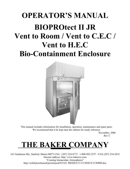
OPERATOR’S <strong>MANUAL</strong><br />
<strong>BIOPROtect</strong> <strong>II</strong> <strong>JR</strong><br />
<strong>Vent</strong> <strong>to</strong> Room / <strong>Vent</strong> <strong>to</strong> C.E.C /<br />
<strong>Vent</strong> <strong>to</strong> H.E.C<br />
Bio-Containment Enclosure<br />
This manual includes information for installation, operation, maintenance and spare parts.<br />
We recommend that it be kept near the cabinet for ready reference.<br />
November, 2006<br />
Rev C<br />
THE BAKER COMPANY<br />
161 Gatehouse Rd., Sanford, Maine 04073 USA ⋅ (207) 324-8773 ⋅ 1-800-992-2537 ⋅ FAX (207) 324-2632<br />
Internet address: http// www.bakerco.com<br />
“Creating Immaculate Atmospheres”<br />
http://solid/prereleased/prereleased/STAN. PRODUCT/313/DOCS/313D000.doc
The <strong>Baker</strong> <strong>Company</strong><br />
INTRODUCTION AND WELCOME<br />
It is a pleasure <strong>to</strong> welcome you <strong>to</strong> the growing number of cus<strong>to</strong>mers who own and operate <strong>Baker</strong><br />
biological safety cabinets. As the inven<strong>to</strong>rs of the laminar flow biological safety cabinet and the leaders in<br />
the field, <strong>Baker</strong> people take special pride in providing a cabinet that is designed for maximum performance.<br />
Your new <strong>BIOPROtect</strong> <strong>II</strong> <strong>JR</strong> cabinet includes many unique features which are included <strong>to</strong> give you<br />
superior performance, simpler maintenance and lower life cycle cost. Your <strong>BIOPROtect</strong> <strong>II</strong> <strong>JR</strong> cabinet is<br />
designed for both safety and value.<br />
In addition <strong>to</strong> the high quality you expect from all <strong>Baker</strong> equipment, this model has been ergonomically<br />
designed <strong>to</strong> provide the lab user with many exciting design features. The revolutionary ergonomic design<br />
will help prevent repetitive motion injury, reduce fatigue and lab accidents and enhance productivity.<br />
You will find your <strong>BIOPROtect</strong> <strong>II</strong> <strong>JR</strong> cabinet suitable for use not only for research and clinical diagnostic<br />
work involving tissue culturing of possibly infectious samples, but also for I.V. drug preparations and other<br />
pharmaceuticals that could have adverse health effects on opera<strong>to</strong>rs and other techniques requiring a<br />
contamination-free atmosphere.<br />
Please note that all open-front containment cabinets, including this one, are for use with low <strong>to</strong> moderate<br />
risk agents only. Open-front cabinets do not provide absolute protection for the user. The adequacy of a<br />
cabinet for user safety should be determined on-site by an industrial hygienist, safety officer or other<br />
qualified person. Remember that you, the owner and user, are ultimately responsible and that you use your<br />
cabinet at your own risk.<br />
We recommend that this manual, along with fac<strong>to</strong>ry test report, be kept near the cabinet for convenient<br />
reference by opera<strong>to</strong>rs and qualified maintenance personnel. If you have any questions about the use or<br />
care of your new <strong>BIOPROtect</strong> <strong>II</strong> <strong>JR</strong> cabinet, please do not hesitate <strong>to</strong> contact our Cus<strong>to</strong>mer Service<br />
Department at 800-992-2537 for assistance or e-mail us at bakerco@bakerco.com.<br />
Sincerely,<br />
Dennis Eagleson<br />
President, CEO<br />
The <strong>Baker</strong> <strong>Company</strong>, Inc.<br />
P.O. Drawer E, Sanford, Maine 04073 (207) 324-8773 1-800-992-2537 FAX (207) 324-3869<br />
Visit our website at www.bakerco.com<br />
http://solid/prereleased/prereleased/STAN. PRODUCT/313/DOCS/313D000.doc
Table of Contents<br />
INTRODUCTION AND WELCOME ................................................................................................ i<br />
Table of Contents................................................................................................................................ii<br />
I - FUNCTION AND DESCRIPTION OF THE <strong>BIOPROtect</strong> <strong>II</strong> <strong>JR</strong> CABINET .............................. 1<br />
Airflow Inside the <strong>BIOPROtect</strong> <strong>II</strong> <strong>JR</strong> Cabinet ............................................................................... 1<br />
Access <strong>to</strong> the Work Area................................................................................................................ 2<br />
Design Details ................................................................................................................................ 3<br />
Performance assurance.............................................................................................................. 3<br />
All-metal plenums..................................................................................................................... 3<br />
Tested HEPA filters .................................................................................................................. 3<br />
Work area lighting .................................................................................................................... 3<br />
Iris Port...................................................................................................................................... 3<br />
Optional Height Adjustable Cart .................................................................................................... 3<br />
Specifications ................................................................................................................................. 4<br />
Dimensions: .............................................................................................................................. 4<br />
Weights ..................................................................................................................................... 4<br />
Utilities: .......................................................................................................................................... 4<br />
Mechanical................................................................................................................................ 4<br />
Electrical ................................................................................................................................... 4<br />
Environmental Conditions.............................................................................................................. 5<br />
Symbols and Terminology ............................................................................................................. 5<br />
<strong>II</strong> - PREPARING THE <strong>BIOPROtect</strong> <strong>II</strong> <strong>JR</strong> CABINET FOR USE ..................................................... 6<br />
The Uses of the <strong>BIOPROtect</strong> <strong>II</strong> Jr.................................................................................................. 6<br />
Location Within the Labora<strong>to</strong>ry ..................................................................................................... 6<br />
Opera<strong>to</strong>r Controls: .......................................................................................................................... 7<br />
1.Blower On / Off Switch – ......................................................................................................7<br />
2.Light On / Off Switch – ......................................................................................................... 7<br />
3.Mute switch - ......................................................................................................................... 7<br />
4 Left Side & Right Side Outlet On / Off –............................................................................... 7<br />
Ground Fault Circuit Interrupter .................................................................................................... 8<br />
Air Pressure Gage......................................................................... Error! Bookmark not defined.<br />
Air Pressure Alarm ......................................................................................................................... 8<br />
Door Operations ............................................................................................................................. 9<br />
To open the viewscreen: ........................................................................................................... 9<br />
http://solid/prereleased/prereleased/STAN. PRODUCT/313/DOCS/313D000.doc
To open the door: ...................................................................................................................... 9<br />
Removing the cart........................................................................................................................... 9<br />
Set-up Procedure .......................................................................................................................... 10<br />
Start-up procedure ........................................................................................................................ 11<br />
Reacting <strong>to</strong> Spills.......................................................................................................................... 12<br />
Decontamination........................................................................................................................... 13<br />
About the HEPA Filters................................................................................................................ 15<br />
IV - ON-SITE CHECKS AND MAINTENANCE PROCEDURES ............................................... 16<br />
Filter Media and Seal Leak Tests ................................................................................................. 16<br />
Procedure for filter leak tests........................................................................................................ 17<br />
The Airflow Balance .................................................................................................................... 18<br />
Airflow Smoke Pattern Test ......................................................................................................... 19<br />
Grounding Continuity Test........................................................................................................... 19<br />
Calibration procedure for Modus Airflow alarm(Digital Differential Pressure Moni<strong>to</strong>r)............ 20<br />
Initial Set Point Settings.......................................................................................................... 20<br />
Low Flow Alarm Setting ........................................................................................................ 20<br />
Check the Calibration ............................................................................................................. 20<br />
Modus Programming Instructions ................................................................................................ 21<br />
1.) Programming the Alarm Set points ................................................................................... 21<br />
2.) Programming the Relay Dead band................................................................................... 21<br />
3.) Returning <strong>to</strong> Normal Operation......................................................................................... 21<br />
Maintenance Notes ....................................................................................................................... 22<br />
Replacing the HEPA Filter........................................................................................................... 22<br />
Changing the Exhaust Filter.................................................................................................... 22<br />
Changing the Supply Filter ..................................................................................................... 23<br />
V. - TROUBLE SHOOTING .......................................................................................................... 24<br />
REPLACEMENT PARTS LIST .................................................................................................. 26<br />
VI. APPENDIX ................................................................................................................................ 27<br />
Modus Installation and Operation Handbook............................................................................... 28<br />
BGA-BIOPROTECT <strong>II</strong>-<strong>JR</strong> <strong>Vent</strong> <strong>to</strong> Room Page 1 ....................................................................... 42<br />
BGA-BIOPROTECT <strong>II</strong>-<strong>JR</strong> <strong>Vent</strong> <strong>to</strong> Room Page 2 ....................................................................... 43<br />
BGA-BIOPROTECT <strong>II</strong>-<strong>JR</strong> <strong>Vent</strong> <strong>to</strong> Room Page 3 ....................................................................... 44<br />
BGA-BIOPROTECT <strong>II</strong>-<strong>JR</strong> Canopy Exhaust Connection(CEC) Page 1 ..................................... 45<br />
http://solid/prereleased/prereleased/STAN. PRODUCT/313/DOCS/313D000.doc
BGA-BIOPROTECT <strong>II</strong>-<strong>JR</strong> Canopy Exhaust Connection(CEC) Page 2 ..................................... 46<br />
BGA-BIOPROTECT <strong>II</strong>-<strong>JR</strong> Canopy Exhaust Connection(CEC) Page 3 ..................................... 47<br />
BGA-BIOPROTECT <strong>II</strong>-<strong>JR</strong> Hard Exhaust Connection(HEC) Page 1.......................................... 48<br />
BGA-BIOPROTECT <strong>II</strong>-<strong>JR</strong> Hard Exhaust Connection(HEC) Page 2.......................................... 49<br />
BGA-BIOPROTECT <strong>II</strong>-<strong>JR</strong> Hard Exhaust Connection(HEC) Page 3.......................................... 50<br />
Wiring Diagram-Standard <strong>BIOPROtect</strong> <strong>JR</strong>.................................................................................. 51<br />
Wiring Diagram – Master <strong>BIOPROtect</strong> <strong>JR</strong> .................................................................................. 53<br />
WARRANTY ................................................................................................................................... 54<br />
TEST REPORT…………………………………………………………………………ATTACHED<br />
http://solid/prereleased/prereleased/STAN. PRODUCT/313/DOCS/313D000.doc
I - FUNCTION AND DESCRIPTION OF THE <strong>BIOPROtect</strong> <strong>II</strong> <strong>JR</strong> CABINET<br />
The <strong>BIOPROtect</strong> <strong>II</strong> <strong>JR</strong> is a Class <strong>II</strong> Bio-Containment Enclosure designed <strong>to</strong> house labora<strong>to</strong>ry robotics or<br />
large apparatus that would not ordinarily fit in a standard Class <strong>II</strong> Biological Safety Cabinet (BSC). Some<br />
important features of the <strong>BIOPROtect</strong> <strong>II</strong> <strong>JR</strong> include, vertical laminar airflow, a front access opening, as well<br />
as supply & exhaust HEPA filters. The unit is designed <strong>to</strong> protect not only the environment and the people<br />
using the cabinet, but also the product within from airborne contaminants. The <strong>BIOPROtect</strong> <strong>II</strong> <strong>JR</strong> can be<br />
configured <strong>to</strong> vent three different ways. <strong>Vent</strong> <strong>to</strong> the room, <strong>Vent</strong> <strong>to</strong> a Canopy Exhaust Connection (C.E.C.)<br />
via a house exhaust system or, <strong>Vent</strong> <strong>to</strong> a Hard Exhaust Connection (H.E.C.) via a house exhaust system.<br />
Although your unit has passed a microbiological test, a modification of NSF/ANSI standard-49-2002e, the<br />
<strong>BIOPROtect</strong> <strong>II</strong> <strong>JR</strong> is not currently listed with the NSF.<br />
Airflow Inside the <strong>BIOPROtect</strong> <strong>II</strong> <strong>JR</strong> Cabinet<br />
Figure 1 shows the name and location of component parts and the typical airflow pattern of the<br />
<strong>BIOPROtect</strong> <strong>II</strong> <strong>JR</strong><br />
The stainless steel metal diffuser (1) just below the supply HEPA (High Efficiency Particulate Air) filter<br />
assures that the work area is bathed in HEPA filtered air. The supply air stream splits so that some is<br />
directed in<strong>to</strong> the front grille (2) and the balance is pulled in<strong>to</strong> the perforated grilles on the rear wall (3). On a<br />
flat table <strong>to</strong>p, in the absence of any obstacles, the air should split roughly in the center of the table.<br />
Because the cabinet must take in air <strong>to</strong> replace the air which is expelled through the exhaust filter, the<br />
same quantity of room air enters the cabinet through the eight inch front access opening. The flow of the<br />
intake air provides the personnel protection (containment) aspect of the cabinet.<br />
The front grille of the cabinet is integral <strong>to</strong> the large hinged door. This door, as well as the side and rear<br />
walls, are maintained under a negative pressure. Air is drawn from the front intake grille, in<strong>to</strong> the hollow<br />
door, and in<strong>to</strong> the right side wall. In this manner the outside air that is drawn in<strong>to</strong> the cabinet as intake is not<br />
allowed <strong>to</strong> penetrate the table <strong>to</strong>p area of the cabinet.<br />
Any and all contaminated air that is captured in the cabinet’s negative pressure plenums (front door, side<br />
walls, rear walls or upper plenum) is pulled in<strong>to</strong> the cabinet’s blower (4). The blower discharges in<strong>to</strong> a steel<br />
box that is a common plenum for the supply and exhaust HEPA filters (5). In this manner, all the air that is<br />
handled by the cabinet is HEPA filtered. The <strong>BIOPROtect</strong> <strong>II</strong> <strong>JR</strong> will exhaust a quantity of air (6) equal <strong>to</strong><br />
that received at the front intake grille. If a leak should occur in a contaminated pressure plenum the negative<br />
pressure will create suction and pull air in, not allowing it <strong>to</strong> escape in<strong>to</strong> the labora<strong>to</strong>ry. If there is a leak<br />
from the positive pressure plenum, the surrounding negative pressure area will recapture the contaminated air<br />
and recirculate it through a HEPA filter.<br />
http://solid/prereleased/prereleased/STAN. PRODUCT/313/DOCS/313D000.doc<br />
Page 1 of 59
Access <strong>to</strong> the Work Area<br />
Figure 1 Typical section with airflow visualization arrows<br />
The <strong>BIOPROtect</strong> <strong>II</strong> <strong>JR</strong> is provided with three modes of access <strong>to</strong> the work area; via the large hinged door<br />
that can be opened <strong>to</strong> access the entire work area, the hinged viewscreen (providing access <strong>to</strong> the work<br />
surface) or from the 8” x 42” access (sash) opening between the bot<strong>to</strong>m of the closed viewscreen and the air<br />
intake grate. The primary means of access must be through the 8” sash opening. This is the only means of<br />
access that will ensure the user protection from contaminants within the enclosure.<br />
The opera<strong>to</strong>r is only protected from airborne particulate when the large front door and the hinged viewscreen<br />
is closed and secured <strong>to</strong> provide an 8” x 42” access (sash) opening<br />
For easy set-up of equipment in the work area, the <strong>BIOPROtect</strong> <strong>II</strong> <strong>JR</strong> has one large door that exposes the<br />
entire work area from floor <strong>to</strong> ceiling <strong>to</strong> an area of 51.5” wide x 68” tall.<br />
http://solid/prereleased/prereleased/STAN. PRODUCT/313/DOCS/313D000.doc<br />
Page 2 of 59
Design Details<br />
Performance assurance<br />
Meticulous care in manufacturing is followed by more than 14 separate performance tests prior <strong>to</strong><br />
shipment of your cabinet. In addition, a complete fac<strong>to</strong>ry test report on the operation of your unit is<br />
included at the rear of this manual.<br />
All-metal plenums<br />
The work area surfaces and plenums of your <strong>BIOPROtect</strong> <strong>II</strong> <strong>JR</strong> have been constructed entirely of<br />
metal in order <strong>to</strong> provide strength, durability, air-tightness and resistance <strong>to</strong> deterioration. External<br />
construction is of 16-gauge cold-rolled steel, protected by a smooth white baked enamel finish.<br />
Tested HEPA filters<br />
Supply and exhaust HEPA filters in the <strong>BIOPROtect</strong> <strong>II</strong> <strong>JR</strong> unit have been found <strong>to</strong> be 99.99 percent<br />
effective on particles of 0.3 micron size. Each filter is scan-tested <strong>to</strong> assure leak-free installation.<br />
Work area lighting<br />
The fluorescent lights are externally mounted within the light canopy <strong>to</strong> minimize heat buildup in the<br />
work area. The unit uses two common F32T8 fluorescent bulbs powered by an efficient and reliable<br />
electronic ballast.<br />
Cable Port<br />
A 2.75” I.D. cable port is provided in each side wall <strong>to</strong> accommodate communications ports from<br />
process equipment without compromising performance.<br />
Optional Height Adjustable Cart<br />
The all stainless steel cart, which is optional on the <strong>BIOPROtect</strong> <strong>II</strong> <strong>JR</strong> was designed <strong>to</strong> accommodate<br />
process equipment weighing no more than 500 Lbs. It’s work surface dimensions are 44” Wide x 34” Deep.<br />
The height of the worksurface can be adjusted by the opera<strong>to</strong>r from 27” <strong>to</strong> 39” by using the manual crank<br />
provided at the front of the cart. For ideal ergonomic performance the cart should be adjusted so that the<br />
work table of the equipment is at the same level as the front intake grille of door on the front of the cabinet.<br />
The cart is provided with swivel casters, all of which are locking. To retract the cart from the work area,<br />
tip the foot operated locking devices at each front caster <strong>to</strong> a horizontal position then pull the cart out of the<br />
work area. To return the cart <strong>to</strong> the cabinet push the cart back in<strong>to</strong> the work area and lock the front casters<br />
by pushing down on the foot operated locking devices. Make certain that the crank handle for the lift system<br />
is facing the front of the cabinet and is retracted under the work table before closing the door.<br />
http://solid/prereleased/prereleased/STAN. PRODUCT/313/DOCS/313D000.doc<br />
Page 3 of 59
Specifications<br />
Dimensions:<br />
Outside: 66” W x 64.44” D x 106.41”H<br />
Usable work area: 51”W x 36.5”D x 75”H (under diffuser)<br />
Cart worksurface: 44”W x 34” D x (27”- 37”) H (height adjusted by opera<strong>to</strong>r).<br />
Weights<br />
Utilities:<br />
Mechanical<br />
Unit weight: The weight of the <strong>BIOPROtect</strong> <strong>II</strong> <strong>JR</strong> cabinet is approximately 1200 lbs.<br />
Cart weight: The weight of the <strong>BIOPROtect</strong> <strong>II</strong> <strong>JR</strong> cart is approximately 250 lbs.<br />
Maximum worksurface capacity: 500 Lbs. uniform load.<br />
Point loads not <strong>to</strong> exceed 125 Lbs. each<br />
Four (4) 3/8” NPT female connections provided for plumbing; all are pre-plumbed <strong>to</strong> the <strong>to</strong>p of the<br />
unit using 3/8” copper tubing. No service fixtures or valves are provided. User must supply fixtures <strong>to</strong><br />
mate with 3/8” NPT female connection on side walls (see general arrangement drawing for details).<br />
Electrical<br />
!!! This cabinet is powered from more than one power source. The cabinet is not electrically safe unless<br />
all power sources are disconnected. Proper Lockout/Tag out procedures should be used !!!<br />
All electrical wiring should comply with the National Electric Code and any applicable Local Electrical<br />
Codes at the site of installation.<br />
The standard <strong>BIOPROtect</strong> <strong>II</strong> Jr has three junction boxes located on the front of the <strong>to</strong>p deck. The<br />
following services need <strong>to</strong> be connected <strong>to</strong> the junction boxes.<br />
One 120Volt, 20Amp, 60 Hz, Single phase connection <strong>to</strong> power the blower. This circuit should be wired<br />
using 12 AWG wire and provided with a 20 Amp circuit breaker that will serve as a disconnect for this<br />
power supply.<br />
One 120 V, 15Amp, 60 Hz, Single phase connection for control power and power <strong>to</strong> the left side wall<br />
duplex. This circuit should be wired using 14 AWG wire and provided with a 15 Amp circuit breaker that<br />
will serve as a disconnect for this power supply.<br />
One 120 V, 15Amp, 60 Hz, Single phase connection for power <strong>to</strong> the right side wall duplex. This circuit<br />
should be wired using 14 AWG wire and provided with a 15 Amp circuit breaker that will serve as a<br />
disconnect for this power supply.<br />
The circuit breakers for these services are <strong>to</strong> be located in close proximity <strong>to</strong> the cabinet.<br />
Other connections may be required for optional equipment.<br />
http://solid/prereleased/prereleased/STAN. PRODUCT/313/DOCS/313D000.doc<br />
Page 4 of 59
The <strong>BIOPROtect</strong> <strong>II</strong> <strong>JR</strong> incorporates a solid-state ‘Stedivolt’ controller <strong>to</strong> adjust the blower mo<strong>to</strong>r<br />
speed. This unit compensates for some variation in incoming line voltage. The usable voltage range is<br />
95 <strong>to</strong> 130V AC. You will need <strong>to</strong> consult the most recent certification test report on the unit <strong>to</strong> determine<br />
what the voltage setting should be for your unit.<br />
Environmental Conditions<br />
The <strong>BIOPROtect</strong> <strong>JR</strong> is designed <strong>to</strong> be used under the following conditions:<br />
Indoor use<br />
Altitudes up <strong>to</strong> 2000 meters<br />
Temperature range from 5° C <strong>to</strong> 40° C<br />
Relative humidity up <strong>to</strong> 80%<br />
Main supply voltage 105 <strong>to</strong> 125 VAC<br />
Maximum relative humidity 80 percent for temperatures up <strong>to</strong> 31°C decreasing linearly <strong>to</strong> 50 percent<br />
relative humidity at 40°C.<br />
Transient over voltages according <strong>to</strong> Installation Category(OVERVOLTAGE CATEGORIES) <strong>II</strong> per UL<br />
61010A-1, Annex J.<br />
Pollution Degree 2<br />
Symbols and Terminology<br />
!<br />
Protective Earth: Any terminal which is intended for connection <strong>to</strong> an external protective<br />
conduc<strong>to</strong>r for protection against electric shock in case of a fault.<br />
General Caution: Refer <strong>to</strong> the instruction manual for information regarding personnel and<br />
environment protection.)<br />
http://solid/prereleased/prereleased/STAN. PRODUCT/313/DOCS/313D000.doc<br />
Page 5 of 59
The Uses of the <strong>BIOPROtect</strong> <strong>II</strong> Jr.<br />
<strong>II</strong> - PREPARING THE <strong>BIOPROtect</strong> <strong>II</strong> <strong>JR</strong> CABINET FOR USE<br />
The <strong>BIOPROtect</strong> <strong>II</strong> <strong>JR</strong> cabinet has been designed <strong>to</strong> provide a work area that protects the experiment<br />
from the environment (Product protection), and protects the users from the experiment (personnel protection<br />
or ‘containment’). The laminar flow biological safety cabinet is designed for work with Biosafety Levels 1,<br />
2 and 3 (low <strong>to</strong> moderate risk) agents as listed in The Center for Disease Control’s “Biosafety in<br />
Microbiological and Biomedical Labora<strong>to</strong>ries”, U.S. Department of Health and Human Services, Public<br />
Health Service, Centers for Disease Control and National Institutes of Health, U.S. Government Printing<br />
Office, Washing<strong>to</strong>n, D.C. 20402. HHS publication number (CDC) 84-8395.<br />
Extremely high risk agents assigned <strong>to</strong> Biosafety level 4 should never be used in this cabinet except in a<br />
certified BSL4 suit room. Please consult your safety professional for a proper risk assessment.<br />
Cautions<br />
* The use of any hazardous material in the cabinet requires that it be moni<strong>to</strong>red by an industrial<br />
hygienist, safety officer or other qualified individual.<br />
* Explosive or flammable substances should never be used in the cabinet unless a qualified safety<br />
professional has evaluated the risk.<br />
* If hazardous biological work is <strong>to</strong> be performed, apply the appropriate biohazard decal which is<br />
enclosed. This is in accord with OSHA regulations, volume 39, number 125, Part <strong>II</strong>.<br />
* If chemical, radiological or other non-microbiological hazards are present, be sure <strong>to</strong> employ<br />
appropriate protective measures in addition <strong>to</strong> formaldehyde decontamination.Also see section 2<br />
“Decon”. Call upon a suitably trained individual <strong>to</strong> moni<strong>to</strong>r the operation.<br />
Location Within the Labora<strong>to</strong>ry<br />
PROPER PLACEMENT WITHIN THE LABORATORY IS ESSENTIAL.<br />
The ideal location for any laminar flow biological safety cabinet is in a dead-end corner of the labora<strong>to</strong>ry<br />
away from personnel traffic, vents, doors, windows or any other sources of disruptive air currents. Published<br />
research from The <strong>Baker</strong> <strong>Company</strong> (see Rake ASM paper, reference #34 in Appendix) and unpublished tests<br />
performed at the National Cancer Institute show that if a draft or other disruptive air current were <strong>to</strong> exceed<br />
the intake velocity of the cabinet, then contamination can enter the work area or escape from it.<br />
http://solid/prereleased/prereleased/STAN. PRODUCT/313/DOCS/313D000.doc<br />
Page 6 of 59
<strong>II</strong>I - PROPER CABINET USE<br />
The <strong>BIOPROtect</strong> <strong>II</strong> Jr. is designed for continuous operation. The <strong>Baker</strong> <strong>Company</strong> recommends<br />
continuous operation <strong>to</strong> keep the interior work space clean and free of unwanted particles. If the blower is<br />
not running, the workspace of the cabinet will become contaminated with room air. If the cabinet’s use is not<br />
unders<strong>to</strong>od or the cabinet is operated incorrectly, it will not provide an adequate protective barrier.<br />
It would be helpful for opera<strong>to</strong>rs <strong>to</strong> learn about the capabilities and limitations of the cabinet by reading<br />
some of the available literature. The Eagleson Institute offers several videotapes and an interactive CD which<br />
illustrate proper operation techniques for biological safety cabinets.<br />
A biological safety cabinet is a valuable supplement <strong>to</strong> good sterile technique, but is not a replacement for<br />
it. All activities that are <strong>to</strong> be performed in your cabinet should first be approved by a competent<br />
professional, such as an industrial hygienist or safety officer. This will ensure the cabinet is appropriate for<br />
the work it will be required <strong>to</strong> do. A competent professional should moni<strong>to</strong>r the cabinet and its operating<br />
personnel at regular intervals <strong>to</strong> see that it is being used correctly.<br />
Opera<strong>to</strong>r Controls:<br />
The opera<strong>to</strong>r controls and indica<strong>to</strong>rs are arranged on the front panel of the unit.<br />
Blower On / Off Switch –<br />
This push but<strong>to</strong>n is a maintained action switch that controls the power <strong>to</strong> the cabinet blower. Pressing<br />
and releasing the push but<strong>to</strong>n from the UP/OFF position will change the switch <strong>to</strong> the DOWN/ON<br />
position. The cabinet blower will start. The GREEN indica<strong>to</strong>r in the push but<strong>to</strong>n will illuminate. Pressing<br />
and releasing the push but<strong>to</strong>n from the DOWN/ON position will change the switch <strong>to</strong> the UP/OFF<br />
position.<br />
Caution: The cabinet audible alarm is disabled when the Blower switch is in the OFF position<br />
Light On / Off Switch –<br />
This pushbut<strong>to</strong>n is a maintained action switch that controls the power <strong>to</strong> the cabinet fluorescent lights.<br />
Pressing and releasing the pushbut<strong>to</strong>n from the UP/OFF position will change the switch <strong>to</strong> the<br />
DOWN/ON position. The cabinet lights will illuminate. The GREEN indica<strong>to</strong>r in the pushbut<strong>to</strong>n will<br />
illuminate. Pressing and releasing the pushbut<strong>to</strong>n from the DOWN/ON position will change the switch <strong>to</strong><br />
the UP/OFF position.<br />
Mute switch -<br />
This pushbut<strong>to</strong>n is a momentary action switch that temporarily mutes the audible alarm. A timer<br />
module inside the canopy controls the length of time that the alarm is muted. This is set at 5 minutes as a<br />
fac<strong>to</strong>ry default but can be changed <strong>to</strong> 1 second <strong>to</strong> 100 hours. It may be desirable <strong>to</strong> increase this setting<br />
when cabinet decontamination is being performed. The YELLOW indica<strong>to</strong>r in the pushbut<strong>to</strong>n will<br />
illuminate while the alarm mute function is active. Should the alarm condition be remedied before the<br />
mute ‘times-out’ the timer will be reset and the mute indica<strong>to</strong>r will not be illuminated.<br />
Left Side & Right Side Outlet On / Off –<br />
A separate 10 amp breaker switch is supplied for the remote switching of power <strong>to</strong> the right and left<br />
outlet receptacle located inside the <strong>BIOPROtect</strong> <strong>II</strong> <strong>JR</strong>. The breaker switches will ‘trip’ if the <strong>to</strong>tal<br />
electrical load on the circuit exceeds 10 amps.<br />
http://solid/prereleased/prereleased/STAN. PRODUCT/313/DOCS/313D000.doc<br />
Page 7 of 59
Ground Fault Circuit Interrupter<br />
Ground fault circuit interrupter (GFCI) outlets are installed on the 115V power circuit on this cabinet.<br />
The GFCI is designed <strong>to</strong> protect the opera<strong>to</strong>r from a possible electrical ground fault hazard. If a<br />
hazardous condition exists the GFCI will cut off electricity <strong>to</strong> the outlet. The but<strong>to</strong>n in the center of the<br />
unit will pop out. If the GFCI “trips” you should first determine and correct the cause of the problem,<br />
then press the but<strong>to</strong>n <strong>to</strong> reset the GFCI.<br />
Air Pressure Alarm<br />
The Air pressure alarm is controlled by a Modus Air Pressure indica<strong>to</strong>r mounted in the control<br />
canopy. Operating & set up instructions for this instrument can be found in the On-Site Checks And<br />
Maintenance section of this manual. When either a High or Low flow condition is present for more than<br />
3 seconds the audible alarm will be activated. Pressing the Mute switch will silence the alarm. The mute<br />
time is determined by the setting of a timer inside the control canopy. Fac<strong>to</strong>ry setting of this timer is 5<br />
minutes. Consult the test report for your cabinet for the fac<strong>to</strong>ry set flow conditions for this alarm. The<br />
<strong>Baker</strong> <strong>Company</strong> recommends continuous operation <strong>to</strong> keep the interior work space clean and free of<br />
unwanted particles.<br />
Caution: The cabinet audible alarm is disabled when the Blower switch is in the OFF position<br />
This feature allows the user <strong>to</strong> turn-off the cabinet blowers when no longer required and the processes<br />
within the cabinet are found <strong>to</strong> be safe <strong>to</strong> personnel and the environment.<br />
Caution: It is recommended that prior <strong>to</strong> turning the Blower OFF you contact your health and safety<br />
officer for decontamination procedures.(also see section 2 “Decon”)<br />
http://solid/prereleased/prereleased/STAN. PRODUCT/313/DOCS/313D000.doc<br />
Page 8 of 59
Door Operations<br />
During cabinet operation, the only access that should be permitted is through the 8” sash opening<br />
provided at the front of the cabinet. For set-up purposes, the viewscreen or the large front door can be opened<br />
<strong>to</strong> provide greater access.<br />
To open the viewscreen:<br />
Caution: Failure <strong>to</strong> latch the viewscreen in the open position may result in injury<br />
Grasp the acrylic panel and pull it away from the door <strong>to</strong> disengage the two grab catches on each side of<br />
the viewscreen.<br />
Swing the panel up <strong>to</strong> engage the support brackets on the cabinet’s <strong>to</strong>p section. You must reach up and<br />
swing the two securing latches down <strong>to</strong> constrain the viewscreen in the open position.<br />
To open the door:<br />
With the viewscreen in the closed position, slide the dead bolt <strong>to</strong> the right <strong>to</strong> disengage the slide from the<br />
door jam. The deadbolt is located just inside the door and mates with a jam located on the left side wall.<br />
Pull the door open. Due <strong>to</strong> the cam rise action of the hinges the door will self close if left open. Swing<br />
the door 100 degrees (slightly more than perpendicular <strong>to</strong> the front of the cabinet) in order <strong>to</strong> override the<br />
self closing feature.<br />
Removing the cart<br />
Caution: It is recommended that prior <strong>to</strong> cart removal you contact your health and safety<br />
officer for decontamination procedures. (also see section 2 “Decon”)<br />
Should it be necessary <strong>to</strong> remove the cart, you must open the front door <strong>to</strong> fully expose the <strong>BIOPROtect</strong> <strong>II</strong><br />
<strong>JR</strong>’s interior work bay. This area is assumed <strong>to</strong> have contamination so use caution in the way you approach<br />
the task.<br />
• Decontaminate and clean the unit as recommended by your health and safety officer.<br />
• Open the door <strong>to</strong> expose the cabinet’s work bay.<br />
• Any equipment on the cart should be disconnected from the side wall service connections and<br />
removed from the cable ports.<br />
• Unlock the front casters by pulling up the foot operated locking devices. When the locking device is<br />
in a horizontal position it is unlocked.<br />
• Use the hand crank <strong>to</strong> lower the height of the work surface if necessary. Check that your equipment<br />
will clear the front header if it is allowed <strong>to</strong> be left on the cart.<br />
• Pull the cart out and away from the <strong>BIOPROtect</strong> <strong>II</strong> <strong>JR</strong>.<br />
http://solid/prereleased/prereleased/STAN. PRODUCT/313/DOCS/313D000.doc<br />
Page 9 of 59
Set-up Procedure<br />
This section outlines the tasks required <strong>to</strong> properly install au<strong>to</strong>mated labora<strong>to</strong>ry work stations within<br />
the <strong>BIOPROtect</strong> <strong>II</strong> <strong>JR</strong>. This does not replace the recommendations of the equipment manufacturer. It is<br />
assumed that the user is familiar with the set-up and operation of the ancillary equipment.<br />
• Place the equipment on the cart’s table <strong>to</strong>p so that the equipment is within the area of the table <strong>to</strong>p as<br />
defined by the four corners. The front of the equipment must face the front of the cart (crank handle<br />
side).<br />
• Using the crank handle provided on the cart, adjust the cart’s height until the work table of the<br />
equipment is flush or below the intake grill section of the door. S<strong>to</strong>w the crank handle under the work<br />
table.<br />
• Make utility connections <strong>to</strong> the side wall services.<br />
• Close the front door of the <strong>BIOPROtect</strong> <strong>II</strong> <strong>JR</strong> and make certain that you can perform any manual<br />
operations on the equipment through the 8” x 42” sash opening provided.<br />
• Make certain that no part of the equipment blocks or hangs over the front intake grilles.<br />
• Power and run all equipment. Make certain that the equipment and cabinet is operating properly and<br />
that none of the <strong>BIOPROtect</strong> <strong>II</strong> <strong>JR</strong>’s circuit breakers have ‘tripped’.<br />
• Have a certifier or safety officer witness the air currents (using a smoke tracer) <strong>to</strong> determine that the<br />
equipment does not compromise the cabinet’s ability <strong>to</strong> provide personnel and product protection.<br />
The user may choose <strong>to</strong> use a particle counter <strong>to</strong> evaluate the product protection capacity of the<br />
cabinet. A measurement of the personnel protection capacity of the cabinet (containment), should the<br />
user deem it necessary, will be a more involved test and will require a third party skilled in the<br />
operation of the BIO-analog test or the KI-discus test.<br />
http://solid/prereleased/prereleased/STAN. PRODUCT/313/DOCS/313D000.doc<br />
Page 10 of 59
Start-up procedure<br />
• If the unit has not been left running continuously, press the blower on/off switch. The switch will be<br />
illuminated when switched on. The cabinet’s audible alarm may activate for several seconds until the<br />
blower has come up <strong>to</strong> full speed. Make sure that you have cabinet airflow, either by listening for<br />
blower sound or feeling the airflow across your fingers. Check the reading on the air pressure gauge.<br />
The reading on the gauge should be consistent with the last time the unit was on.<br />
• Turn on the fluorescent light. The switch will become illuminated in the ‘on’ position and the<br />
fluorescent bulbs should activate.<br />
• Wipe down the interior area of the cabinet with a surface disinfectant.<br />
•<br />
• NOTES:<br />
• Some disinfectants may corrode or stain the steel surfaces. If this happens, clean the<br />
• surfaces afterward with a disinfectant-detergent and rinse with sterile tap water <strong>to</strong> prevent corrosion<br />
• Blocking the front and rear perforated grills must be avoided. If wipes or absorbent<br />
• <strong>to</strong>wels are used on the work surface, be sure <strong>to</strong> keep them away from the grills.<br />
• Check that the position of the rear wall dampers (two upper and two lower) are consistent with the<br />
settings from the fac<strong>to</strong>ry test report.<br />
• After your equipment is in place inside the cabinet, close and secure the door. All operations inside<br />
the <strong>BIOPROtect</strong> <strong>II</strong> <strong>JR</strong> must be carried out through the unit’s 8” sash opening.<br />
•<br />
Caution: The <strong>BIOPROtect</strong> <strong>II</strong> <strong>JR</strong> will not provide adequate personnel protection unless the front door and<br />
viewscreen are closed.<br />
•<br />
• After a procedure has been completed, all equipment which has been in contact with the research<br />
agent should be enclosed, and the entire surface decontaminated. Trays of discarded items should be<br />
covered. The cabinet should then be allowed <strong>to</strong> run for at least three minutes with no activity so that<br />
the airborne contaminant will be purged from the work area.<br />
• After you have removed all materials, culture apparatus, etc., decontamination of the interior surfaces<br />
should be repeated. Check the work area carefully for spilled or splashed nutrient which might<br />
support bacterial growth. And never use the cabinet <strong>to</strong> s<strong>to</strong>re supplies or labora<strong>to</strong>ry equipment.<br />
http://solid/prereleased/prereleased/STAN. PRODUCT/313/DOCS/313D000.doc<br />
Page 11 of 59
Reacting <strong>to</strong> Spills<br />
Caution: An Emergency spill containment and clean-up procedure should be established<br />
prior <strong>to</strong> an accident<br />
Spilled fluid on the floor of the <strong>BIOPROtect</strong> <strong>II</strong> <strong>JR</strong> is contained within the stainless steel work area of the<br />
cabinet via the threshold placed under the unit’s door. The threshold will contain a volume of approximately<br />
1 gallon (3 liters) of fluid. However, because the <strong>BIOPROtect</strong> <strong>II</strong> <strong>JR</strong> cabinet bears directly on the users floor<br />
there is no drain provided.<br />
• It is recommended that the researchers, in coordination with their consulting safety professional, have<br />
a written plan available in case of an accidental exposure or spill.<br />
• In the case of biological spill, for example, the area containing the spill may be flooded with an<br />
appropriate disinfectant. After the disinfectant has had time for a complete kill, remove the residue. If<br />
you have used a disinfectant which is harmful <strong>to</strong> stainless steel (Hypochlorite bleach solutions, for<br />
example) be sure that none remains <strong>to</strong> corrode cabinet surfaces.<br />
Clean the surfaces with sterile water.<br />
• The Center for Disease Control has published “Biosafety in Microbiological and Biomedical<br />
Labora<strong>to</strong>ries.” If you have a spill involving a hazardous Biosafety Level 2 or 3 agent, then you are<br />
advised <strong>to</strong> leave the cabinet running so as <strong>to</strong> let the aerosols settle before you start cleanup<br />
procedures. With some spills, it may be necessary <strong>to</strong> decontaminate the room with an agent such as<br />
formaldehyde gas. (Biosafety Level 4 agents should never be used in the type of cabinet.)<br />
• If the spill contains volatile liquids which generate vapors creating a danger of fire or explosion, turn<br />
off the unit and other electrical equipment. Evacuate and seal the room and call for immediate help<br />
from a safety professional.<br />
• If the agent is a hazardous chemical, it may be recommended that a Spill Kit be kept readily<br />
available. This kit should be clearly labeled, and might include such items as a respira<strong>to</strong>r, chemical<br />
splash goggles, two pairs of gloves, two sheets of absorbent material, spill control pillows, a solution<br />
<strong>to</strong> clean the contaminant, and waste disposal bags or other containers. Consult your safety<br />
professional for proper procedures and treatment of the specific agents you plan <strong>to</strong> use.<br />
http://solid/prereleased/prereleased/STAN. PRODUCT/313/DOCS/313D000.doc<br />
Page 12 of 59
Decontamination<br />
Whenever maintenance, service or repairs are needed in a contaminated area of your cabinet, the unit<br />
must first be decontaminated by an appropriate agent. The National Institute of Health, National Cancer<br />
Institute and the Center for Disease Control have all recommended the use of formaldehyde gas for most<br />
microbiological agents. Its application requires individuals who are experienced in the decontamination of<br />
cabinets, since the gas itself is <strong>to</strong>xic. Consult the NSF/ ANSI-standard-49-2002 Annex G. “Recommended<br />
Microbiological Decontamination Procedure”, contact NSF International, 789 North Dixboro Road,<br />
P.O. Box 130140, Ann Arbor Michigan 48113-0140.<br />
Whatever gas you choose, have the proper safety equipment (gas masks, protective clothing, etc.) within<br />
easy reach. In addition, you will want <strong>to</strong> be sure that the gas you are using will be effective against all of the<br />
biological agents within the cabinet. When you have decided which gas <strong>to</strong> use, post the antidote <strong>to</strong> it in a<br />
visible and nearby location. The volume of the <strong>BIOPROtect</strong> <strong>II</strong> <strong>JR</strong> cabinet is approximately 75 cubic feet, this<br />
will help you determine the required amount of decontaminating gas.<br />
Carcinogens present a unique chemical deactivation problem and the standard biological decontamination<br />
will not be effective against chemicals or other non-biologic materials. With materials of this kind, consult a<br />
qualified safety professional.<br />
Decontamination procedure<br />
Warning! This procedure should be performed by qualified technicians only.<br />
Surface-disinfect the inside of the window and all other surfaces on the view screen assembly.<br />
Multiply the <strong>to</strong>tal volume of the cabinet (75 ft 3 ) by .3 gram/ft 3 ) <strong>to</strong> determine the amount of<br />
paraformaldehyde required <strong>to</strong> decontaminate the cabinet. If the cabinet is vented <strong>to</strong> the outside you must<br />
consider the volume of the duct work in the paraformaldehyde calculation.<br />
Prior <strong>to</strong> sealing up the cabinet make sure all gas or flammable petcocks are closed and pressure tight.<br />
The inside cabinet work space must be at room temperature with 60% <strong>to</strong> 85% relative humidity. If relative<br />
humidity is low (below 60%) add boiling water in the work space. Moni<strong>to</strong>r the inside of the cabinet with a<br />
humidity meter. Relatively humidity above 85% will require extra clean up which will be covered in step 15.<br />
Note:<br />
Without the proper relative humidity the formaldehyde gas will not be effective. The mode of entry of<br />
formaldehyde in<strong>to</strong> the living organisms is through the cell wall by the absorption of water.<br />
Place a heating mantle with paraformaldehyde in the work space. The heating mantle must be able <strong>to</strong> reach<br />
450 degrees F and must have a grounded plug which should be plugged in <strong>to</strong> an outlet outside the cabinet.<br />
Place a second heating mantle in the cabinet with 60% more by weight of ammonium bicarbonate and 10%<br />
more if using ammonium carbonate, than paraformaldehyde. This will be used later in step 13 <strong>to</strong> neutralize<br />
the formaldehyde gas.<br />
This step is recommended. Place spore strips inside the cabinet <strong>to</strong> confirm the decontamination process has<br />
been successful.<br />
If the cabinet is vented <strong>to</strong> the room, use a sheet of plastic and seal the front access and exhaust port openings.<br />
These openings should be sealed such that the exhaust airflow recirculates back <strong>to</strong> the front access opening.<br />
This will promote the even distribution of formaldehyde gas throughout the cabinet.<br />
If the cabinet is vented <strong>to</strong> the outside, then the exhaust transition should have a means <strong>to</strong> recirculate the<br />
exhaust airflow back <strong>to</strong> the cabinet blower if possible. This will promote the even distribution of<br />
formaldehyde gas through the exhaust filter. Seal the front access opening.<br />
Turn on the heating mantle containing the paraformaldehyde flakes.<br />
http://solid/prereleased/prereleased/STAN. PRODUCT/313/DOCS/313D000.doc<br />
Page 13 of 59
After 25% of the paraformaldehyde has depolymerized, turn on the cabinet blower for 10 <strong>to</strong> 15 seconds.<br />
Repeat after 50%, 75% and 100% of the paraformaldehyde has depolymerized, approx. 20 <strong>to</strong> 30 mins..<br />
Allow the formaldehyde gas a minimum residence time of 6 hours, preferably over night.<br />
Turn on the heating mantle containing ammonium bicarbonate (NH4HCO3). After 25% of the ammonium<br />
bicarbonate has depolymerized turn on the cabinet blower for 10 <strong>to</strong> 15 seconds. Repeat after 50%, 75% and<br />
100% of the chemical has depolymerized <strong>to</strong> neutralize the formaldehyde. Turn on the cabinet blower and<br />
allow the two gases <strong>to</strong> circulate for at least one hour.<br />
Check for formaldehyde by using a gas sampling device (dregger tube) <strong>to</strong> be sure the formaldehyde is at a<br />
safe level inside the lab space.<br />
Cut open the plastic and vent the cabinet <strong>to</strong> the outside.<br />
Aseptically remove spore strip and place in Trypticase-soy broth and incubate for 7 days. No growth will<br />
verify the decontamination process.<br />
When cleaning up, you may find residual paraformaldehyde (white powder) on the metal or glass surfaces.<br />
To remove this, use ammonia in warm water, wear gloves and wipe down the affected surfaces. The<br />
paraformaldehyde will dissolve in water and be neutralized by the ammonia.<br />
•<br />
http://solid/prereleased/prereleased/STAN. PRODUCT/313/DOCS/313D000.doc<br />
Page 14 of 59
About the HEPA Filters<br />
The HEPA filter is one of the essential components of a biological safety cabinet. It is the shield which<br />
stands between the environment and the experimental agent. Some questions that the user should ask<br />
regarding the use of chemical agents in the <strong>BIOPROtect</strong> <strong>II</strong> <strong>JR</strong> are as follows:<br />
• Are these chemicals, either singly or in combination, able <strong>to</strong> attack filter components?<br />
• Are these chemicals potentially <strong>to</strong>xic <strong>to</strong> the opera<strong>to</strong>r? Is there any combination of two or more which<br />
could be <strong>to</strong>xic? If the cabinet is being correctly used and only the opera<strong>to</strong>r’s hands and arms are<br />
inside the machine, then <strong>to</strong>xicity or irritation could occur through skin penetration. A proper<br />
evaluation of <strong>to</strong>xicity must deal not only with onetime exposure, but also with the effect of many<br />
small exposures over a period of time.<br />
• Are these chemicals explosive or flammable? If so, they should never be used in your cabinet. With<br />
a buildup caused by recirculation of air, an explosion can be the result of a mo<strong>to</strong>r spark or a burner<br />
operation in the work area.<br />
• In cases where chemical carcinogens, mutagens or tera<strong>to</strong>gens are <strong>to</strong> be used, the risks should be<br />
carefully weighed in choosing a cabinet. Where the exhaust effluent contains a contaminant, it may<br />
need treatment.<br />
• The life of a filter is determined by how it is used and how often. Under normal labora<strong>to</strong>ry<br />
conditions, you can expect up <strong>to</strong> five years of use. However, misuse or a heavy dust load within the<br />
cabinet will shorten any filter’s lifetime. Bunsen burners and misuse of chemicals will also shorten<br />
the useful life.<br />
http://solid/prereleased/prereleased/STAN. PRODUCT/313/DOCS/313D000.doc<br />
Page 15 of 59
IV - ON-SITE CHECKS AND MAINTENANCE PROCEDURES<br />
We recommend that the filter leak checks be performed before initial use, after relocation and after each<br />
filter change. They should also be carried out at regular intervals, usually six months or one year, as<br />
specified by an industrial hygienist, safety officer or other qualified person.<br />
As reported earlier in this manual, each individual cabinet made by The <strong>Baker</strong> <strong>Company</strong> is carefully<br />
tested before it leaves the fac<strong>to</strong>ry. Your copy of the test report, which you will find at the back of this<br />
manual, gives the fac<strong>to</strong>ry test results for your <strong>BIOPROtect</strong> <strong>II</strong> <strong>JR</strong> cabinet.<br />
Use it as your record of the original testing, and as your guide <strong>to</strong> testing in the future. To gain many years<br />
of satisfac<strong>to</strong>ry service; please be sure that your maintenance personnel come as close as possible <strong>to</strong><br />
duplicating these original test figures. Your test procedures should be identical <strong>to</strong> ours so that comparing test<br />
results will have meaning. Please correspond directly with us <strong>to</strong> request detailed procedures for your<br />
particular cabinet model.<br />
Filter Media and Seal Leak Tests<br />
When preparing your cabinet for use after shipment, and then at prescribed intervals throughout its<br />
working life, you will need <strong>to</strong> verify that the filters have maintained their integrity. This is done by scan<br />
testing the filter faces and seals. The Institute of Environmental Sciences recommended practice IES-RP-<br />
CC034.1 would be a good reference for this testing.<br />
The equipment needed will be:<br />
• An aerosol pho<strong>to</strong>meter. The instrument should sample air at a flow rate of 1 CFM.<br />
• A (D.O.P) genera<strong>to</strong>r with Laskin nozzle(s). Liquid dioctylphthalate (DOP), dioctylsebacate or<br />
comparable substance aerosolized by flowing air through the nozzle(s). When generated with<br />
Laskin type nozzle(s), the mean droplet size of the aerosol is 0.1 –3.0 micron with an average of<br />
0.45 micron.<br />
http://solid/prereleased/prereleased/STAN. PRODUCT/313/DOCS/313D000.doc<br />
Page 16 of 59
Procedure for filter leak tests<br />
• Decontaminate the cabinet in accordance with NSF/ANSI standard-49-2002 and your health and<br />
safety officer.<br />
• Remove the front upper panel by first removing the ¼-20 hardware. Remove the damper from the<br />
front of the filter. This will expose the exhaust filter.<br />
• Find the 1/8” NPT hose barb on the <strong>to</strong>p of the cabinet used for measuring the upstream concentration<br />
of challenge.<br />
• Turn on the aerosol pho<strong>to</strong>meter and set-up according <strong>to</strong> the manufacturer's instructions.<br />
• With the cabinet’s blower running, position the D.O.P. genera<strong>to</strong>r so as <strong>to</strong> introduce air generated<br />
smoke in<strong>to</strong> any of the work bay openings (side wall <strong>to</strong> door openings or rear wall openings are all<br />
appropriate for introducing challenge). Measure the upstream concentration of the challenge. You<br />
must have a concentration of at lease 10 micrograms per liter.<br />
• Supply Filter: Remove the diffuser prior <strong>to</strong> scanning the filter. Holding the pho<strong>to</strong>meter probe no more<br />
than one inch from the filter face scan the entire surface area and perimeter (filter gasket frame area)<br />
in slightly overlapping strokes at a traverse rate of not more than ten feet per minute.<br />
• Exhaust filter: You may scan the downstream face of the exhaust filter from outside of the cabinet.<br />
• Eliminate leaks in the gasket frame area by re-tightening the filter gasket.<br />
• An unacceptable leak is defined as a reading greater than 0.01%<br />
http://solid/prereleased/prereleased/STAN. PRODUCT/313/DOCS/313D000.doc<br />
Page 17 of 59
The Airflow Balance<br />
Warning!<br />
This procedure should be performed by qualified technicians only.<br />
The airflow balance which is set at the fac<strong>to</strong>ry provides your unit with the air volume and velocity control<br />
<strong>to</strong> minimize leakage or airborne contamination either in or out of the work area.<br />
In order <strong>to</strong> duplicate as closely as possible the airflow characteristics described in the original fac<strong>to</strong>ry test<br />
report, please follow these steps:<br />
1. Make certain that the front door and viewscreen are closed and secured so as <strong>to</strong> make an 8” x 42”<br />
horizontal access opening.<br />
2. Using a DIM (Direct Intake Measurement) measure the flow rate in<strong>to</strong> the front access opening. Take at<br />
least five (5) consecutive readings. Average the readings and divide by 2.3 square feet (area of the front<br />
access opening). Acceptable range of the average shall be 100-110 FPM.<br />
3. Using a hot wire anemometer mounted on a ring stand within the work area, take readings with the<br />
anemometer probe set 6” below the diffuser. The location of these readings should be the same as shown in<br />
the fac<strong>to</strong>ry test report. The average of these velocity readings must be in the range between 50 and 70 FPM.<br />
4. After you have compared your figures with those originally taken at the fac<strong>to</strong>ry, make whatever<br />
adjustments are necessary. Use the mo<strong>to</strong>r speed control and the exhaust damper <strong>to</strong> bring the intake and<br />
downflow average values within the specifications.<br />
5. As the HEPA filters load up with particulates, airflow will be maintained au<strong>to</strong>matically <strong>to</strong> some extent.<br />
When the air flow is diminished you will have <strong>to</strong> increase the mo<strong>to</strong>r speed <strong>to</strong> maintain the specified intake<br />
and downflow velocity averages. This is done via the speed controller located in the light canopy.<br />
Warning!<br />
When the light canopy is lowered, some electrical parts are exposed. Do not perform this work unless<br />
you are a trained electrician or electronic technician.<br />
!!!!Note that terminals M1 & M2 as well as L1 & L2 are high Voltage.!!!!<br />
On the speed controller, turn the potentiometer clockwise until you have the desired airflow. Use a<br />
voltmeter <strong>to</strong> check the voltage across terminals M1 & M2. This is the voltage out <strong>to</strong> the mo<strong>to</strong>r. If the airflow<br />
cannot be maintained, it will necessary <strong>to</strong> replace the HEPA filters.<br />
(See “Procedure for HEPA Filter Replacement” later in this section.).<br />
http://solid/prereleased/prereleased/STAN. PRODUCT/313/DOCS/313D000.doc<br />
Page 18 of 59
Airflow Smoke Pattern Test<br />
Airflow smoke patterns have been shown <strong>to</strong> vary depending on the equipment that is used inside the<br />
cabinet. The <strong>BIOPROtect</strong> <strong>II</strong> <strong>JR</strong> has been tested with the cart only. A description of this testing is<br />
summarized in the test report. However, when the <strong>BIOPROtect</strong> <strong>II</strong> <strong>JR</strong> is set-up properly (i.e. your set-up<br />
should not block or restrict the grilles and diffusers provided) the appearance of the airflow directly at the 8”<br />
access openings must be consistent with that described in the test report.<br />
To check for the direction of air movement, use a smoke genera<strong>to</strong>r and trace along the front access<br />
opening on the inside of the cabinet. Observe that no smoke is escaping from the work area.<br />
In order <strong>to</strong> be sure that room air is not entering the work area, trace along the outside of the front access<br />
opening. Observe that no smoke penetrates <strong>to</strong> the work surface.<br />
Grounding Continuity Test<br />
Using an Ohmmeter, set it <strong>to</strong> read the low resistance scale. Touch the two leads <strong>to</strong>gether and see that the<br />
display reads 0.1Ω <strong>to</strong> 0.0Ω. Touch one lead <strong>to</strong> the ground lug on the cabinet power cord while <strong>to</strong>uching the<br />
other lead <strong>to</strong> bare metal on the unit where the user would be likely <strong>to</strong> <strong>to</strong>uch the cabinet. According <strong>to</strong> NSF/<br />
ANCI-standard 49-2202 the maximum allowable shall be 0.15Ω (Max allowable for UL is 0.50Ω ).<br />
http://solid/prereleased/prereleased/STAN. PRODUCT/313/DOCS/313D000.doc<br />
Page 19 of 59
Calibration procedure for Modus Airflow alarm(Digital Differential Pressure Moni<strong>to</strong>r).<br />
Note: This procedure MUST be followed every time the damper width has been changed.<br />
Initial Set Point Settings<br />
Balance the cabinet air flows <strong>to</strong> nominal operating set point per manufacturer instruction.( See<br />
instruction label on front of cabinet).<br />
Record voltage <strong>to</strong> mo<strong>to</strong>r/blower (M1, M2 on speed control) and measure and record damper/ slot<br />
width<br />
Make certain that the Modus displays 0.000 when zero pressure is applied(This can be easily<br />
accomplished by removing the Tygon tubing from the hose barb fitting). Use the “zero” function if<br />
necessary.<br />
Re-connect the tygon tubing and make sure that the value displayed is negative(-) when the cabinet is<br />
running.<br />
Low Flow Alarm Setting<br />
Place a DIM airflow hood on the front of the cabinet or use the 3 inch method for measuring inflow.<br />
Adjust cabinet <strong>to</strong> a 20% reduction in airflow by decreasing the voltage <strong>to</strong> mo<strong>to</strong>r. DO NOT adjust the<br />
damper<br />
Record the exhaust/ damper pressure on Modus (indication of exhaust plenum pressure at<br />
20% reduction) and voltage <strong>to</strong> mo<strong>to</strong>r/ blower (across M1, M2 on speed control)<br />
Set the Modus High Alarm set point <strong>to</strong> the 20% reduction in pressure recorded in step 14 (per Modus<br />
programming instructions below)<br />
Set the Modus dead band <strong>to</strong> .002 (per Modus programming instructions below).<br />
Return cabinet <strong>to</strong> Nominal Set Point voltage, recorded in step 2<br />
Check the Calibration<br />
Set Point Check<br />
While measuring the intake airflow with a DIM, reduce the airflow by decreasing the voltage <strong>to</strong><br />
mo<strong>to</strong>r/ blower until a 20% reduction in flow is measured. Check that the low set point alarms at this<br />
value. If not, reset Modus low alarm set point <strong>to</strong> alarm as desired, per instructions. Return cabinet<br />
<strong>to</strong> Set Point Voltage.<br />
http://solid/prereleased/prereleased/STAN. PRODUCT/313/DOCS/313D000.doc<br />
Page 20 of 59
Modus Programming Instructions<br />
1.) Programming the Alarm Set points<br />
After the first press of MODE, the HI LED flashes, indicating the HI set point is being entered. Press<br />
the ARROW key repeatedly <strong>to</strong> display the desired digit. Next, press the MODE <strong>to</strong> move <strong>to</strong>wards the<br />
most significant digit, and repeatedly press the ARROW key <strong>to</strong> advance the digit’s value. Continue<br />
for the remaining digits. The sign of the set point (+ or -) is selected last.<br />
After the HI set point has been programmed, press the MODE <strong>to</strong> enter the LO set point. The LO<br />
alarm LED flashes, and you can repeat the above process <strong>to</strong> program the LO set point.<br />
2.) Programming the Relay Dead band<br />
The dead band selection is provided <strong>to</strong> keep the relays from chattering when the pressure varies near<br />
the set point. To display the dead band, press MODE once after setting the LO set point polarity in<br />
the previous step. Both alarm LEDs flash. The three digits displayed are the dead band width, in the<br />
same units used for data display. Press the ARROW and MODE keys as described earlier <strong>to</strong> step the<br />
dead band <strong>to</strong> a value of .002.<br />
3.) Returning <strong>to</strong> Normal Operation<br />
Press MODE once after the setting the dead band parameters. The digit “1” on the left indicates the<br />
unit is in analog setting mode. Since there are no analog outputs, the mode key can be pressed a final<br />
time <strong>to</strong> end programming and return <strong>to</strong> the normal pressure display.<br />
http://solid/prereleased/prereleased/STAN. PRODUCT/313/DOCS/313D000.doc<br />
Page 21 of 59
Maintenance Notes<br />
Replacing the HEPA Filter<br />
WARNING!<br />
Before any panels are removed, the cabinet must be decontaminated. The filters are sure <strong>to</strong> have<br />
collected microorganisms and other potentially harmful particles generated from the work area during<br />
their lifespan. Maintenance personnel should not allow themselves <strong>to</strong> be exposed.<br />
It should also be remembered that a specific gaseous decontaminant may work against<br />
microorganisms, but not against chemical agents. Where chemical agents are present, consult an<br />
industrial hygienist or other qualified person(s).<br />
If the differential pressure moni<strong>to</strong>r presents an alarm, or if your periodic checks of <strong>to</strong>tal airflow show a<br />
drop of more than 5% of the nominal set point, the filters may be loading with particulates. As explained<br />
earlier in this section, the blower speed can be manually increased <strong>to</strong> compensate for filter loading.<br />
However, when the airflow can no longer be maintained or when the filters are damaged, they need <strong>to</strong> be<br />
replaced.<br />
A contaminated filter must be handled with caution. Personnel should be protected by clothing or<br />
breathing apparatus as necessary <strong>to</strong> the nature of the hazard. It is advisable <strong>to</strong> seal the contaminated side of<br />
the filter by taping a plastic sheet or cardboard over the face before removal. This should minimize the<br />
number of particles shaken loose from the filter. Once removed, the filter should immediately be sealed in a<br />
biological hazard bag and then disposed of safely in accordance with environmental regulations.<br />
After filter replacement has been completed, the cabinet and the room should be cleaned and<br />
decontaminated in a manner consistent with the nature of the hazardous material. The cleaning materials,<br />
along with the protective gear and clothing, should be properly disposed of.<br />
HEPA filters are very easily damaged, and you will want <strong>to</strong> use great care during handling so as <strong>to</strong> avoid<br />
injury <strong>to</strong> the filter media and gasket surface. When installing the new filters, it is a good idea <strong>to</strong> tape a piece<br />
of cardboard over the filter media <strong>to</strong> give protection against dropped wrenches or misdirected fingers. Of<br />
course, you will need <strong>to</strong> make sure that the cardboard is removed before the access panels are re-installed.<br />
Inspect the filters carefully before and after installation. A broken or damaged filter is worthless.<br />
Changing the Exhaust Filter<br />
The <strong>BIOPROtect</strong> <strong>II</strong> <strong>JR</strong> requires one exhaust filter measuring 19” x 38” x 12” deep (consult test report<br />
for part numbers and specifications). This filter is arranged <strong>to</strong> face the front of the unit so as <strong>to</strong> eliminate<br />
the nuisance of ceiling restrictions on the exhaust air.<br />
To service the exhaust filter remove the panel from the front of the unit using a 3/8” nut driver or<br />
socket <strong>to</strong> remove the ¼-20 hardware. Using the same 3/8” driver, remove the hardware from the filter<br />
securing frame. Pull the frame and filter away from the unit.<br />
Prepare the new filter by putting a light coat of silicone grease on the face of the gasket. Clean the<br />
sealing flange thoroughly. Then carefully slide the new filter in<strong>to</strong> place and make sure that it is properly<br />
seated on the flange. Replace the filter clamp assembly and perform the leak test described earlier in this<br />
chapter.<br />
http://solid/prereleased/prereleased/STAN. PRODUCT/313/DOCS/313D000.doc<br />
Page 22 of 59
Changing the Supply Filter<br />
The <strong>BIOPROtect</strong> <strong>II</strong> <strong>JR</strong> requires one supply filter measuring 32” x 45” x 3” deep (consult test report<br />
for part numbers and specifications). This filter is arranged so as <strong>to</strong> be serviced from inside the<br />
<strong>BIOPROtect</strong> <strong>II</strong> <strong>JR</strong>’s work area. Consequently you will have <strong>to</strong> remove the cart and any equipment from<br />
inside the cabinet prior <strong>to</strong> changing the filters.<br />
To service the supply filter first swing the diffuser down allowing it <strong>to</strong> rest on the rear wall by<br />
removing the ¼-20 screws at the front edge of the diffuser panel. Next using a 3/8” driver remove the ¼-<br />
20 hardware that secures the frame <strong>to</strong> the filter. This frame supports the filter.<br />
Prepare the new filter by putting a light coat of silicone grease on the face of the gasket. Clean the<br />
sealing flange thoroughly. Place the new filter in the center of the frame and install the frame in<strong>to</strong> the<br />
cabinet using the ¼-20 hardware. Conduct a filter leak check as described in the earlier chapter.<br />
http://solid/prereleased/prereleased/STAN. PRODUCT/313/DOCS/313D000.doc<br />
Page 23 of 59
V. - TROUBLE SHOOTING<br />
Here are some suggestions based on our experience with the use and misuse of biological safety<br />
cabinets.<br />
CAUTION:<br />
Whenever the potentially contaminated areas of your cabinet must be entered, make sure that the unit is<br />
first decontaminated by use of an appropriate method by qualified personnel.<br />
When a smoke test indicates that there is air flowing from the interior of your cabinet in<strong>to</strong> the<br />
surrounding room:<br />
• Make certain that the front door is closed and the front intake grilles are not blocked. This will create<br />
an 8” x 42” horizontal opening in the front of the cabinet.<br />
• If your cabinet is connected <strong>to</strong> an in-house exhaust, make sure that there is adequate exhaust suction<br />
and no back pressure. Also, be sure the dampers are open. Re-balance the exhaust system <strong>to</strong> handle<br />
an adequate quantity of air and static pressure (suction). Consult with building maintenance people.<br />
• The exhaust filter may be loaded with dirt if the unit has been in service for some time.<br />
Decontaminate, and replace the HEPA filter.<br />
• There may be high cross-drafts in the room which are causing the outflow of smoke. Check the<br />
airflow balance, following the procedure recommended in an earlier section of this chapter. Eliminate<br />
the source of the cross-draft.<br />
If there is no airflow within the work area:<br />
• Make sure that the blower switch is turned on. The indica<strong>to</strong>r on the pushbut<strong>to</strong>n should be<br />
illuminated.<br />
• If the lights are working, then turn the blower switch off and let the cabinet rest for ten minutes.<br />
When the time has passed, turn the blower switch on again. If the blower starts, you know there has<br />
been overheating of the blower mo<strong>to</strong>r. Also check the wiring connections inside of the light canopy<br />
which connects the canopy <strong>to</strong> the cabinet. Be sure the connections are pushed <strong>to</strong>gether.<br />
• If these solutions do not correct the problem, or if the blower failed <strong>to</strong> start after the rest period, then<br />
either the speed control, blower mo<strong>to</strong>r or capaci<strong>to</strong>r is defective. A qualified electrician can find out if<br />
the speed control is defective by bypassing it, using the wiring diagram in the Appendix of this<br />
manual as a guide. If there is a noise problem, it may be caused by mo<strong>to</strong>r bearings.<br />
When there is uneven fan operation, or noise from the mo<strong>to</strong>r/blower assembly:<br />
• It may be necessary <strong>to</strong> decontaminate the cabinet.<br />
• Look for loose objects in the fan cage.<br />
• Check <strong>to</strong> see if the fan wheel is contacting the blower housing.<br />
• Open the light canopy and check the multi-pin connec<strong>to</strong>rs at each end <strong>to</strong> be sure they are securely<br />
engaged.<br />
• Another possible source of the problem is the speed control.<br />
http://solid/prereleased/prereleased/STAN. PRODUCT/313/DOCS/313D000.doc<br />
Page 24 of 59
If the fluorescent light does not work -<br />
• Make sure that the light switch is turned on. The indica<strong>to</strong>r on the pushbut<strong>to</strong>n should be illuminated.<br />
• Make certain that the bulbs are installed properly in<strong>to</strong> the clips.<br />
• Open the light canopy and check the multi-pin connec<strong>to</strong>rs at each end <strong>to</strong> be sure they are securely<br />
engaged. If the lamp flickers, there is probably an improper ground. The wiring can be traced <strong>to</strong> the<br />
source of a break.<br />
http://solid/prereleased/prereleased/STAN. PRODUCT/313/DOCS/313D000.doc<br />
Page 25 of 59
REPLACEMENT PARTS LIST<br />
PART NAME QTY<br />
BAKER COMPANY<br />
PART NUMBER<br />
Blower 1 11432<br />
Capaci<strong>to</strong>r 1 11558<br />
Mo<strong>to</strong>r (120 V, ½ HP, 1620 RPM) 1 31679<br />
Filter, exhaust, 19” x 38” x 12” 1 41175<br />
Filter, supply, 32” x 45” x 3” 1 38913<br />
Power Supply, 24V DC, 1A 1 39324<br />
Mo<strong>to</strong>r speed control 1 39658<br />
Fluorescent lamp 2 17927<br />
Ballast, fluorescent 1 34160<br />
Pressure Moni<strong>to</strong>r/Alarm 1 38996<br />
Hydraulic pump kit (cart) 1 40555<br />
NOTE:<br />
When ordering replacement parts, please furnish serial number and model number of unit<br />
http://solid/prereleased/prereleased/STAN. PRODUCT/313/DOCS/313D000.doc<br />
Page 26 of 59
VI. APPENDIX<br />
http://solid/prereleased/prereleased/STAN. PRODUCT/313/DOCS/313D000.doc<br />
Page 27 of 59
Modus Installation and Operation Handbook<br />
http://solid/prereleased/prereleased/STAN. PRODUCT/313/DOCS/313D000.doc<br />
Page 28 of 59
http://solid/prereleased/prereleased/STAN. PRODUCT/313/DOCS/313D000.doc<br />
Page 29 of 59
http://solid/prereleased/prereleased/STAN. PRODUCT/313/DOCS/313D000.doc<br />
Page 30 of 59
http://solid/prereleased/prereleased/STAN. PRODUCT/313/DOCS/313D000.doc<br />
Page 31 of 59
http://solid/prereleased/prereleased/STAN. PRODUCT/313/DOCS/313D000.doc<br />
Page 32 of 59
http://solid/prereleased/prereleased/STAN. PRODUCT/313/DOCS/313D000.doc<br />
Page 33 of 59
http://solid/prereleased/prereleased/STAN. PRODUCT/313/DOCS/313D000.doc<br />
Page 34 of 59
http://solid/prereleased/prereleased/STAN. PRODUCT/313/DOCS/313D000.doc<br />
Page 35 of 59
http://solid/prereleased/prereleased/STAN. PRODUCT/313/DOCS/313D000.doc<br />
Page 36 of 59
http://solid/prereleased/prereleased/STAN. PRODUCT/313/DOCS/313D000.doc<br />
Page 37 of 59
http://solid/prereleased/prereleased/STAN. PRODUCT/313/DOCS/313D000.doc<br />
Page 38 of 59
http://solid/prereleased/prereleased/STAN. PRODUCT/313/DOCS/313D000.doc<br />
Page 39 of 59
http://solid/prereleased/prereleased/STAN. PRODUCT/313/DOCS/313D000.doc<br />
Page 40 of 59
http://solid/prereleased/prereleased/STAN. PRODUCT/313/DOCS/313D000.doc<br />
Page 41 of 59
BGA-BIOPROTECT <strong>II</strong>-<strong>JR</strong> <strong>Vent</strong> <strong>to</strong> Room Page 1<br />
http://solid/prereleased/prereleased/STAN. PRODUCT/313/DOCS/313D000.doc<br />
Page 42 of 59
BGA-BIOPROTECT <strong>II</strong>-<strong>JR</strong> <strong>Vent</strong> <strong>to</strong> Room Page 2<br />
http://solid/prereleased/prereleased/STAN. PRODUCT/313/DOCS/313D000.doc<br />
Page 43 of 59
BGA-BIOPROTECT <strong>II</strong>-<strong>JR</strong> <strong>Vent</strong> <strong>to</strong> Room Page 3<br />
http://solid/prereleased/prereleased/STAN. PRODUCT/313/DOCS/313D000.doc<br />
Page 44 of 59
BGA-BIOPROTECT <strong>II</strong>-<strong>JR</strong> Canopy Exhaust Connection(CEC) Page 1<br />
http://solid/prereleased/prereleased/STAN. PRODUCT/313/DOCS/313D000.doc<br />
Page 45 of 59
BGA-BIOPROTECT <strong>II</strong>-<strong>JR</strong> Canopy Exhaust Connection(CEC) Page 2<br />
http://solid/prereleased/prereleased/STAN. PRODUCT/313/DOCS/313D000.doc<br />
Page 46 of 59
BGA-BIOPROTECT <strong>II</strong>-<strong>JR</strong> Canopy Exhaust Connection(CEC) Page 3<br />
http://solid/prereleased/prereleased/STAN. PRODUCT/313/DOCS/313D000.doc<br />
Page 47 of 59
BGA-BIOPROTECT <strong>II</strong>-<strong>JR</strong> Hard Exhaust Connection(HEC) Page 1<br />
http://solid/prereleased/prereleased/STAN. PRODUCT/313/DOCS/313D000.doc<br />
Page 48 of 59
BGA-BIOPROTECT <strong>II</strong>-<strong>JR</strong> Hard Exhaust Connection(HEC) Page 2<br />
http://solid/prereleased/prereleased/STAN. PRODUCT/313/DOCS/313D000.doc<br />
Page 49 of 59
BGA-BIOPROTECT <strong>II</strong>-<strong>JR</strong> Hard Exhaust Connection(HEC) Page 3<br />
http://solid/prereleased/prereleased/STAN. PRODUCT/313/DOCS/313D000.doc<br />
Page 50 of 59
BIOPROTECT <strong>II</strong>-<strong>JR</strong> OPTIONAL CART<br />
http://solid/prereleased/prereleased/STAN. PRODUCT/313/DOCS/313D000.doc<br />
Page 51 of 59
Wiring Diagram-Standard <strong>BIOPROtect</strong> <strong>JR</strong><br />
http://solid/prereleased/prereleased/STAN. PRODUCT/313/DOCS/313D000.doc<br />
Page 52 of 59
Wiring Diagram – Master <strong>BIOPROtect</strong> <strong>JR</strong><br />
http://solid/prereleased/prereleased/STAN. PRODUCT/313/DOCS/313D000.doc<br />
Page 53 of 59
WARRANTY<br />
The <strong>Baker</strong> <strong>Company</strong>, Inc. expressly represents and warrants all goods (a) <strong>to</strong> be as specified in the <strong>Baker</strong><br />
<strong>Company</strong> catalogs and literature, and (b) <strong>to</strong> be free under normal use, service and testing (all as described in<br />
the <strong>Baker</strong> <strong>Company</strong> catalogs and literature) from defects in material and workmanship for a period of twelve<br />
months from the invoice date.<br />
The exclusive remedy for any breach or violation of this warranty is as follows: The <strong>Baker</strong> <strong>Company</strong>,<br />
Inc. will, F.O.B. Sanford, Maine furnish without charge repairs <strong>to</strong> or replacement of the parts or equipment<br />
which proved defective in material or workmanship. No claim may be made for any incidental or<br />
consequential damages.<br />
This warranty is expressly in lieu of all other warranties, express or implied, including any implied<br />
warranty of merchantability or fitness for a particular purpose, unless otherwise agreed in writing<br />
signed by the <strong>Baker</strong> <strong>Company</strong>. (The <strong>Baker</strong> <strong>Company</strong> shall not be responsible for any improper use,<br />
installation, service, or testing of the goods).<br />
http://solid/prereleased/prereleased/STAN. PRODUCT/313/DOCS/313D000.doc<br />
Page 54 of 59