DOWNLOAD 12-84SE POCSAG Receiver and Decoder ... - Salcom
DOWNLOAD 12-84SE POCSAG Receiver and Decoder ... - Salcom
DOWNLOAD 12-84SE POCSAG Receiver and Decoder ... - Salcom

Create successful ePaper yourself
Turn your PDF publications into a flip-book with our unique Google optimized e-Paper software.
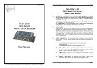
Issue <strong>12</strong>84UH 0509SALCOM <strong>12</strong>-84-0000SE <strong>POCSAG</strong> RECEIVER with RELAY OUTPUTS Issue <strong>12</strong><strong>84SE</strong>UH 0509<strong>12</strong>-84-0150SE VHF/<strong>12</strong>-84-0450SE UHF<strong>POCSAG</strong> 2 Relay Output <strong>Receiver</strong>GENERAL<strong>12</strong>-84-0000SE<strong>POCSAG</strong>RECEIVER/DECODERThe <strong>12</strong>-<strong>84SE</strong> <strong>POCSAG</strong> 2 Relay Output <strong>Receiver</strong> is available in two versions, a VHF <strong>12</strong>-84-0150 <strong>and</strong>a UHF <strong>12</strong>-84-0450 which provide two relay outputs which can be controlled remotely via SALCOMpaging systems or wide area paging networks.OPERATIONThe unit receives <strong>and</strong> decodes a numeric or alphanumeric pager call. If the received unit numbermatches the <strong>12</strong>-84 unit number or group number, the relay outputs are switched according to theON/OFF fields of the message.INSTALLATIONSituate the <strong>12</strong>-84 away from direct sunlight, vibration <strong>and</strong> strong heat sources <strong>and</strong> avoid close proximityto radio transmission equipment. The unit is not certified as intrinsically safe.In good coverage areas fit the aerial to the aerial socket as shown on the cover. An external aerial maybe needed where reception is poor.Connect a <strong>12</strong> volt DC power supply to the power terminals (see figure 1). The <strong>12</strong>-84 is protected againstreversed supply connection. The power source must be reasonably noise free.PRODUCT INFORMATIONThe connections to the relay contacts are made using the pairs of terminals, labelled ‘relay 1' <strong>and</strong> ‘relay2'. These are normally open contacts, but can be configured to be normally closed by special order.Relays are not to be connected directly to mains voltages.CORRECT OPERATIONThe operation of the unit is shown by the RED System LED. Correct operation is shown by this LEDflashing. If the LED does not light, check the voltage on the supply terminal block.During the reception of a valid comm<strong>and</strong> with the correct RIC code, this LED will stay on forapproximately one second. When a relay is comm<strong>and</strong>ed on, the corresponding LED will light next tothe active relay.SEA AIR & LAND COMMUNICATIONS LTD, CHRISTCHURCH, NEW ZEALANDSea Air <strong>and</strong> L<strong>and</strong> Communications Ltd Page 1
SALCOM <strong>12</strong>-84-0000SE <strong>POCSAG</strong> RECEIVER with RELAY OUTPUTS Issue <strong>12</strong><strong>84SE</strong>UH 0509SALCOM <strong>12</strong>-84-0000SE <strong>POCSAG</strong> RECEIVER with RELAY OUTPUTS Issue <strong>12</strong><strong>84SE</strong>UH 0509UNIT NUMBEREach unit will respond only to messages containing a matching Unit Number. Up to 99 unique unitnumbers are available. Any number of units can be programmed with the same unit number. The UnitNumber comprising of 2 digits is selected using the configuration software.MONOSHOTOutput mono-shot (momentary) operation can be enabled by using the configuration software. The Relayoutput can have its own Mono-shot time, ranging from 25mS to 30 minutes in 25mS steps. Setting thevalue to 0 disables the mono-shot timer altogether, <strong>and</strong> the relay output is latched until comm<strong>and</strong>ed off.COMMANDSThe OUTPUT Relay of the <strong>12</strong>-84 controlled by a series of numeric comm<strong>and</strong>s sent in the form of anumeric or alphanumeric pager message.Note: For best sensitivity <strong>and</strong> range, it is better to send the comm<strong>and</strong> as a numeric paging message,as this uses the least number of characters.UUComm<strong>and</strong> Format: UUx..x0y..y9Unit numberThis must be entered as 2 digits 00 - 99.RADIO CHANNEL FREQUENCYThe frequency of the radio channel is preset at the SALCOM factory. The nominal tuning range is: VHF148 to 161 MHz <strong>and</strong> UHF 450 to 470 MHz.xRelay to go ON.The st<strong>and</strong>ard relay in the <strong>12</strong>-84 is designated as channel 1. Therefore the comm<strong>and</strong> shouldcarry “1" in this position. If a second relay is fitted to the unit, this digit can be 1 or 2 or both.Any combination of Digits 1or 2 can be entered in any order. If none are entered then thefunction has no effect.SPECIFICATIONFrequency B<strong>and</strong>sVHF: 148-161MHz UHF: 450-470MHzEnclosure.135mm x 100mm x 30mm. extruded aluminium case.Supply Voltage 10v to 17v, Nominal <strong>12</strong>V.0 End entry of Output ON valuesThis terminates the list of outputs to turn on. This character in m<strong>and</strong>atory.y Relay to go OFF.As per “Relay to go ON” above, but this designates the relay to go OFF instead.9 End entry of Outputs OFF values & Ignore rest of entry.This terminates the list of outputs to turn OFF <strong>and</strong> Informs the <strong>12</strong>-84-0000 to ignore the restof the message. This allows a text message to follow the comm<strong>and</strong>.Current drainRelay contactsSt<strong>and</strong>by 60mA plus 18mA per energised relay.1Amp @24VDC (Not suitable for 240VAC connection)Examples:(All examples are for latching relay control, so “Hold Time” is set to 0. Examplesassume a unit id of 11):Temperature limits-10 to +50degCActionMessage ReceivedEnvironmental protectionNeeds protection from weatherTo close relay 1 11109Frequency selection methodSynthesized, programmable via <strong>Salcom</strong> <strong>12</strong>-<strong>84SE</strong> PSDTo open relay 1 11019RX sensitivitySerial OutputAerial connectionPaging protocolApprox -<strong>12</strong>4dBm9600 Baud N:8:1BNC connector. Supplied with aerial<strong>POCSAG</strong> 5<strong>12</strong> or <strong>12</strong>00baud, auto selected.To close relay 2 1<strong>12</strong>09To open relay 2 11029To close relay 1 <strong>and</strong> relay 2 together 11<strong>12</strong>09To open relay 1 <strong>and</strong> relay 2 together 110<strong>12</strong>9Sea Air <strong>and</strong> L<strong>and</strong> Communications Ltd Page 2Sea Air <strong>and</strong> L<strong>and</strong> Communications Ltd Page 3
SALCOM <strong>12</strong>-84-0000SE <strong>POCSAG</strong> RECEIVER with RELAY OUTPUTS Issue <strong>12</strong><strong>84SE</strong>UH 0509SALCOM <strong>12</strong>-84-0000SE <strong>POCSAG</strong> RECEIVER with RELAY OUTPUTS Issue <strong>12</strong><strong>84SE</strong>UH 0509<strong>12</strong>-84 SETUPThe programmable parameters of the <strong>12</strong>-84 can be configured using the SALCOM <strong>12</strong>-45 programmingcable (ordered separately) <strong>and</strong> the <strong>12</strong>-<strong>84SE</strong> PSD software which can be downloaded from the supportarea of the <strong>Salcom</strong> web page www.salcom.co.nz.(1) Connect the <strong>12</strong>-45 programming cable to the programming connector on the <strong>12</strong>-84 <strong>and</strong> to anyPC com port.(2) Apply power to the <strong>12</strong>-84.(3) Press the Connect button. If connecting is not successful, ensure that com port settings arecorrect.(4) Once connected, click on the Read button <strong>and</strong> the current setup of the target unit will be read<strong>and</strong> displayed.(5) Make any desired changes by entering data or modifying data in the appropriate fields.(6) Reprogram the unit by clicking the Program button to upload the changes to the <strong>12</strong>-84.PSD SETTINGSCom PortSerial communication port.ID2 character id which identifies this unit when the <strong>12</strong>-84 relay protocol is used.Rx Frequency The frequency to set receiver to. Note that there is only a minor adjustmentpossible (within a few MHz) that can be made until the receiver must be manuallyaligned again.Ref Frequency The receiver synthesizer reference frequency.Decode any RIC Checked: if all messages are to be decoded <strong>and</strong> sent to serial port. Messages,if not defined within a range are assumed to be alphanumeric.Unchecked: the receiver will only decode messages within valid ranges (notbeginning with 0000000) or using the <strong>POCSAG</strong> Rapid Relay control RIC.Relay Hold Times If relay hold times are set to 0, once turned on, a relay will stay on until instructedto turn off. If a relay hold time is set, a relay when turned on will turn off againafter the Hold Time (in ms) has elapsed. If <strong>POCSAG</strong> Rapid is used this Hold Timeshould not be less than 150ms for reliable operation (otherwise the relays willchatter).Pocsag Rapid When selected, the <strong>Receiver</strong> will check more frequently for the preamble, <strong>and</strong>therefore support the 64 bit preamble that precedes the <strong>Salcom</strong> <strong>POCSAG</strong> Rapidformat. When enabled the Relay Control RIC is checked <strong>and</strong> used if matched.Relay Control This is the <strong>POCSAG</strong> Rapid control RIC. This RIC also includes the 7 RIC codesfollowing the one specified. Pocsag Rapid transmitters will use the <strong>Salcom</strong> relaycontrol protocol that will control the 2 on board relays. Decoded messagesmatched to the Relay control RIC are not sent out the serial port.Receive Ranges Describes a ranges of RICs that should be managed in a similar fashion. Todisable a range, set the first RIC in the range to 0000000.Min RICThe RIC code between 8 <strong>and</strong> 2000000 that identifies the beginning of the range.Max RICThe RIC code between 8 <strong>and</strong> 2000000 that identifies the end of the range. MaxRIC may be the same as the min RIC, but may not be less than the min RIC.DecodeDescribes how the messages matched in this range will be decoded(alphanumeric or numeric).Monitor Action If a RIC is matched in this Range this action will be performed, either no action, closerelay 1 or relay 2.Note: this type of relay control is more vulnerable to false triggering than using therelay control protocol. This should not be used for general relay control , usingthe relay control protocol is the preferred method.OPTIONSSome options are available for the <strong>12</strong>-84 to extend its use to other situations. These options can onlybe fitted by the SALCOM factory <strong>and</strong> must be requested at the initial order.(1) An external aerial can be fitted by unplugging the existing aerial <strong>and</strong> plugging in the BNC aerialconnector on the coaxial aerial lead.(2) Fitted relays can be installed as normally closed.Sea Air <strong>and</strong> L<strong>and</strong> Communications Ltd Page 4Sea Air <strong>and</strong> L<strong>and</strong> Communications Ltd Page 5
SALCOM <strong>12</strong>-84-0000SE <strong>POCSAG</strong> RECEIVER with RELAY OUTPUTS Issue <strong>12</strong><strong>84SE</strong>UH 0509SALCOM <strong>12</strong>-84-0000SE <strong>POCSAG</strong> RECEIVER with RELAY OUTPUTS Issue <strong>12</strong><strong>84SE</strong>UH 0509CONNECTIONSSERIAL DATA OUTPUTIf the need arises to monitor paging messages on a network, the <strong>12</strong>-84 can provide serial data output(9600 Baud N:8:1) via the progamming connector. The <strong>12</strong>-84 can be connected to the serial port of aPC using a <strong>Salcom</strong> <strong>12</strong>-45 programming lead. The format of the output string is as follows:5<strong>12</strong>.A.S.0.<strong>12</strong>34567 TXT CR5<strong>12</strong>/<strong>12</strong>00 = Baud RateA or N = Alpha or NumericS or I= (S) non inverted (I) inverted0 = Level<strong>12</strong>34567 = RICTXT= messageCR= Carriage return<strong>Salcom</strong>’s VisualPET paging software can be used to log the received data.WARRANTYFigure 1Pin numbering: looking into the sockets with the power connectoron the left, pin 1 is on the left.Our Products are warranted for a period of <strong>12</strong> months from date of purchase against faulty materials <strong>and</strong>workmanship. Should any fault occur the unit should be returned to the vendor, freight pre-paid. Pleaseinclude a description of the fault to assist with prompt return. Any unauthorized alterations or repairs willinvalidate the warranty.S2 RJ<strong>12</strong> - 6 WAYPROGRAMMING PORTS10 RJ45 - 8 WAY RELAYCONNECTION PORTPin Description Pin Description1 Ground 1 Unused2 System LED 2 Unused3 Unused 3 Relay 2 Normally OpenDISCLAIMERAll information provided in this document is carefully prepared <strong>and</strong> offered in good faith as a guide in theinstallation, use <strong>and</strong> servicing of our products. Installers must ensure that the final installation operatessatisfactorily within the relevant regulatory requirements. We accept no responsibility for incorrectinstallation.We reserve the right to change products, specifications, <strong>and</strong> installation data at any time, without notice.4 Power LED 4 Relay 2 Normally Closed5 RS232 out 5 Relay 2 Common6 RS232 in 6 Relay 1 Normally Open7 Relay 1 Normally Closed8 Relay 1 CommonSEA AIR & LAND COMMUNICATIONS LTDPO Box 22-621, <strong>12</strong>0 St.Asaph Street, Christchurch, New Zeal<strong>and</strong>Phone: (03) 379-2298 Fax: (03) 365-1580 Email: info@salcom.co.nzVisit us at www.salcom.co.nzSea Air <strong>and</strong> L<strong>and</strong> Communications Ltd Page 6Sea Air <strong>and</strong> L<strong>and</strong> Communications Ltd Page 7