DOWNLOAD 11-62 POCSAG Paging Transmitter Product ... - Salcom
DOWNLOAD 11-62 POCSAG Paging Transmitter Product ... - Salcom
DOWNLOAD 11-62 POCSAG Paging Transmitter Product ... - Salcom

You also want an ePaper? Increase the reach of your titles
YUMPU automatically turns print PDFs into web optimized ePapers that Google loves.
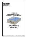
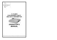
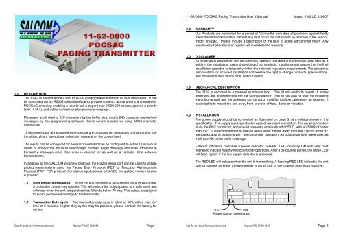
<strong>11</strong>-<strong>62</strong>-0000 <strong>POCSAG</strong> Pading <strong>Transmitter</strong> User’s Manual Issue: <strong>11</strong><strong>62</strong>UD 1206072.0 WARRANTYOur <strong>Product</strong>s are warranted for a period of 12 months from date of purchase against faultymaterials and workmanship. Should any fault occur the unit should be returned to the vendor,freight pre-paid. Please include a description of the fault to assist with prompt return. Anyunauthorized alterations or repairs will invalidate the warranty.3.0 DISCLAIMERAll information provided in this document is carefully prepared and offered in good faith as aguide in the installation, use and servicing of our products. Installers must ensure that the finalinstallation operates satisfactorily within the relevant regulatory requirements. We accept noresponsibility for incorrect installation and reserve the right to change products, specifications,and installation data at any time, without notice.1.0 DESCRIPTIONThe <strong>11</strong>-<strong>62</strong> is a stand-alone 4 watt <strong>POCSAG</strong> paging transmitter with an in-built encoder. It canbe controlled via an RS232 serial interface to provide numeric, alphanumeric and tone-only<strong>POCSAG</strong> encoding enabling a user to call a pager (over 2,000,000 codes), append a prioritylevel (1 of 4), and add a numeric or alphanumeric message.Messages are limited to 120 characters by the buffer size, and to 240 character pre-definedmessages by the programming software. Serial control is achieved using ASCII charactercommands.12 discrete inputs are supported with unique pre-programmed messages on high and/or lowtransition, plus a low voltage detection message on the power input.The inputs can be configured for several options and can be configured to act as 12 individualinputs or binary code inputs to select pager number, pager message and level. Provision totransmit a message more than once is catered for as well as a variable time betweentransmissions.In addition to the SALCOM propriety protocol, the RS232 serial port can be used to initiatepaging transmissions using the <strong>Paging</strong> Entry Protocol (PET) or Telocator AlphanumericProtocol (TAP) PG1 protocol. For dial-up applications, a HAYES compatible modem is alsosupported.4.0 MECHANICAL DESCRIPTIONThe <strong>11</strong><strong>62</strong> is enclosed in a pressed aluminium box. The lid will unclip to reveal 16 screwterminals, and adjustment for the low supply detector. The lid can also be used for mountingthe unit on a wall, and the overhang can be cut or modified to allow cable entry as required. Itis advisable to mount the unit away from sources of heat, damp or vibration.5.0 INSTALLATIONThe power supply should be connected as illustrated on page 3, at a voltage shown in thespecification. The supply input is protected against reversed connection. The aerial connectionis via the BNC connector, and should present a nominal load of 50 Ω, with a VSWR of betterthan 1.8:1. It is recommended to site the aerial a few metres away from the <strong>11</strong><strong>62</strong> to avoid RFfeedback causing problems with the transmitter operation. An outside aerial is preferable, asit will provide better radio coverage.External indicators comprise a power indicator GREEN LED, normally ON with very briefflashes to indicate healthy microcontroller operation. After a de-bounce period, the green LEDwill flash rapidly if the low supply detector is activated.The RED LED will indicate when the unit is transmitting. A flashing RED LED indicates the unitcannot transmit as either the synthesiser is out of lock or the channel busy input is active.1.1 Over temperature cutout: When the unit transmits at full power in a hot environment,a protective cutout may operate. This will reduce the output power to a safe level, andwill reset when the unit temperature has fallen to below 70 deg. This cutout is designedto avoid permanent damage to the transmitter.1.2 <strong>Transmitter</strong> Duty cycle: The transmitter duty cycle is rated as 50% with a max ‘on’time of 5 minutes. Higher duty cycles may be possible, please contact the factory foradvice.Sea Air and Land Communications Ltd Manual IPN: 57-39-0045 Page 1Sea Air and Land Communications Ltd Manual IPN: 57-39-0045 Page 2
<strong>11</strong>-<strong>62</strong>-0000 <strong>POCSAG</strong> Pading <strong>Transmitter</strong> User’s Manual Issue: <strong>11</strong><strong>62</strong>UD 120607<strong>11</strong>-<strong>62</strong>-0000 <strong>POCSAG</strong> Pading <strong>Transmitter</strong> User’s Manual Issue: <strong>11</strong><strong>62</strong>UD 1206076.0 OPERATIONThe <strong>11</strong><strong>62</strong> can transmit three types of <strong>POCSAG</strong> message, with any one of four function levels:• Alphanumeric transmissions. Message can contain any alphanumeric ‘ASCII’ character.• Numeric transmissions. Message contains only Numeric characters and some symbols.• Tone Only transmissions (Alphanumeric or numeric with no message)6.1 Alphanumeric transmissionsMessages can contain any alphanumeric character . The <strong>11</strong><strong>62</strong> will accept the standardASCII 7 bit character set.6.2 Numeric transmissionsMessages can contain numeric characters and some symbols. These can convey atelephone number, or other numerically coded information. The transmitted message isshorter, and therefore there is a smaller chance of errors received by the pager.The numeric character set is as follows:0 1 2 3 4 5 6 7 8 9 [ ] - E U Note. The E may be displayed as P or * on different pagers6.3 Tone Only transmissionsAny numeric or alphanumeric paging message without an actual text message is alsoconsidered ‘Tone Only’. A function level will control the number of beeps on the receiver(four different function levels can be sent).7.0 INITIATING TRANSMISSIONSThere are four ways of initiating a paging message transmission:(1) Using the external discrete inputs (action)(2) Low supply detector threshold (action)(3) Watchdog (action)(4) RS232 Serial commandsAn action is defined as a paging message, RIC (Receiver Identification Code or capcode) andflags. These flags are discussed in the PSD (product support disk) section.7.1 External Discrete InputsAn action can be initiated from the twelve external inputs with an input transition to LOW(connection to GND) and/or HIGH (input floating or connection to >+3.5v).7.2 Low supply messageAfter a de-bounce period, the low-supply detector can initiate an action for both “supplygoing high” and “supply going low” conditions.7.3 WatchdogThe watchdog feature will initiate an action after a predetermined period. The watchdogtimer can be restarted (optionally) by any other action.7.4 Using the RS232 Serial CommandsSerial commands can be “manually” issued to an <strong>11</strong>-<strong>62</strong> using a terminal program suchas PROCOMM or Hyper-terminal. Tone only, numeric and alphanumeric pagers can becalled using serial commands. These commands will be processed in parallel with otherinputs actions for transmission. Some basic commands are described in section 7.4.1.Information on the full protocol command set is available in request.7.4.1 Protocol Command SetCAUsage: CA[][/]Description: Call alphanumeric pagerExample: CA<strong>11</strong>9358 1 Please return to receptionResponse: CA0<strong>11</strong>93581Page SentExample 2: CA<strong>11</strong>9358 1Please return to receptionResponse 2: CA0<strong>11</strong>93581MSG?Page SentCNUsage: CN[][/]Description: Call numeric pagerExample: CN<strong>11</strong>9358 1 777Response: CN0<strong>11</strong>93581Page SentExample 2: CN<strong>11</strong>9358 1777Response 2: CN0<strong>11</strong>93581MSG?Page SentCPUsage:Description:Example:Response:CP[]Call tone-only pagerCP0<strong>11</strong>93581CP0<strong>11</strong>93581Page SentSea Air and Land Communications Ltd Manual IPN: 57-39-0045 Page 3Sea Air and Land Communications Ltd Manual IPN: 57-39-0045 Page 4
<strong>11</strong>-<strong>62</strong>-0000 <strong>POCSAG</strong> Pading <strong>Transmitter</strong> User’s Manual Issue: <strong>11</strong><strong>62</strong>UD 120607<strong>11</strong>-<strong>62</strong>-0000 <strong>POCSAG</strong> Pading <strong>Transmitter</strong> User’s Manual Issue: <strong>11</strong><strong>62</strong>UD 120607HELPUsage:Description:Example:Response:MAPUsage:Description:Example:Response:RESUsage:Description:Example:Response:SN?Usage:Description:Example:Response:HELP [topic]Shows available commands or help on a particular commandHELP CPCA[ ]Call alphanumeric pagerMAPShow details of current configurationMAPRESReset <strong>11</strong>-<strong>62</strong> microcontrollerRESSALCOM Data <strong>Transmitter</strong> <strong>11</strong>-<strong>62</strong>ATS0=0 (Optional HAYES initialisation string)SN?Retrieve unit serial number and firmware revisionSN?SALCOM Data <strong>Transmitter</strong> <strong>11</strong>-<strong>62</strong>-9999 100 98<strong>11</strong> A9.0 PROGRAMMING9.1 Connecting the Programming Software:The programmable parameters of the <strong>11</strong>-<strong>62</strong> can be configured using a serial cable andthe MultiPSD software which can be downloaded from the support area of the <strong>Salcom</strong>website www.salcom.co.nz. Connect the serial cable from the <strong>11</strong>-<strong>62</strong> D9 socket to any PC comm port and applypower to the <strong>11</strong>-<strong>62</strong>.MultiPSD should display CONNECTED at the bottom of the screen and the screenshould change to the setup screen for the target unit.If DISCONNECTED is still displayed, check that the correct comm port is selected byselecting Change Comm Port in the Setup menu. Select the correct comm port from thelist of available comm ports displayed.Once connected, click on the Read Configuration button and the current setup of thetarget unit will be read and displayed.Information about the settings and operation of the software can be accessed via thebuilt in help function of the MultiPSD software by pressing F1 or selecting Help from theHelp menu.7.4.2 Error Codes/ReportsER1 SYNTAX You entered an invalid commandER3 OPERND You entered a valid command with invalid valuesProgramming of the <strong>11</strong>-<strong>62</strong> should be performed only by suitably qualified personnel.8.0 TROUBLE SHOOTINGIf the <strong>11</strong><strong>62</strong> does not perform as required, the following points may lead to solving the problem.FaultCheckNo illumination of Green LEDBad power supply connectionInput activated but no transmission PSD configuration incorrectUnit transmits but nothing received Poor aerial. Wrong frequency, RIC, baud-rate.Power too low. Unit too hot. Too muchvibrationNo RS232 serial communication Comport connections, baud-rate (1200-9600)no parity, eight data bits, one stop bitNo synthesizer lock. Red LED flashes VCO loop, Channel busy active.rapidlyGreen led flashes rapidlyLow supply detector thresholdUnit starts, but does not complete Poor supply volts, RF interference.transmissionSea Air and Land Communications Ltd Manual IPN: 57-39-0045 Page 5Sea Air and Land Communications Ltd Manual IPN: 57-39-0045 Page 6
<strong>11</strong>-<strong>62</strong>-0000 <strong>POCSAG</strong> Pading <strong>Transmitter</strong> User’s Manual Issue: <strong>11</strong><strong>62</strong>UD 1206079.2 Using the Programming Software:MultiPSD allows the user to configure the following characteristics:• Input actions, watchdog, low supply detector, GPS transmission and <strong>POCSAG</strong>transmission settings• Pre-defined messages• RF frequency and output power• RS232 configuration• 100 pager numbersOnce the program is running, the opening screen appears. Use the mouse to select theconfiguration fields for each feature. At any time context sensitive help is available bypressing F1.The diagram above shows the cable connections for both 9 pin and 25 pin serial ports.The serial comm port has connections to match the standard DB9 RS232 pin-out.10.0 SPECIFICATIONSPower SupplyRF FrequencyChannel SpacingOutput PowerPower ConsumptionModulationDeviationBaud rateMessage formatSpurious OutputsSerial input/outputSerial paging commandprotocolsDiscrete inputsDiscrete outputs+<strong>11</strong>.5 V to 15.2 V nom 13.8 V138 - 170 MHz12.5 KHz or 25 KHz4 Watts +/- 1 dB 50Ω (25 Watts optional)Standby : 45 mA Low power standby - 15 mATransmit: 800 mA approxCarrier FSK with NRZ data+/-4.5kHz or +/-2.5kHz512/1200/1600/2400Baud<strong>POCSAG</strong>-30dBm or lessRS-232 (DCE), 1200-9600 baud no parity,8 data bits, 1 stop bitSALCOM proprietary, PET (PG1)GPS (NMEA $GPGGA)Pulled up to +12v (47K), ground to activate+12v on P5 pin 1 (200mA max).+12v switched P5 pin 9 (200mA max)PTT & Data on P7 pins 5 and 9(20mA sink with 47K pull-up to 5 V)Case Dimensions140 x 105 x 32mmType ApprovalsNew Zealand - Australia AS4295Transmit duty cycle Up to 50%Sea Air and Land Communications Ltd Manual IPN: 57-39-0045 Page 7SEA AIR & LAND COMMUNICATIONS LTDPO Box 22-<strong>62</strong>1, 120 St.Asaph Street, Christchurch, New ZealandPhone: (03) 379-2298 Fax: (03) 365-1580 Email: info@salcom.co.nzVisit us at www.salcom.co.nz