11-97-0000 1200 BAUD RADIO DATA MODEM User Manual - Salcom
11-97-0000 1200 BAUD RADIO DATA MODEM User Manual - Salcom
11-97-0000 1200 BAUD RADIO DATA MODEM User Manual - Salcom

You also want an ePaper? Increase the reach of your titles
YUMPU automatically turns print PDFs into web optimized ePapers that Google loves.
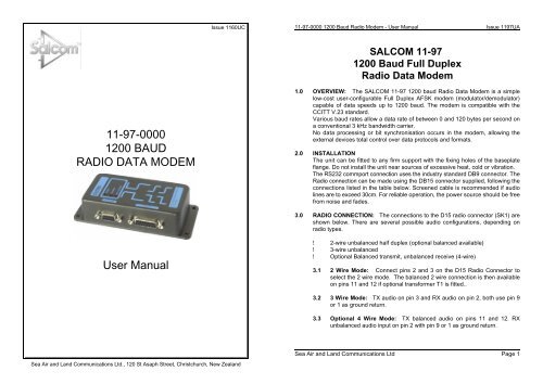
Issue <strong>11</strong>60UC<strong>11</strong>-<strong>97</strong>-<strong>0000</strong> <strong>1200</strong> Baud Radio Modem - <strong>User</strong> <strong>Manual</strong> Issue <strong>11</strong><strong>97</strong>UASALCOM <strong>11</strong>-<strong>97</strong><strong>1200</strong> Baud Full DuplexRadio Data Modem<strong>11</strong>-<strong>97</strong>-<strong>0000</strong><strong>1200</strong> <strong>BAUD</strong><strong>RADIO</strong> <strong>DATA</strong> <strong>MODEM</strong>1.0 OVERVIEW: The SALCOM <strong>11</strong>-<strong>97</strong> <strong>1200</strong> baud Radio Data Modem is a simplelow-cost user-configurable Full Duplex AFSK modem (modulator/demodulator)capable of data speeds up to <strong>1200</strong> baud. The modem is compatible with theCCITT V.23 standard.Various baud rates allow a data rate of between 0 and 120 bytes per second ona conventional 3 kHz bandwidth carrier.No data processing or bit synchronisation occurs in the modem, allowing theexternal devices total control over data protocols and formats.2.0 INSTALLATIONThe unit can be fitted to any firm support with the fixing holes of the baseplateflange. Do not install the unit near sources of excessive heat, cold or vibration.The RS232 commport connection uses the industry standard DB9 connector. TheRadio connection can be made using the DB15 connector supplied, following theconnections listed in the table below. Screened cable is recommended if audiolines are to exceed 30cm. For reliable operation, the power source should be freefrom noise and fades.3.0 <strong>RADIO</strong> CONNECTION: The connections to the D15 radio connector (SK1) areshown below. There are several possible audio configurations, depending onradio types.<strong>User</strong> <strong>Manual</strong>! 2-wire unbalanced half duplex (optional balanced available)! 3-wire unbalanced! Optional Balanced transmit, unbalanced receive (4-wire)3.1 2 Wire Mode: Connect pins 2 and 3 on the D15 Radio Connector toselect the 2 wire mode. The balanced 2 wire connection is then availableon pins <strong>11</strong> and 12 if optional transformer T1 is fitted..3.2 3 Wire Mode: TX audio on pin 3 and RX audio on pin 2, both use pin 9or 1 as ground return.3.3 Optional 4 Wire Mode: TX balanced audio on pins <strong>11</strong> and 12. RXunbalanced audio input on pin 2 with pin 9 or 1 as ground return.Sea Air and Land Communications Ltd Page 1Sea Air and Land Communications Ltd., 120 St Asaph Street, Christchurch, New Zealand
<strong>11</strong>-<strong>97</strong>-<strong>0000</strong> <strong>1200</strong> Baud Radio Modem - <strong>User</strong> <strong>Manual</strong> Issue <strong>11</strong><strong>97</strong>UA <strong>11</strong>-<strong>97</strong>-<strong>0000</strong> <strong>1200</strong> Baud Radio Modem - <strong>User</strong> <strong>Manual</strong> Issue <strong>11</strong><strong>97</strong>UA5.0 <strong>11</strong>-<strong>97</strong>-<strong>0000</strong> CONFIGURATION SELECTIOND15 <strong>RADIO</strong> CONNECTOR (SK1)Pin 1, Pin 9GroundPin 2 Unbalanced audio in (10Kohm) (Optional 600R)Pin 3Pin 5Pin 7Pin 10, 13Pin <strong>11</strong>, Pin 12Pin 8, Pin 15Unbalanced audio out (600 ohm)PTT output (open collector)Channel busy input (internal +12v pull up).Not usedBalanced audio (600ohm)Supply voltage input4.0 COMMS CONNECTION: The <strong>11</strong>-<strong>97</strong> modem has a D9 RS232 communicationssocket (SK2) configured as DCE (Data Communication Equipment). Connectionto an IBM PC or compatible computer, laptop or DTE (Data Terminal Equipment)is via a straight-through D9 plug to D9 socket cable, with an optional D9-D25adapter.Generally the handshaking connections have the following functions:RTS input to the <strong>11</strong><strong>97</strong> is used for controlling the PTT output of the unit.CTS output from the <strong>11</strong><strong>97</strong> is used to show the state of the busy input from theradio.DCD output from the <strong>11</strong><strong>97</strong> reflects the state of the carrier detector in the modem.The Received Data output is gated OFF when Carrier Detect is not active. Thisprevents erroneous data being generated by noise on the RX audio input.D9 COMMUNICATIONS CONNECTOR (SK2)Pin 1 Carrier detect (output from <strong>11</strong>-<strong>97</strong>)Pin 2 Transmit data (output from <strong>11</strong>-<strong>97</strong>)Pin 3 Receive data (input to <strong>11</strong>-<strong>97</strong>)Pin 4Pin 5Pin 6Data Set Ready (tied to DTR)GroundData Terminal Ready (tied to DSR)Pin 7 Ready to Send (input to <strong>11</strong><strong>97</strong>)Pin 8 Clear to Send (output from <strong>11</strong>-<strong>97</strong>)5.1 Link headers: The modem can be configured using the links providedon the PCB.LNK1 Data Carrier HI: DCD goes high on carrier detect.Detect phaseLOW:DCD goes low on carrier detectLNK2 Busy Input HI: Expects High on input for chan busyphaseLOW:Expects Low on input for chanbusyLNK3 PTT ON: CTS controlled by PTTloopbackenable OFF:Routes RTS to PTT outputLNK4 Power Save On: RS232 drivers only on when radiomode enable busy.Off: RS232 drivers always on.LNK5 Auto PTT RTS:PTT derived from RTS inputfunctionTD:PTT derived from first data bit.5.2 Carrier Detect output DCD phase link select:The DCD output can show an active high or low signal depending on theposition of LNK1.5.3 BUSY phase link select:The busy input can expect an active high or low signal depending on theposition of LNK2.5.4 PTT loopback mode:For some PLC installations, the PTT signal must be looped back to theCTS output, thus making sure the sending equipment will not decodeerroeous received data. When using this function, the BUSY Input Phaselink must be in the LOW position.5.5 Power Save mode:The RS232 line drivers consumes a large part of the total power of the<strong>11</strong><strong>97</strong> modem. These drivers can be always turned on, or only turned onwhen the radio busy signal goes active. The RS232 inputs (RTS,RD) willstill be active in the powerdown state.Warning: The DCD signal will be disabled when the <strong>11</strong><strong>97</strong> is in thepower down state.At unmanned solar powered sites, further power saving can be acheivedSea Air and Land Communications Ltd Page 2 Sea Air and Land Communications Ltd Page 3
<strong>11</strong>-<strong>97</strong>-<strong>0000</strong> <strong>1200</strong> Baud Radio Modem - <strong>User</strong> <strong>Manual</strong> Issue <strong>11</strong><strong>97</strong>UA <strong>11</strong>-<strong>97</strong>-<strong>0000</strong> <strong>1200</strong> Baud Radio Modem - <strong>User</strong> <strong>Manual</strong> Issue <strong>11</strong><strong>97</strong>UAby disconnecting the LED indicators, to be performed by SALCOM onrequest.5.6 Auto PTT function:When the DTE equipment cannot provide aRTS signal to initiate the PTTof the radio, the AUTO PTT function may be used. In this mode, the PTToutput will go active after the first data bit is received on the RS232transmitdatainput (pin3). The PTT will hang on for a short period, allowing aconsecutive series of data to be transmitted.Warning. This function relies on thedata string to be continuous, andthe first few data bits will be lost due to RX/TX switching delays in theradio, hence a data preamble must be added to the begining of thestring.5.7 Level Controls.The onboard control RV1 changes the transmit audio level. This allowsthe radio modulation to be correctly adjusted.PTTLoop BackLinkRTStest pointAuto PTTselectRXAudiotest pointSelect phaseof DCD outputOptionalterminantionBusy Test pointSK2RS232 ConnectorSK1Radio ConnectorReceivedatatest pointSelectphaseof BusyInputTransmitdatatest pointCTStestpointPowerSaveMode LinkPTTtestpointTXaudiotest pointAdjust Audiooutput levelto radioDefault position of LinksLayout of <strong>11</strong><strong>97</strong> modem showingtest points, Links and adjusters.Sea Air and Land Communications Ltd Page 4 Sea Air and Land Communications Ltd Page 5
<strong>11</strong>-<strong>97</strong>-<strong>0000</strong> <strong>1200</strong> Baud Radio Modem - <strong>User</strong> <strong>Manual</strong> Issue <strong>11</strong><strong>97</strong>UA6.0 WARRANTY: Our products are warranted for a period of 12 months frompurchase date against faulty materials and workmanship. If any fault occurs,return the unit to the vendor, freight pre-paid. Include a description of the faultto assist with prompt return. Unauthorized alterations or repairs will invalidate thewarranty.7.0 DISCLAIMER: Information provided in this document is offered in good faith asa guide in the installation, use and servicing of our products. Installers mustensure that the installation operates within the relevant regulatory requirements.We accept no responsibility for incorrect installation. We reserve the right tochange products, specifications, and installation data at any time, without notice.8.0SPECIFICATIONSType Number SALCOM IPN: <strong>11</strong>-<strong>97</strong>-<strong>0000</strong>Input VoltageInput CurrentRS232 interfaceRS232 outputsRS232 inputsData RatesRadio/line interfaceAudio inputCarrier Detect AF levelAudio outputOn-air tone setPTT hold onPTT OutputBusy InputCase Dimensions8-24 volts DC (nom 12 volts)Approximately 30mA when idle.Approx 17mA in power save mode.D9 Socket (DCE)Received data, CTS for radio busy, DCD for modemcarrier detect.Transmit Data, RTS for PTT0 to <strong>1200</strong> BaudD15 Socket2-wire unbalanced 10kO. Optional 600 OLevel 25mV to 10V RMS. 250mV RMS nominal30mVrmsUnbalanced 600 O, Balanced 600 OLevel 50mVRMS into 10k nom, Variable 10 to600mVrms2 tone AFSK. CCITT V.23 and ETSI compatible.PTT will hold on for 100mS after RTS goes inactive.Active Low Open Collector. Imax 100mA. Vmax 30VLink selectable phase, Active High or Low.Pulled high to +vsupply through 100k132 x 60 x 30 mmSEA AIR & LAND COMMUNICATIONS LTDPO Box 22-621, 120 St.Asaph Street, Christchurch, New ZealandPhone: (03) 379-2298 Fax: (03) 365-1580 Email: info@salcom.co.nzWeb Page: www.salcom.co.nzSea Air and Land Communications Ltd Page 6