DOWNLOAD 11-78 Synthesized 4 Watt NRZ Data ... - Salcom
DOWNLOAD 11-78 Synthesized 4 Watt NRZ Data ... - Salcom
DOWNLOAD 11-78 Synthesized 4 Watt NRZ Data ... - Salcom

You also want an ePaper? Increase the reach of your titles
YUMPU automatically turns print PDFs into web optimized ePapers that Google loves.
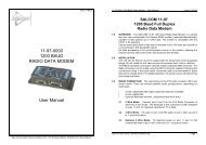
<strong>11</strong>-<strong>78</strong>-0000SYNTHESIZED 4 WATT<strong>NRZ</strong> DATA TRANSMITTEROPERATOR’SMANUALSea Air and Land Communications Ltd, PO Box 22-621, 120 St Asaph Street, Christchurch, New Zealand
<strong>11</strong>-<strong>78</strong>-0000 SYNTHESIZED <strong>NRZ</strong> DATA TRANSMITTER OPERATOR’S MANUAL Issue B <strong>11</strong>-<strong>78</strong>-0000 SYNTHESIZED <strong>NRZ</strong> DATA TRANSMITTER OPERATOR’S MANUAL Issue B<strong>11</strong>-<strong>78</strong> <strong>NRZ</strong>DATA TRANSMITTER1.0 DESCRIPTIONThe <strong>11</strong>-<strong>78</strong> is a stand-alone 4 watt <strong>NRZ</strong> data paging transmitter. It has aspecial modulator design capable of transmitting frequency shift keying downto DC, using a dual point modulation synthesizer.The unit can be configured via an RS232 serial interface adapter (SALCOM<strong>11</strong>-46) using the Product Support Disk (PSD) programming software.The unit supports three inputs, PTT, DATA and BUSY. An internal data delaycan be selected for use in simulcast networks, and a “maximum on air timer”(MOAT) can be implemented.An independent PTT output is available, controlled by the MOAT or BUSYfunctions, for enabling external power amplifiers or aerial changeover relays.External control of channel change is also available.1.1 Year 2000 compliance statement: SALCOM has made every efforttowards year 2000 compliant systems and software. However, as ourproducts are often used as system integration tools or rely on othersystems, we cannot fully determine their behaviour in everyenvironment.Full Y2K Compliance can be defined as follows:(1) No value for current date will cause any interruption inoperation(2) Date based functionality must behave consistently fordates prior to, during and after year 2000(3) In all interfaces and data storage, the century in any datemust be specified either explicitly or by unambiguousalgorithms or rules (like a 'pivot' date)(4) Year 2000 must be recognized as a leap yearThe <strong>11</strong>-<strong>78</strong>-0000 has no internal time or date reference. It is thereforeinherently Year 2000 compliant.2.0 WARRANTYOur Products are warranted for a period of 12 months from date of purchaseagainst faulty materials and workmanship. Should any fault occur the unitshould be returned to the vendor, freight pre-paid. Please include adescription of the fault to assist with prompt return. Any unauthorizedalterations or repairs will invalidate the warranty.3.0 DISCLAIMERAll information provided in this document is carefully prepared and offered ingood faith as a guide in the installation, use and servicing of our products.Installers must ensure that the final installation operates satisfactorily withinthe relevant regulatory requirements. We accept no responsibility forincorrect installation.We reserve the right to change products, specifications, and installation dataat any time, without notice.4.0 MECHANICAL DESCRIPTIONThe <strong>11</strong><strong>78</strong> is enclosed in a pressed aluminium box. All electrical connectionsare made via the D15 socket S2, or the two pin power connector provided.The lid can be used for mounting the unit on a wall. It is advisable to mountthe unit away from sources of heat, damp or vibration.5.0 INSTALLATIONThe configuration of the unit should be completed before installation.The power supply should be connected as illustrated, at a voltage shown inthe specification. The supply input is protected against reversed connection.The aerial connection is via the BNC connector, and should present anominal load of 50 O, with a VSWR of better than 1.8:1. It is recommendedto site the aerial a few metres away from the <strong>11</strong><strong>78</strong> to avoid RF feedbackcausing problems with the transmitter operation. An outside aerial ispreferable, as it will provide better radio coverage.External indicators consist of a power indicator GREEN LED, normally ONwith very brief flashes to indicate healthy micro-controller operation.The RED LED will indicate when the unit is transmitting. A flashing RED LEDindicates the unit cannot transmit as either the synthesiser is out of lock orthe channel busy input is active.Sea Air and Land Communications Ltd Page 1 Sea Air and Land Communications Ltd Page 2
<strong>11</strong>-<strong>78</strong>-0000 SYNTHESIZED <strong>NRZ</strong> DATA TRANSMITTER OPERATOR’S MANUAL Issue B <strong>11</strong>-<strong>78</strong>-0000 SYNTHESIZED <strong>NRZ</strong> DATA TRANSMITTER OPERATOR’S MANUAL Issue B6.0 OPERATION 9 PROGRAMMINGThe <strong>11</strong><strong>78</strong> will power on, and will remain in the standby mode until the PTT 9.1 Connecting the Programming adapter:input is activated.To change the configuration options, the unit must be connected via aSALCOM <strong>11</strong>-46 adapter to the serial port of a IBM PC compatible computerrunning the appropriate Product Support Disk (PSD) containing the software7.0 INITIATING TRANSMISSIONS (S<strong>11</strong><strong>78</strong>WE1.EXE) to program the <strong>11</strong>-<strong>78</strong>. This software can be obtained fromThe transmitter will be placed in transmit mode by the PTT (Press To Talk)input being taken low. It will then turn the carrier on at the preset power level,as defined in the configuration. The carrier frequency will follow the <strong>Data</strong>1input, a high input giving high frequency shift.our WEB site, shown below.<strong>Data</strong>2 input acts as a channel busy inhibit, when taken low it will stop thetransmitter coming on air.An input can be initiated with a transition to LOW (connection to GND orconnection to +3.5v).8.0 TROUBLE SHOOTINGIf the <strong>11</strong><strong>78</strong> does not perform as required, the following points may lead tosolving the problem.FaultNo illumination of Green LEDPTT input activated but notransmissionUnit transmits but nothing receivedCheckBad power supply connectionBusy inhibit input active.Poor aerial. Wrong frequency, Power toolow. Unit too hot. Too much vibrationNo RS232 serial communication Comport connections, baud-rate (9600)no parity, eight data bits, one stop bitRed LED flashes rapidly. Nosynthesizer lock.Unit starts, but does not completetransmissionDoes not remain in transmit modeFrequency out of range, Channel busyactive.Poor supply volts, RF interference.“Max On Air Time” too shortImportant: As some <strong>11</strong>-<strong>78</strong>'s are powered via S2 (D15 socket), the<strong>11</strong>-46 programmer D15 plug must have power connections added. Lift theprotective sponge and add 300mm black 10/.1 wire (gnd) to pin 1 and300mm red 10/.1 wire (+13.8V) to pin 8. Pin numbering can be had bytransposing back from the <strong>11</strong>-<strong>78</strong> socket. Connecting to a power supply willnot feed back to or harm the computer.Connect the SALCOM <strong>11</strong>-46 adapter to the 15way D type socket S2. To runthe PSD, place the disk into floppy drive A. At a DOS prompt, type A: S<strong>11</strong><strong>78</strong>WE1 .Correct communication between the <strong>11</strong>-<strong>78</strong> and the PC comm port isindicated by the ID and product number appearing in the bottom right handcorner of the screen. If these fail to appear, check the baud rate setting inFile/Preferences.9.2 USING THE PROGRAMMING SOFTWARE:Once the program is running, the opening screen appears . Use the arrowkeys or mouse to select various application layers and the configurationfields for each feature. At any time context sensitive help is available bypressing F1.The software allows the user to configure the following characteristics:C RF carrier frequencyC RF carrier frequency of alternate channelsC RF carrier powerC Maximum ON AIR time.C Low power operation in standbyC Simulcast delay.The RF Carrier frequency can be selected within a 6MHz band withoutadjustment of the VCO. Outside that band some adjustment may be needed.Contact SALCOM for details of this work.Sea Air and Land Communications Ltd Page 3 Sea Air and Land Communications Ltd Page 4
<strong>11</strong>-<strong>78</strong>-0000 SYNTHESIZED <strong>NRZ</strong> DATA TRANSMITTER OPERATOR’S MANUAL Issue B10 SPECIFICATIONSPower SupplyRF FrequencyChannel SpacingOutput Power+<strong>11</strong>.5 V to 15.2 V nom 13.8 V450 - 470 MHz12.5 KHz or 25 KHz4 <strong>Watt</strong>s ±1 dB 50 OPower Consumption Standby : 45 mA Low power standby - 15 mATransmit: 1A approxModulationDeviationBaud rateModulationSpurious OutputsSerial input/outputDiscrete inputsDiscrete outputsCase DimensionsType ApprovalsCarrier FSK with <strong>NRZ</strong> data±2.25kHz or ±4.5kHz512 or 1200 Baud<strong>NRZ</strong> FFSK-36dBm or lessRS-232 (DCE), 9600 baud no parity,8 data bits, 1 stop bitPulled up to +12v (47K), ground to activate.Threshold approx 3v+12v on P5 pin 8&15 (200mA max).PTT on S2 pins 7. (20mA sink with diode to 12 V)155 x <strong>11</strong>0 x 30mmTransmit duty cycle Up to 50%New Zealand - Australia AS4295Connections for S2Pin Function Pin Functionnumbernumber1 Ground 9 Not used2 Freq select 1 10 Freq select 23 <strong>Data</strong> Input 2 <strong>11</strong> Not used4 Freq select 3 12 Not used5 PTT input 13 <strong>Data</strong> Input 16 Serial TD 14 Serial RD7 PTT output 15 +12V output8 +12V outputSEA AIR & LAND COMMUNICATIONS LTDPO Box 22-621, 120 St.Asaph Street, Christchurch, New ZealandPhone: (03) 379-2298 Fax: (03) 365-1580 Email: info@salcom.co.nzVisit us at www.salcom.co.nzSea Air and Land Communications Ltd Page 5