V:\Products\12860000\Manual\1286-5000UB Op Manual ... - Salcom
V:\Products\12860000\Manual\1286-5000UB Op Manual ... - Salcom
V:\Products\12860000\Manual\1286-5000UB Op Manual ... - Salcom
- No tags were found...

You also want an ePaper? Increase the reach of your titles
YUMPU automatically turns print PDFs into web optimized ePapers that Google loves.
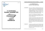
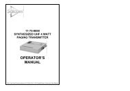
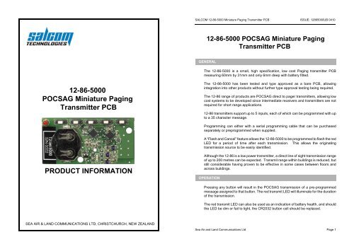
SALCOM 12-86-5000 Miniature Paging Transmitter PCB ISSUE: 1286<strong>5000UB</strong> 041012-86-5000 POCSAG Miniature PagingTransmitter PCBGENERALThe 12-86-5000 is a small, high specification, low cost Paging transmitter PCBmeasuring 60mm by 31mm and only 6mm deep with battery fitted.12-86-5000POCSAG Miniature PagingTransmitter PCBThe 12-86-5000 has been tested and type approved as a bare PCB, allowingintegration into other products without further type approval testing being required.The 12-86 range of products are POCSAG direct to pager transmitters, allowing lowcost systems to be developed since intermediate receivers and transmitters are notrequired for short range applications.12-86 transmitters support up to 5 inputs, each of which can be programmed with upto a 35 character message.Programming can either with a serial programming cable that can be purchasedseparately or preprogrammed when supplied.A “Flash and Cancel” feature allows the 12-86-5000 to be programmed to flash the redLED for a period of time after each transmission. This allows the originatingtransmission source to be easily identified.PRODUCT INFORMATIONAlthough the 12-86 is a low power transmitter, a direct line of sight transmission rangeof up to 200 metres can be expected. Transmit range within buildings is reduced, butstill considerable having proven to be effective in some cases between floors andacross buildings.OPERATIONPressing any button will result in the POCSAG transmission of a pre-programmedmessage assigned to that button. The red transmit LED will illuminate for the durationof the transmission.The red transmit LED can also be used as an indication of battery health, and shouldthe LED be dim or fail to light, the CR2032 button cell should be replaced.SEA AIR & LAND COMMUNICATIONS LTD, CHRISTCHURCH, NEW ZEALANDSea Air and Land Communications Ltd Page 1
SALCOM 12-86-5000 Miniature Paging Transmitter PCB ISSUE: 1286<strong>5000UB</strong> 0410SALCOM 12-86-5000 Miniature Paging Transmitter PCB ISSUE: 1286<strong>5000UB</strong> 0410PROGRAMMINGIn order to program the12-86-5000, programming software should be downloadedfrom the <strong>Salcom</strong> website (www.salcom.co.nz).A <strong>Salcom</strong> 12-47 programming lead is required to program the 12-86 transmitters (thesame lead used to program the 11-85 transmitters). This may be purchasedseparately. The 12-47 programming lead requires the availability of a PC with a serialport, running windows XP.Connect the 12-47 as shown below, with the dot (circled in yellow) on the 12-47socket towards the centre of the PCB (mating with the square pad).General ConfigurationButton Messages: Select the button to view the message, RIC and beep levelassigned to that button. New button settings can be entered, butwill not be written until the program button is pressed. Theprogram button only needs to be pressed after all button detailshave been populated.Frequency: The transmit frequency between 440 and 470MHz to be set,25kHz channel spacing.Pager Type: If set to “alphanumeric”, then any message can be set into themessage box, and can only be used with pagers that supportalphanumeric messages. When “numeric” is set then only0,1,2,3,4,5,6,7,8,9,0,[,],-,E and U characters can be used. Toneonly pagers are supported by leaving the message box empty.Beep Level: Pager beep priority set - 1 highest, 4 lowest.RIC Code: Pager ID. Valid codes are 0000008 to 2000000The 12-86 Programming Software allows the transmitter frequency and buttonmessages to be set.1 Press “Connect”. The red LED will light, as a message is transmitted. Afterthe message has been sent, the green LED above the 4 th button will light forapproximately 1 second. The status at the bottom of the 12-86 PSD willindicate if successfully connected.2 Press “Read”. The current configuration is read from the 12-86-5000.3 Make any required changes.4 Press the “Program” button.5 Press “Disconnect”, then remove programming lead.Sea Air and Land Communications Ltd Page 2Sea Air and Land Communications Ltd Page 3
SALCOM 12-86-5000 Miniature Paging Transmitter PCB ISSUE: 1286<strong>5000UB</strong> 0410SALCOM 12-86-5000 Miniature Paging Transmitter PCB ISSUE: 1286<strong>5000UB</strong> 0410“FLASH AND CANCEL” OPERATIONSPECIFICATIONThe 12-86-5000 supports a feature that can be enabled if required to provide indicationwhen a transmission has been sent. This may be desired in an application, such as arestaurant table top transmitter, to easily determine who was seeking assistance.The “Flash and Cancel” feature allows a flash duration to be set when a button is pressed,and also allows a button to be set as a “cancel” to stop any further flashing (for when serviceis no longer required, or call has been serviced). When the feature has been enabledfurther transmissions are not possible until the cancel button has been pressed, theprogrammed flash period has expired or the LED has been flashing for at least 30 seconds -this is to prevent transmitter misuse.To use this feature:Programming the message for any button as "****" will set the button as a flash cancelbutton. Any number of buttons can be set as a “cancel”. When a cancel button is pressedthe red LED will flash twice slowly, stopping any further flashing.“Flash and Cancel” operation is enabled by prepending the set message with [NNN] (whereN is exactly 3 digits enclosed in square brackets) e.g. to send the message “ServiceRequired” and then flash the LED for 90 seconds the button message should beprogrammed with “[090]Service Required”. The “[090]” part of the message would not betransmitted. The message “[999]Service Required” would flash the LED for up to 999seconds.Attempting to retransmit a message before pressing “cancel” within 30 seconds of the lasttransmission will result in the red LED rapidly flashing for approximately 1 second.Using this feature will decrease battery life only when actively flashing. A typical CR2032coin cell will operate the 12-86-5000 for up to 200 hours of constant flashing (orapproximately 1000 transmissions).RF FrequencyDimensions.Supply VoltagePower ConsumptionBattery LifeTemperature limitsEnvironmentalprotectionChannel SpacingOutput PowerModulationDeviationTransmit Duty CycleBaud RateDiscrete InputsUHF: 440-470MHz Synthesized.61mm x 31mm x 6mm.3 volt CR2032 button cell.Sleep:100nA, LED flashing:1mA,Transmit:48mAApprox 1000 transmissions. Approx 10 yearsstandby.-10 to +55deg, -30 to +60 on request.Needs protection from weather and shouldbe mounted in an enclosure. When usedwithout an enclosure the unit can bedamaged by ESD.25kHz-5dBmCarrier FSK with NRZ data+/-4.5kHzUp to 20%, 30 seconds continuous512 Baud5 Push buttons factory fitted. Can begrounded to remotely operate.Type Approvals AS/NZS 4769.1:2000 and EN 300 224-2.Tested to and meets FCC Part 90.AerialIntegrated PCBSea Air and Land Communications Ltd Page 4Sea Air and Land Communications Ltd Page 5
SALCOM 12-86-5000 Miniature Paging Transmitter PCB ISSUE: 1286<strong>5000UB</strong> 0410BATTERY REPLACEMENTCare must be taken when replacing the CR2032 coin cell. The battery must be fittedwith the ‘+’ up and the ‘-’ touching the PCB. Incorrect battery installation will rapidlydischarge the coin cell, and may damage the transmitter.After battery replacement, test that the 12-86 is functional by sending a test messageand verifying the red LED lights. If the unit fails to operate, remove battery, confirmcorrect battery orientation and reinsert.WARRANTYOur Products are warranted for a period of 12 months from date of purchase againstfaulty materials and workmanship.Should any fault occur the unit should be returned to the vendor, freight pre-paid.Please include a description of the fault to assist with prompt return.Any unauthorized alterations or repairs will invalidate the warranty.DISCLAIMERAll information provided in this document is carefully prepared and offered in goodfaith as a guide in the installation, use and servicing of our products.Installers must ensure that the final installation operates satisfactorily within therelevant regulatory requirements. We accept no responsibility for incorrect installation.We reserve the right to change products, specifications, and installation data at anytime, without notice.SEA AIR & LAND COMMUNICATIONS LTDPO Box 22-621, 120 St.Asaph Street, Christchurch, New ZealandPhone: (03) 379-2298 Fax: (03) 365-1580 Email: info@salcom.co.nzVisit us at www.salcom.co.nzSea Air and Land Communications Ltd Page 6