Download the Rubbery Owen Maintenance Manual in PDF Format
Download the Rubbery Owen Maintenance Manual in PDF Format
Download the Rubbery Owen Maintenance Manual in PDF Format
- No tags were found...

You also want an ePaper? Increase the reach of your titles
YUMPU automatically turns print PDFs into web optimized ePapers that Google loves.
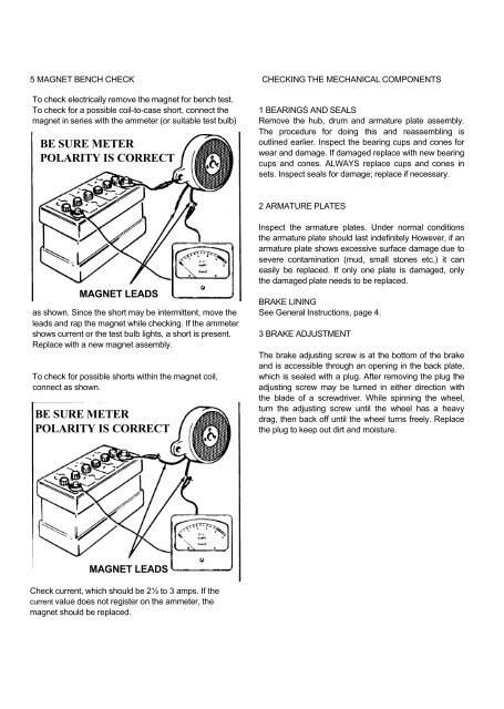
5 MAGNET BENCH CHECK CHECKING THE MECHANICAL COMPONENTSTo check electrically remove <strong>the</strong> magnet for bench test.To check for a possible coil-to-case short, connect <strong>the</strong>magnet <strong>in</strong> series with <strong>the</strong> ammeter (or suitable test bulb)BE SURE METERPOLARITY IS CORRECT1 BEARINGS AND SEALSRemove <strong>the</strong> hub, drum and armature plate assembly.The procedure for do<strong>in</strong>g this and reassembl<strong>in</strong>g isoutl<strong>in</strong>ed earlier. Inspect <strong>the</strong> bear<strong>in</strong>g cups and cones forwear and damage. If damaged replace with new bear<strong>in</strong>gcups and cones. ALWAYS replace cups and cones <strong>in</strong>sets. Inspect seals for damage; replace if necessary.2 ARMATURE PLATESMAGNET LEADSas shown. S<strong>in</strong>ce <strong>the</strong> short may be <strong>in</strong>termittent, move <strong>the</strong>leads and rap <strong>the</strong> magnet while check<strong>in</strong>g. If <strong>the</strong> ammetershows current or <strong>the</strong> test bulb lights, a short is present.Replace with a new magnet assembly.To check for possible shorts with<strong>in</strong> <strong>the</strong> magnet coil,connect as shown.BE SURE METERPOLARITY IS CORRECTInspect <strong>the</strong> armature plates. Under normal conditions<strong>the</strong> armature plate should last <strong>in</strong>def<strong>in</strong>itely However, if anarmature plate shows excessive surface damage due tosevere contam<strong>in</strong>ation (mud, small stones etc.) it caneasily be replaced. If only one plate is damaged, only<strong>the</strong> damaged plate needs to be replaced.BRAKE LININGSee General Instructions, page 4.3 BRAKE ADJUSTMENTThe brake adjust<strong>in</strong>g screw is at <strong>the</strong> bottom of <strong>the</strong> brakeand is accessible through an open<strong>in</strong>g <strong>in</strong> <strong>the</strong> back plate,which is sealed with a plug. After remov<strong>in</strong>g <strong>the</strong> plug <strong>the</strong>adjust<strong>in</strong>g screw may be turned <strong>in</strong> ei<strong>the</strong>r direction with<strong>the</strong> blade of a screwdriver. While sp<strong>in</strong>n<strong>in</strong>g <strong>the</strong> wheel,turn <strong>the</strong> adjust<strong>in</strong>g screw until <strong>the</strong> wheel has a heavydrag, <strong>the</strong>n back off until <strong>the</strong> wheel turns freely. Replace<strong>the</strong> plug to keep out dirt and moisture.MAGNET LEADSCheck current, which should be 2½ to 3 amps. If <strong>the</strong>current value does not register on <strong>the</strong> ammeter, <strong>the</strong>magnet should be replaced.