Download the Rubbery Owen Maintenance Manual in PDF Format
Download the Rubbery Owen Maintenance Manual in PDF Format
Download the Rubbery Owen Maintenance Manual in PDF Format
- No tags were found...

Create successful ePaper yourself
Turn your PDF publications into a flip-book with our unique Google optimized e-Paper software.
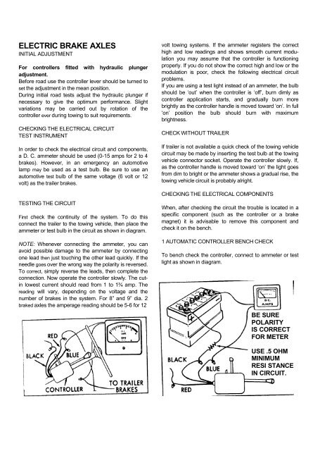
ELECTRIC BRAKE AXLESINITIAL ADJUSTMENTFor controllers fitted with hydraulic plungeradjustment.Before road use <strong>the</strong> controller lever should be turned toset <strong>the</strong> adjustment <strong>in</strong> <strong>the</strong> mean position.Dur<strong>in</strong>g <strong>in</strong>itial road tests adjust <strong>the</strong> hydraulic plunger ifnecessary to give <strong>the</strong> optimum performance. Slightvariations may be carried out by rotation of <strong>the</strong>controller ever dur<strong>in</strong>g tow<strong>in</strong>g to suit requirements.CHECKING THE ELECTRICAL CIRCUITTEST INSTRUMENTIn order to check <strong>the</strong> electrical circuit and components,a D. C. ammeter should be used (0-15 amps for 2 to 4brakes). However, <strong>in</strong> an emergency an automotivelamp may be used as a test bulb. Be sure to use anautomotive test bulb of <strong>the</strong> same voltage (6 volt or 12volt) as <strong>the</strong> trailer brakes.TESTING THE CIRCUITFirst check <strong>the</strong> cont<strong>in</strong>uity of <strong>the</strong> system. To do thisconnect <strong>the</strong> trailer to <strong>the</strong> tow<strong>in</strong>g vehicle, <strong>the</strong>n place <strong>the</strong>ammeter or test bulb <strong>in</strong> <strong>the</strong> circuit as shown <strong>in</strong> diagram.NOTE: Whenever connect<strong>in</strong>g <strong>the</strong> ammeter, you canavoid possible damage to <strong>the</strong> ammeter by connect<strong>in</strong>gone lead <strong>the</strong>n just touch<strong>in</strong>g <strong>the</strong> o<strong>the</strong>r lead quickly. If <strong>the</strong>needle goes over <strong>the</strong> wrong way <strong>the</strong> polarity is reversed.To correct, simply reverse <strong>the</strong> leads, <strong>the</strong>n complete <strong>the</strong>connection. Now operate <strong>the</strong> controller slowly. The cut<strong>in</strong>lowest current should read from 1 to 1Ö amp. Theread<strong>in</strong>g will vary, depend<strong>in</strong>g on <strong>the</strong> voltage and <strong>the</strong>number of brakes <strong>in</strong> <strong>the</strong> system. For 8” and 9” dia. 2braked axles <strong>the</strong> amperage read<strong>in</strong>g should be 5-6 for 12volt tow<strong>in</strong>g systems. If <strong>the</strong> ammeter registers <strong>the</strong> correcthigh and low read<strong>in</strong>gs and shows smooth current modulationyou may assume that <strong>the</strong> controller is function<strong>in</strong>gproperly. If you do not show <strong>the</strong> correct high and low or <strong>the</strong>modulation is poor, check <strong>the</strong> follow<strong>in</strong>g electrical circuitproblems.If you are us<strong>in</strong>g a test light <strong>in</strong>stead of an ammeter, <strong>the</strong> bulbshould be ‘out’ when <strong>the</strong> controller is ‘off’, burn dimly ascontroller application starts, and gradually burn morebrightly as <strong>the</strong> controller handle is moved toward ‘on’. In full‘on’ position <strong>the</strong> bulb should burn with maximumbrightness.CHECK WITHOUT TRAILERIf trailer is not available a quick check of <strong>the</strong> tow<strong>in</strong>g vehiclecircuit may be made by <strong>in</strong>sert<strong>in</strong>g <strong>the</strong> test bulb at <strong>the</strong> tow<strong>in</strong>gvehicle connector socket. Operate <strong>the</strong> controller slowly. If,as <strong>the</strong> controller handle is moved toward ‘on’ <strong>the</strong> light goesfrom dim to bright or <strong>the</strong> ammeter shows a gradual rise, <strong>the</strong>tow<strong>in</strong>g vehicle circuit is probably alright.CHECKING THE ELECTRICAL COMPONENTSWhen, after check<strong>in</strong>g <strong>the</strong> circuit <strong>the</strong> trouble is located <strong>in</strong> aspecific component (such as <strong>the</strong> controller or a brakemagnet) it is advisable to remove this component andcheck it on <strong>the</strong> bench.1 AUTOMATIC CONTROLLER BENCH CHECKTo bench check <strong>the</strong> controller, connect to ammeter or testlight as shown <strong>in</strong> diagram.BE SUREPOLARITYIS CORRECTFOR METERUSE .5 OHMMINIMUMRESI STANCEIN CIRCUIT.