

Interlocking - Alstom
Interlocking - Alstom
Interlocking - Alstom

Create successful ePaper yourself
Turn your PDF publications into a flip-book with our unique Google optimized e-Paper software.
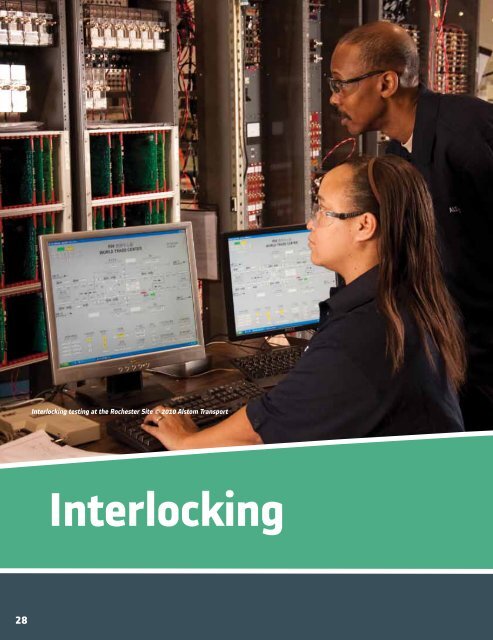
<strong>Interlocking</strong> testing at the Rochester Site © 2010 <strong>Alstom</strong> Transport<strong>Interlocking</strong>28
Signaling Ahead for Utah’sFrontRunner SouthA Unique Ability to BothDesign and Build HelpsKeep Costs DownDue to extreme traffic congestion and withpopulation steadily growing, Utah TransitAuthority (UTA) decided to expand itsFrontRunner commuter route by opening upa 45-mile extension. The new line will have8 new stations, which will run adjacent toexisting Union Pacific railroad track. This willbe a single track railroad with 19 interlockingsto accommodate passing sidings.<strong>Alstom</strong> was awarded this subcontract fromRail Systems Solutions. Over 85 wiredhouse locations will be supplied by <strong>Alstom</strong>to accommodate necessary controls for allinterlockings, track circuits and grade crossings.The system set up forms an integrated solutionutilizing industry standard components. Thecore of this integrated system is <strong>Alstom</strong>’sVital Microprocessor <strong>Interlocking</strong> andGenrakode electronic coded track circuitfamily of products.In This Section:iVPIVPI ®VPI ® II<strong>Interlocking</strong>s for thisproject are based upon<strong>Alstom</strong>’s iVPI product,the upgraded IntegratedVital Microprocessor<strong>Interlocking</strong> utilizinghigh speed Ethernetcommunications forvital serial links,communications to thecentral control office andremote diagnostics.This configurationoffered by <strong>Alstom</strong> willallow the commuterline to operate athigher speeds, reducelatency, and allowmaintenance andoperations personnel toaccess information fromremote locations.<strong>Alstom</strong>’s engineershave both defined thesystem requirements,and designed thesignaling system,allowing for astreamlined and costeffectiveproject.Note: The whole FrontRunner South line is scheduled to be completed in 2015.VPI ® / VPI II HardwareOrdering InformationApplication Tools29
iVPI Integrated Vital Processor <strong>Interlocking</strong><strong>Interlocking</strong>ALSTOM’s latest solution for processor basedinterlocking and wayside control, iVPI® is anincremental evolution of the service provenVital Processor <strong>Interlocking</strong>® (VPI®) system.First introduced in 2007, the iVPI version ofthe VPI family offers the newest upgrades inelectronics packaging and the latest in surfacemount technology (SMT).iVPI Systems maintain the usage of the sameVital hardware designs and Vital softwarealgorithms as the earlier generations of theVPI family. Like the previous generations ofthe VPI family, iVPI is functionally compatiblewith and is designed for long life cycle supportand upgrades.The “i” in <strong>Alstom</strong>’s iVPI vital processor interlocking stands for integrated, which represents the high degree of technologicalintegration this solution offers, resulting in space, costs and time savings.iVPI provides an integrated platform based on proven VPI technology for use with any size interlocking, from a single, remotelycontrolled switch machine at end of siding to a large interlocking plant.iVPI’s wide range of scalability and interconnectivity provides greater flexibility to deploy signaling components. This rangesfrom smaller room arrangements, to the use of small cases where larger rooms were once required, to the placing of the controlfunctions closer to the device being controlled thus minimizing cable costs. This new approach, made possible by reducing theform factor of the Vital and non-vital hardware and the use of network connectivity makes it possible to provide a “best fit”solution to all types of signaling applications. Despite the smaller form factor, the system is expandable to 320 vital inputs and320 vital outputs in one system; other solutions would require multiple systems to achieve the same number of vital inputs andoutputs.The One Solution for ALL Your <strong>Interlocking</strong> Needs30CALL 800.717.4477 • FAX 585.274.8777
iVPI Integrated Vital Processor <strong>Interlocking</strong>iVPI Modules> 21-slot main chassis – Includes integrated Power Supply> 21-slot expansion chassis - Includes integrated Power Supply> Dual 10-slot chassis – Two completely isolated systems in one chassis<strong>Interlocking</strong>iVPI 21-Slot Main ChassisiVPI BoardSpecificationsDataValueSignaling Power Supply9-12Vdc, 110Vac, 24/28Vdc, 50Vac/dcInternal Power Supply5Vdc (3000 Vdc Isolation from Sys Supply)Operating Temp-40 deg C to +70 deg CStorage Temp-55 C to +85 CHumidity0 to 95% Non CondensingVital Isolation (I/O and to Earth)3000 Breakdown VoltageTypical Weight15 lbs per ChassisChassis Size16H x 19W x 13D inchesMTBF (Demonstrated SYS)>100, 0000 Hours Depending on ConfigMTTR
iVPI Integrated Vital Processor <strong>Interlocking</strong><strong>Interlocking</strong>FEATURES and BenefitsThe main benefit offered by iVPI is the form of lower cost of system ownership addressing:> Scalability – easy to partition vital functions without carrying HW overhead> Connectivity – smaller control modules nodes that can share vital, non-vital, and diagnostics> Distributability/Partitioning – place control function where its needed to leverage bestengineering, maintenance, installation scenario> Availability/Maintainability – distributed control allows graceful degradation for <strong>Interlocking</strong>> Maintainability/Serviceability – all components accessible for diagnostics over network.Observe real-time logic, configuration, diagnostics, events locally or remote> GO/NO-GO indication for first line troubleshooting> Hardware configuration information from maintenance tools point to Lowest ReplaceableUnit (LRU)> Ease of Maintenance – training with less equipment and superior tools> Cable Savings – control functions placed closer to the device being controlled, smaller roomarrangements and use of small cases where larger rooms were once requirediVPI 21-Slot Module32CALL 800.717.4477 • FAX 585.274.8777
iVPI Integrated Vital Processor <strong>Interlocking</strong>The iVPI components provide feature, function upgrades in hardware, software and tools:> Hardware Configuration Control - Embedded printed circuit board identificationLinked to FRA Requirement (Rev, PN)> Direct Download of Software (No EPROM’s)> Support for both USB and traditional Serial Interface> Printed Circuit Boards Plug In Any Slot in Chassis<strong>Interlocking</strong>> Latest Surface Mount Design Technology> Ease of Connections (e.g. Wago type for <strong>Interlocking</strong>)> Health Indications (Go/No Go LED Per Printed Circuit Board)> Wall or rack mount ChassisFunction UpgradesHardwareCommon Hardware set serves many usesRemote I/O interfaces, <strong>Interlocking</strong> logic, vital communicationsImproved spares situationNetworked functions permits distributed computingSame components handle multifunction (e.g. VSP is <strong>Interlocking</strong> processor or a simple I/O controller, etc.) using same core design andusing application tool for configurationSoftwareSame Vital System Exec Software for all Levels of <strong>Interlocking</strong> ApplicationsElectronically Keyed Software Prohibits Incorrect Configurations, Revisions or VersionsReported by Maintenance Management System (MMS) ToolsAny of Industry Standard CTC or Related Protocols (Datatrain, Geniysis, Modbus, …)Collects and Reports Event Log Contained within the Non-vital processorToolsSame Tools Used For All Releases of VPI (CAAPE Based)Connect MMS Tool via Radio or Other Network connection to Witness Real Time InfoRepresentations of Logic in Relay, Ladder, Boolean Logic Formats (Change with Mouse “click”)©2011 <strong>Alstom</strong> Signaling Inc. www.alstomsignalingsolutions.com 33
iVPI Integrated Vital Processor <strong>Interlocking</strong><strong>Interlocking</strong>iVPI Vital Subsystem> Vital System Processor board (VSP) –Controls all aspects of the Vital subsystem,including all vital communications protocols.> Direct Input board (DI) – 16 vital inputsper board> Single Break Output board (SBO) – 8 vitaloutputs per board.> Double Break Output board (DBO) – 8 vitaloutputs per board.iVPI Non-Vital Subsystem> Non-Vital System Processor board(NVSP) – Controls all aspects of theNon-Vital subsystem, including all nonvitalcommunications protocols.> Non-Vital Input board (NVI) - 32 non-vitaloutputs per board, relay (form A & form C)of solid state.> Non-Vital Output board (NVO) - 32 non-vitalinputs per board.> Lamp Driver Output board (LDO) – 8 vitaloutputs per board, including filament proving.> AC Output board (ACO) – 8 vital outputs perboard, available with either 3mA threshold or65mA threshold.> Code Rate Generator board (CRG) – 8 vitaloutputs per board, each output can generateone of 10 coded cab signal output rates.> Genrakode Track Processor board (GTP) –Two Genrakode-style coded DC rack circuitinterfaces.> Bus Expansion board (BEX) – allowconnection of expansion chassis.iVPI VSP Board34CALL 800.717.4477 • FAX 585.274.8777
iVPI Integrated Vital Processor <strong>Interlocking</strong>Feature ComparisonFeature iVPI VPI II VPIScalable Application (up to three expansions chassis) √ √ √Application represented in Relay, Ladder, or Boolean format √ √ √Vital and non-vital systems within the same chassis √ √ √In-Circuit programming of System and Application Software (No EPROMS) √ √Network Connectivity for Vital system √ √Network Connectivity for Non-Vital system √ √Local and remote Diagnostics via Maintenance Management System (MMS) √ √Serial and USB user interface √ √Integrated Power Supply√Printed Circuit Board Health Indicator√Embedded Circuit Board Identification√Optional Integrated DC Coded Track Circuit√Universal Vital I/O boards (no board resident configuration)√Fully redundant systems within the same chassis√Number of vital system boards required 1 3 3<strong>Interlocking</strong>The iVPI control system consists of a:> Failsafe Vital System Processor (VSP) withintegrated Vital network communicationssupporting VSoE, other Vital protocols andthe <strong>Alstom</strong> Maintenance Management System(MMS).> Family of Failsafe Vital I/O to/from remotesignaling devices and Vital field apparatussuch as switch machines, train stops, trackcircuits, signal lamps and LED arrays,highway crossing equipment, cab signalingequipment, and more.> Where required by application, integratedGenrakode Track Processor (GTP) for directinterface at control points to the codedtrack circuits. Other integrated Track Circuitfunctions are possible.> Integrated Code Rate Generator (CRG) forgenerating the speed command pulses usedto modulate the carrier frequency (forexample, 60 Hz) for track circuits within theinterlocking plant and at the interlocking endof the approach track circuits.> Non-Vital System Processor (NVSP) withintegrated Ethernet TCP/IP, synchronousand asynchronous communication channelscapable of simultaneously supportingmultiple communication protocols and MMS.> Family of Non-vital I/O to interface withnon- vital signaling apparatus such as LocalControl Panels, Intrusion alarms, non-vitaltrain inspection equipment, and more.©2011 <strong>Alstom</strong> Signaling Inc. www.alstomsignalingsolutions.com 35
iVPI Ordering Information<strong>Interlocking</strong>Ordering Information - Sub Rack21-Slot, with P2 Motherboard and 12VDC Power Isolation Unit. Direct wired I/O.Ordering Number Description31038-823-02 Main Module31038-823-03 expansion 1 Module31038-823-04 expansion 2 Module31038-823-05 expansion 3 Module21-Slot, with Split 10 slot /10 slot P2 Motherboard and 12VDC Power Isolation Unit. Direct wired I/O.Ordering NumberDescription31038-833-01 Main Module, Two 12vdc Power Isolation Units21-Slot, with P2 Motherboard and 12VDC Filter Unit. Direct wired I/O.Ordering NumberDescription31038-835-01 Main Module31038-835-02 expansion 1 Module31038-835-03 expansion 2 ModuleOrdering Information - System Processor BoardsOrdering NumberDescription31166-427-01 Vital System Processor (VSP)31166-428-01 non-Vital System Processor (NVSP)Ordering Information - Vital Input/Output BoardsOrdering NumberDescription31166-429-01 direct Input (DI) 9-16Vdc, 16 Differential31166-429-03 direct Input (DI) 24-34Vdc, 16 Differential31166-430-01 Single Break Output (SBO), 9-30Vdc, 3 mA threshold, 8-Ports31166-431-01 lamp Drive Output (LDO), 9-18Vdc, 3.3 Amp, 65 mA threshold, 8-Ports31166-432-01 AC Output (ACO) 90-130Vac, 0.8 Amp, 65 mA threshold, 8-Ports31166-432-02 AC Output (ACO) 90-130Vac, 0.5 Amp, 3 mA threshold, 8-Ports31166-433-01 double Break Output (DBO) 9-16V, 0.6 Amp, 3 mA threshold 8-Ports31166-433-02 double Break Output (DBO) 18-34V, 0.3 Amp, 3 mA threshold 8-PortsFor assistance in ordering chassis and boards for your system or for assistance in selecting and configuring a new system oraddition please contact the <strong>Alstom</strong> Customer Service Center at 800-717-4477.36CALL 800.717.4477 • FAX 585.274.8777
iVPI Ordering InformationOrdering Information - Non-Vital Input/Output BoardsOrdering Number Description31166-457-01 non-Vital Input (NVI), In 18-36Vdc, 32-Differential Input31166-457-02 non-Vital Input (NVI), In 9-18Vdc, 32-Differential Input31166-458-01 non-Vital Output (NVO), RELAY, 16-Form A, 16-Form C, 0-35V AC/DC, 0.5 Amp31166-458-02 non-Vital Output (NVO), Solid State Relay, 32-SSR, 0-35V AC/DC, 0.25 AmpOrdering Information - Specialty Boards<strong>Interlocking</strong>Ordering NumberDescription31166-434-01 genrakode Track Processor (GTP), 2-Genrakode DC Track Circuits31166-459-01 Code Rate Generator (CRG), Code Rates: 0, 50, 75, 120, 180, 270, 420, Steady-On, Solid State Driver31166-459-02 Code Rate Generator (CRG), Code Rates: 0, 50, 75, 120, 180, 270, 420, Steady-On, Relay Driver31166-460-01 bus Expansion Board (BEX)Ordering Information - Interface Boards and CablesOrdering NumberDescription31166-472-01 VSP, P2, System ID (Site + Revision), 4-Switches 0-9, A-F31166-473-01 VSP, P3, MAC-Main, 2 Ethernet Ports RJ45, Health Monitor (Comm), VRD Connections31166-474-01 nVSP, P1, 2 Ethernet Ports RJ45 Connections31166-475-01 nVSP, P3, MAC-Main, Health Monitors (Main-Comm), three Serial Communications Ports31166-485-01 VSP P1 and BEX P3, Expansion Bus InterfaceOrdering Information - Development ToolsOrdering NumberDescription31754-008 Rev E Computer Aided Application Programming Environment (CAAPE) PackagiVPI NVSP BoardFor assistance in ordering chassis and boards for your system or for assistance in selecting and configuring a new system oraddition please contact the <strong>Alstom</strong> Customer Service Center at 800-717-4477.©2011 <strong>Alstom</strong> Signaling Inc. www.alstomsignalingsolutions.com 37
VPI ® Vital and Non-Vital <strong>Interlocking</strong> Control<strong>Interlocking</strong>> A Solution for All Sizes<strong>Alstom</strong> VPI <strong>Interlocking</strong> Control Systems have set the worldwide standardfor microprocessor-based interlocking control. From the smallest endof-sidingto large installations like Grand Central Terminal in New YorkCity, <strong>Alstom</strong>’s VPI system and microprocessor-based components usevital logic to allow customers to meet their needs for vital and non-vitalwayside control and communication.> A Strong Safety RecordThe microprocessor-based VPI <strong>Interlocking</strong> Control System has beenindependently audited for safety by the London Underground Limited,Dutch National Railway, CP Rail, Metro-North Commuter Railroad,Queensland Railroad (Australia), and Bay Area Rapid Transit (BART).Since the first installation in 1986 there have been no unsafe failures, anunblemished record of VPI Controlled Vital System Operation in excessof 90 million hours.> Easy InterfaceVPI surpasses relay-based systems as one unit can replace hundredsof relays. VPI resides in a significantly reduced space, provides serialcommunications that reduce the time and cost associated with cabling,and can be configured in a redundant arrangement. Customers caneasily interface VPI systems to other vital and non-vital waysideequipment, local control panels, and central office provided by <strong>Alstom</strong> orother suppliers. VPI system software includes extensive self-diagnosticcapability. Because of these built-in capabilities, most maintenance,troubleshooting and system testing tasks require only a simple terminalinterface such as a laptop or hand-held terminal to isolate the failureto a specific circuit board or input/output port. This makes testingsimple and straightforward. Test engineers also benefit from having todo limited retests of specific functions due to VPI’s ability to accuratelyidentify program revisions.> Enhanced VPIVPI has undergone several upgrades to the core hardware and softwareover the past 20 years to fulfill our customers demands and expectations.VPI II refers to recent key improvements made to the core portfoliothat allow for much more added functionality which are focused onperformance and maintainability. These enhancements address the fullcycle of interlocking control with improvements in design, verification,test functions and maintenance, which achieves a significant increase insystem performance.38CALL 800.717.4477 • FAX 585.274.8777
VPI ® Block DiagramMaintenanceManagement SystemDiagnosticWork Center<strong>Interlocking</strong>(Communication cable, wireless, or ethernet network)Ethernet©2011 <strong>Alstom</strong> Signaling Inc. www.alstomsignalingsolutions.com 39
VPI ® Vital and Non-Vital <strong>Interlocking</strong> Control<strong>Interlocking</strong>FEATURES> ProvenNo unsafe failures since the firstinstallation in 1986Total hours of VPI ControlledVital System Operation in excessof 72,000,000 hoursVPI Chassis and boards> ExpandableFrom end-of-siding, to interlockingswith up to 35 switch machines> FlexibleModular architectureForward and backward compatibility> Cost-EffectiveVPI will lower your system’s life cycle costs> Easy to MaintainSelf diagnostics make the system virtuallymaintenance-free> IntegratedHigh degree of subsystem integrationSpecifications - VPI ® Module (Chassis and Boards)DataValueLogic Input Power5 VDC (+ 0.25) at 8 Amperes max. per moduleHigh Voltage Isolation RatingMeets AREMA requirementsOperating Temperature -40° F to +160° F (-40° C to +70° C)Humidity0 to 95% Non-CondensingTypical Weight per module (with some boards)15 lbs. (6.80 kg)Dimensions 14” H x 19” W x 13” D (35.6 cm H x 48.3 cm W x 48.5 cm D)(Depth includes cable dress at rear chassis)For assistance in ordering chassis and boards for your system or for assistance in selecting and configuring a new system oraddition please contact the <strong>Alstom</strong> Customer Service Center at 1-800-717-4477.40CALL 800.717.4477 • FAX 585.274.8777
VPI ® II Vital and Non-Vital <strong>Interlocking</strong> ControlENHANCED FEATURES> System ArchitectureWith increased processing capacity and network connectivity,VPI II provides industry leading flexibility in interlockingapplication and partitioning. Options allow for distributed orcentralized traffic control through networked main processingand I/O and point of issue diagnosis for system faults. Moresystem wide control can be performed in a single systemto meet the demands of the application. This reduces theoverall number of systems required, and improves overallperformance as there are fewer systems exchanging timecritical interlocking control and status parameters.> System Condition MonitoringThe newest Maintenance Management System allows easyaccess to the system’s operational status, troubleshootingof failed components, and configuration management ofhardware and software. All “smart” system componentsthat pass information over the integrated network are readilyavailable to maintenance, engineering and/or dispatchcenters for tracking system operation.> Local or Centralized MMSSignificantly improves mean time to restore throughadvanced diagnostics, streamlined field tests, and utilitiesfor extensive site data management such as event logs andconfiguration information.> Upgraded Central ProcessorExtended capacity for larger interlockings which results indecreased train routing latencies.> Network CapabilityThe VPI II has a flexible system for partitioning throughefficient communication of signaling control, fault diagnosisand vital and non-vital health monitoring information.> LED Signal DriveUpgraded adjustment and monitoring features improvesetup and maintenance of LED Signal Aspects.<strong>Interlocking</strong>Feature ComparisonFeature VPI VPI IIScalable Application (up to three expansions chassis) √ √Application represented in Relay, Ladder, or Boolean format √ √Vital and non-vital systems within the same chassis √ √In-Circuit programming of System and Application Software (No EPROMS)√Network Connectivity for Vital system√Network Connectivity for Non-Vital system√Local and remote Diagnostics via Maintenance Management System (MMS)√Serial and USB user interface√Integrated Power SupplyPrinted Circuit Board Health IndicatorEmbedded Circuit Board IdentificationOptional Integrated DC Coded Track CircuitUniversal Vital I/O boards (no board resident configuration)Fully redundant systems within the same chassisNumber of vital system boards required 3 3©2011 <strong>Alstom</strong> Signaling Inc. www.alstomsignalingsolutions.com 41
VPI ® II Network Connectivity<strong>Interlocking</strong>VPI II network connectivity recognizes the current and future applications require flexible system partitioning and efficientcommunication of signal control, fault diagnosis and health monitoring (both vital and non-vital) information.VPI II’s on-board network capability can now utilize customer installed network systems and reduce dependencies ondedicated line and fiber circuits, reducing both the initial cabling expense as well as future related maintenance requirements.To meet the needs of Signal Engineers in providing application solutions for <strong>Interlocking</strong> and Train Control, <strong>Alstom</strong> has releasedthe next generation of VPI II with the following improvements:The following is a brief, high-level summary of the CPU II and CSEX4 modules that are the integralpieces of the VPI II system.> CPU II BoardThe CPU II is the vital system board for VPI II that incorporates vital logic processing, vital I/O control and monitoring,on-board programming, extended capacity for large interlocking controls and communications between same systems withinthe train control room and room to room. CPU II contains two microprocessors that separately perform the vital processingand the high-speed communications functions.The communication layer contains a network stack while the applications layer allows the Signal Engineer to develop theapplication logic for the interlocking or train control system. Combined with tools contained in the CAAPE package, the Signalengineer can read / download / upload the system software and application data structures to Flash PROMs. The separateprocessors minimize any impact to the vital system while communicating with other system boards with a similar networkinterface capability.VPI CPU II Board42CALL 800.717.4477 • FAX 585.274.8777
VPI ® II Network Connectivity> CSEX4 BoardThe CSEX4 board has two Ethernet communication channelsand four serial ports (three ports which are programmable, oneport is always the MAC – Maintenance ACcess) available witheach serial port being capable of operating up to 57.6KBPS.This board is designed such that it can also be interfaceddirectly to standard communication equipment such as FiberOptic Modems, Multiplexers, and Network Adapters. The CSEX4board can be application programmed with non-vital logic toperform man-machine interfaces, to perform, entrance-exitlogic and a multitude of other non-vital functions. The board canbe used to interface with communications bases Local ControlPanel and/or computers; or using the nonvital I/O boards it candirectly interface to discrete wired Local Control Panels.The CSEX4 board also contains a battery backed-upmemory section and clock/calendar to support the onboardDATALOGGER software used for logging both vital and nonvitalvariables. Three of the communication ports in additionto the two Ethernet ports can be utilized for external non-vitalcommunications. Each port may be configured with the sameor with a different communication protocol. The choice ofprotocols is assigned and configured in the Computer AidedApplication tools by the signal engineer. A library of almostforty communication protocols common to the railroad andtransit industry is included in the Computer Aided Applicationpackage. Typical protocols included are industry standards suchas GENISYS, Data Train, MODBUS and MCS among others.<strong>Interlocking</strong>CSEX4 Supported ProtocolsManualCompany Name/Protocol DescriptionP2346AAlgemene Sein Industrie B.V., ASI by Netherlands Spoorwegen (NS) / Lokale Controle Eenheid (LCE)P2346Bwestinghouse Brake & Signal / S2P2346DALSTOM / GRS DataTrain IVP2346EALSTOM / GRS DataTrain VIIIP2346FUnion Switch & Signal / GenisysP2346HSafetran / SCS128P2346LDTSlg Industrial Systems / LDTSP2346MModicon / Modbus RTUP2346NALSTOM / GRS DataTrain IIP2346QCanadian National RR / CN2000P2346Rge/Harmon / MCS1P2346Tbailey / S9600P2346U Advanced Train Control System Wayside Interface Unit, Specification 3 & 4P2346XHanning & Kahl / HCS-R radio control route equipmentP2346YALSTOM Signal Netherlands for PRORAIL / OPCENoneASCII©2011 <strong>Alstom</strong> Signaling Inc. www.alstomsignalingsolutions.com 43
VPI ® II Lamp Driver Output Board (LDO2)<strong>Interlocking</strong>LDO2 (LAMP DRIVER OUTPUT) BOARDThe Lamp Driver Output Board is a vital output board used to provide power to signals for both transit and railroadapplications. Using the same proven vital techniques found on other VPI vital output boards, the new LDO2 includes thefollowing features:> Current Monitoring - reads the current through the output every 200 milliseconds. This current can be compared to oneof eight different threshold levels from 0.0 to 3.25 Amps, which will turn the output off if it is not drawing the minimumrequired current. The filament checking routines enables down grading and prevents against overcurrent and shortprotection.> Cable Integrity Check - uses isolated voltage sensing at the output to determine if a potential exists across the outputwhen the output is off. A separate switch for each output can be used to select the system reaction to this event bylogging the error or dropping a vital relay.> Diagnostic Interface to VPI CPU II Board - registers all current readings and error conditions and can be read or clearedvia the CPU II board.> Board Edge User Interface - registers all current readings and error conditions and can be read or cleared alternatively viathe Board Edge User Interface.VPI LDO2 Board44CALL 800.717.4477 • FAX 585.274.8777
VPI ® / VPI II Hardware<strong>Alstom</strong> can customize the VPI to many specific requirements. Different hardware configurations can be designed with oneprocessor controlling up to 35 switch machines, related track circuits and signals. This is accomplished through the availabilityof up to 320 vital inputs and 320 vital outputs, 640 non-vital I/O ports and vital and non-vital communication interfaces. TheVPI module has 21 slots for circuit boards and it mounts in a standard 19-inch rack. A single VPI system may be comprised ofmore than one module, depending on the amount of vital I/O and system logic that is required.The module is designed to be flexible and expandable. Printed circuit boards may be located in a variety of slots, dependingon your requirements. Additional expansion modules are interconnected by ribbon cables. Input/output cables are connecteddirectly to edge connectors on the boards to minimize cable connections. Optional configurations are available using standardAMP Type M connectors mounted on the rear panel (28-way connectors for vital functions, 50-way or 75-way for non-vitalfunctions), direct wire interfaces or backplane cards with Cage-Clamp style connectors.<strong>Interlocking</strong>FEATURESCircuit Modules> CPU Polynomial DivderAll vital application logic is storedon this board and executed from it.Performs calculations necessary forevaluating expressions and verifyingthe system program, guaranteeingproper system operation.> Vital Relay DriverReceives system information,vitally processes it and, if correct,provides output to vital disconnect relay.> Vital Serial ControllerCommunicates vital information betweenVPI systems via serial transmission link,no line wires needed.Incorporates full duplex communicationup to 19,200 bps, with Manchesterencoding and extended CRC check toensure data integrity.> Input/Output InterfaceProvides proper interface to vital inputsand outputs.> VPI Supervisory Communicationsand Control SubsystemExtended code system emulatorperforms non-vital applications functions.©2011 <strong>Alstom</strong> Signaling Inc. www.alstomsignalingsolutions.com 45
VPI ® / VPI II Hardware<strong>Interlocking</strong>Chassis Configurations> Plug Coupled ChassisThe VPI II plug coupled chassis includes internalcable harness assemblies. These assembliesconnect the VPI II PCB I/O point(s) to a series ofAMP type M-series plug couplers, mounted on therear panel of the chassis. The rear panel alsocontains a 14-pin type M-series plug coupler for the5 VDC power connection and provisions for up tofour 60-way ribbon cable connectors for connectingto expansion chassis.Plug Coupled Chassis> Direct Wire ChassisThe direct wire chassis is configured to allow the I/Owiring to be economical by directly inserting wire intothe PCB edge connectors in the chassis. This chassisconfiguration does not allow for quick removal of thechassis from a wired rack. However, all the PCBscan be removed and no active electronic componentsare left in the chassis. This version is intendedfor applications where the rack housing this chassisprovides a plugcoupled connection to the otherinterlocking equipment.Direct Wire ChassisCPIB Chassis> Control Point in a Box (CPIB) ChassisThe CPIB interface chassis uses Back PlaneInterface Cards (BPIC) with Cage-Clamp style(spring cage clamp) wire termination blocks andprinted circuit board edge connectors to map theI/O termination points on the VPI II PCBs to discretewire connectors. The chassis is designed to allowthese interface PCBs to be inserted and removedfrom the rear of the chassis. This provides a wiretermination method that can be quickly disconnected(by removing the printed circuit boards) andindividual I/O points may be disconnected fortroubleshooting. This chassis style is intendedfor low density applications.46CALL 800.717.4477 • FAX 585.274.8777
VPI ® / VPI II Ordering InformationOrdering Information - Vital Direct InputOrdering NumberDescription59473-867-01 dI Board, 16 discrete inputs with filtering (9-15 VDC)59473-867-02 dI Board, 16 discrete inputs w/o filtering (9-15 VDC)59473-867-03 dI Board, 16 discrete inputs with hold circuit (9-15 VDC)59473-867-04 dI Board, 16 discrete inputs with filtering (45-55 VDC)59473-867-05 dI Board, 16 discrete inputs with filtering (9-22 VDC)59473-867-07 dI Board, 16 discrete inputs with filtering (24-34 VDC)59473-871-01 to 59473-871-16 Signature Header (A – P) respective (Grps 01 – 16) one for each board in system,determined by CAAPE<strong>Interlocking</strong>Ordering Information - Vital OutputOrdering NumberDescriptionLamp Driver Output59473-749-02 ldO Board, 8 outputs (9-18 VDC, 2.9 Amp operation, 100mA Threshold)59473-749-03 ldO Board, 8 outputs (15-30 VDC, 2.9 Amp operation, 100mA Threshold)59473-749-04 ldO Board, 8 outputs w/o Cold Check (9-18 VDC, 2.9 Amp operation, 100mA Threshold)31166-340-01 ldO2 Board, 8 outputs (9-18 VDC, 3.3 Amp operation, 100mA Threshold)31166-340-02 ldO2 Board, 8 outputs w/o current monitor, (9-18 VDC, 3.3 Amp operation, 100mA Threshold)Single Break Output59473-739-01 SBO Board, 8 outputs, Supply 9-30 VDC, Output = [Supply - typical 1 VDC],0.5 Amp, 3mA Threshold59473-739-02 SBO Board, 8 outputs, Supply 9-30 VDC, Output = [Supply - typical 1 VDC],0.5 Amp, 3mA Threshold, with code energy switchingDouble Break Output59473-747-02 dbO Board, 8 outputs, Supply 9-15 VDC, 2 x Output = [2*Supply - (5*outAmp)],0.3 Amp operation, 3mA Threshold59473-747-03 dbO Board, 8 outputs, Supply 9-15 VDC, Output = [Supply - (5*outAmp)],0.6 Amp operation, 3mA Threshold, different keying as Group 02 board59473-977-01 dbO Board, 8 outputs, Supply 30-40 VDC, Out 50 VDC, 140 mA operation, 3mA Threshold59473-977-02 dbO Board, 8 outputs, Supply 45-55 VDC, Out 50 VDC, 140 mA operation, 3mA ThresholdAC Output59473-937-02 ACO Board, 8 outputs (90-130 VAC, 40-150Hz, 0.8 Amp operation, 100mA Threshold)w/enhanced EMI protection59473-937-03 ACO Board, 8 outputs (90-130 VAC, 40-150Hz, 0.5 Amp operation, 5mA Threshold)Board Signature Device39780-003-01 to 39780-003-40 Signature PROM, one for each output board in a system, determined by CAAPE31166-304-01 Selectable Signature PROM, Could be used in place of PROMs 39780-003-01 to 39780-003-40Ordering Information - Vital Code Rate GeneratorOrdering NumberDescription31166-261-03 CRG Board for solid state code followers; produces codes of 0, 50, 75, 120, 180pulses per minute and Steady On31166-261-04 CRG Board for vital relay code followers; produces codes of 0, 50, 75, 120, 180,270, 420 pulses per minute and Steady OnFor assistance in ordering chassis and boards for your system or for assistance in selecting and configuring a new system oraddition please contact the <strong>Alstom</strong> Customer Service Center at 800-717-4477.©2011 <strong>Alstom</strong> Signaling Inc. www.alstomsignalingsolutions.com 47
VPI ® / VPI ® II Ordering Information<strong>Interlocking</strong>Ordering Information - Vital TimerFeature> Provides up to 8 field-settable vital time delays per board, up to 16 timers per system.Ordering NumberDescription59473-894-01 fSVT Board, 8 timers (0 – 59:59 sec) for timers one through eight59473-894-02 fSVT Board, 8 timers (0 – 59:59 sec) for timers nine through sixteenOrdering Information - Non-Vital Code System Emulator ExtendedFeature> Extended code system emulator; emulates electronic or relay-based code system and also performs non-vitalapplication functions and data logging. Typical functions include local control panel interface and N/X logic.Ordering NumberDescription31166-175-02 CSEX3 Board, 5 communication interfaces, includes blank EE PROMs31166-175-03 CSEX3 Board, 4 communication interfaces, + 1 DC code, includes blank EE PROMs31166-417-01 CSEX4 Board, 386 processor, 3 comm ports, 2 Ethernet01169-767-OnSystem/Application EEPROMs (PLCC 29F040 FLASH, 2/brd)Ordering Information - Non-Vital InputOrdering NumberDescription59473-757-02 nVI Board, 32 high-true inputs (18-33 VDC)59473-757-03 nVI Board, 32 high-true inputs (9-18 VDC)31166-276-01 nVID Board, 32 differential inputs, (9-18 VDC) w/switches to force each input on/off31166-276-02 nVID Board, 32 differential inputs, (9-18 VDC) no switches31166-276-03 nVID Board, 32 differential inputs, (18-33 VDC) w/switches to force each input on/off31166-276-04 nVID Board, 32 differential inputs (18-33 VDC) no switchesOrdering Information - Non-Vital OutputOrdering NumberDescriptionDC Output, source or (+) output59473-785-01 nVO Board, (18-33 VDC, 250 mA operation)59473-785-02 nVO Board, (9-18 VDC, 250 mA operation)59473-785-03 nVO Board, (18-33 VDC, 250 mA operation) w/Power On Reset59473-785-04 nVO Board, (9-18 VDC, 250 mA operation) w/Power On Reset59473-785-05 nVO Board, (4.5-14.5 VDC, 250 mA operation) w/Power On ResetDC Output, sink or (-) output31166-123-01 nVO-SNK Board, (4.5-5.5 VDC, 250 mA operation) w/Power On ResetRelay Output31166-238-01 nVR Board, (0-35 V AC or DC , 1 Amp operation) w/Power On Reset, coil supplyfrom 9-18 VDC31166-238-02 nVR Board, (0-35 V AC or DC, 1 Amp operation) w/Power On Reset, coil supplyfrom 18-35 VDCAC Output59473-936-01 nVOAC Board, (5-250 VDC, 250 mA operation)59473-936-02 nVOAC Board, (5-250 VDC, 250 mA operation) w/Power On Reset48For assistance in ordering chassis and boards for your system or for assistance in selecting and configuring a new system oraddition please contact the <strong>Alstom</strong> Customer Service Center at 800-717-4477.CALL 800.717.4477 • FAX 585.274.8777
VPI ® / VPI ® II Ordering InformationOrdering Information - Non-Vital Train to Wayside CommunicationOrdering Number DescriptionVPI Chassis Plug-In Boards31166-099-02 nVTWC-MOD Board, 2-channel TWC for BART31166-100-02 nVTWC-MUX Board, Processor Multiplexer for BART31166-119-02 nVTWC-FSK Board, 4 channel TWC for MARTA31166-119-03 nVTWC-FSK Board, 4 channel TWC for Shanghai, Taipei, Taegu31166-119-04 nVTWC-FSK Board, 4 channel TWC for WMATA31166-119-05 nVTWC-FSK Board, 4 channel TWC for Seoul Metro Line 631166-119-06 nVTWC-FSK Board, 4 channel TWCInterface Plates and Cases42560-303-01 b2 Plate, TWC track connection interface for BART43920-076-01 nVTWC coupling case for BART42560-302-01 b1 Plate, TWC track connection interface for MARTA42560-307-01 b2 Plate, TWC track connection/ATP interface for Shanghai, Taipei, Taegu42560-307-03 b2 Plate, TWC track connection/ATP interface for WMATA42560-316-01 b2 Plate, TWC track connection/ATP interface for Seoul Metro Line 642560-317-01 nVTWC coupling case filter for Seoul Metro Line 6<strong>Interlocking</strong>Ordering Information - VPI ChassisOrdering NumberDescriptionPlug Coupler Chassis31506-015-01 21-slot w/divided motherboard slots 5/16 and plug coupler panel(specify bus and I/O cable harness separately)31506-015-11 21-slot w/plug coupler panel (specify bus and I/O cable harness separately)31506-015-15 21-slot-deep, w/divided motherboard slots 5/16 and plug coupler panel (specifybus and I/O cable harness separately)31506-015-16 21-slot-deep w/plug coupler panel (specify bus and I/O cable harness separately)31506-016-01 21-slot w/divided motherboard slots 5/16 and plug coupler panel(specify bus and I/O cable harness separately) - specialDirect Wired Chassis31506-015-02 21-slot w/divided motherboard slots 5/16, only bus extension panel(specify bus cables separately)31506-015-12 21-slot, only bus extension panel (specify bus cables separately)31506-015-03 21-slot w/divided motherboard slots 5/16, no cable panels31506-015-13 21-slot, no cable panels31506-015-14 21-slot w/divided motherboard slots 5/16, only bus extension panel(specify bus cables separately) - specialFor assistance in ordering chassis and boards for your system or for assistance in selecting and configuring a new system oraddition please contact the <strong>Alstom</strong> Customer Service Center at 800-717-4477.©2011 <strong>Alstom</strong> Signaling Inc. www.alstomsignalingsolutions.com 49
VPI ® / VPI ® II Ordering Information<strong>Interlocking</strong>Ordering Information - VPI Back Plane Interface Card for CPIB ChassisOrdering Number Description31166-194-01 bPIC Vital Output (SBO, DBO, ACO, LDO, LDO2, CRG)31166-195-01 bPIC Vital Direct Input (DI)31166-196-01 bPIC Nonvital I/O (NVI, NVO)31166-197-01 bPIC VRD and Module Power Interface (VRD)31166-198-01 bPIC Vital Serial Communication (VSC)31166-199-01 bPIC Non-vital Communication (CSEX3)31166-336-01 bPIC Vital Processor (CPU/PD, CPU2 w/o Communication Processor)bPIC, (CRG)Ordering Information - DC to DC Power ConvertorFeature> Provides the 5-volt VPI logic power> Provides Ordering the 12-volt Number VRD and DBO power Description if source is above 15 VDCOrdering NumberDescription42560-287-03 b2 Plate, In 8-35 VDC, Out 5.1 VDC, 20 Amp, CageClamp Terminals42560-287-05 b2 Plate, In 8-35 VDC, Out 5.1 VDC, 8 Amp, CageClamp Terminal42560-287-09 b2 Plate, In 8-35 VDC, Out 12 VDC, 4 Amp, CageClamp Terminals42560-287-10 b2 Plate, In 8-35 VDC, Out 12 VDC, 10 Amp, CageClamp TerminalsOrdering Information - Local Control PanelFeatures> Wide input power voltage range (9-33V DC)> Key Switch to request local control mode with Local Control indicator> Lamps ON/OFF and Lamp Test buttons> 24 push buttons with 24 LED indicators, backlighting the push buttons> Eight Non-Vital Outputs, relay contacts, 0.5 Amp DC or AC> Eight Non-Vital Inputs, 9-18 VDC> RS485 communications portOrdering NumberDescription42560-315-02 b5 Plate, 24 lighted pushbuttons, 8 non-vital inputs, 8 Form A Relay Outputs,and serial communication to CSEX BoardFor assistance in ordering chassis and boards for your system or for assistance in selecting and configuring a new system oraddition please contact the <strong>Alstom</strong> Customer Service Center at 800-717-4477.50CALL 800.717.4477 • FAX 585.274.8777
VPI ® / iVPI ToolsComputer Aided Application Programming Environment (CAAPE)<strong>Interlocking</strong>The VPI ® / iVPI Computer-Aided Application ProgrammingEnvironment (CAAPE) is a comprehensive set of developmenttools for creating vital and non-vital applications. These toolsare integrated together within a development environmentfor easy access and include graphical application buildingutilities, compilers for VPI ® /iVPI vital and non-vitalapplications, vital Application Data Verifier (ADV) and aGraphical Simulator. It provides for graphical hardwareconfiguration, relay or ladder logic program definition andcommunication assignments. It also allows for the printingof the graphical relay circuits for final documentation. Thebuild utilities include a library editor to create and maintaincommonly used logic routines for easy reuse.CAAPE includes an Application Data Verifier (ADV), which isan inverse compiler that checks the hardware configurationsand interlocking logic as resident within memory devicesto be installed in VPI ® /iVPI field equipment, and verifiesthat the data matches the intended user input. It producesdocumentation that tracks and highlights differences inan interlocking following changes to interlocking logic orconfiguration, thereby reducing the retest cycle.The Graphical Simulator consists of tools to generate controland indication panels and simulators to exercise the vitaland non-vital logic. The logic equations and variables canbe viewed graphically with the corresponding states duringsimulation run-time. Multiple VPI ® /iVPI systems can besimulated simultaneously.©2011 <strong>Alstom</strong> Signaling Inc. www.alstomsignalingsolutions.com 51
VPI ® / iVPI Tools<strong>Interlocking</strong>Computer Aided Application Programming Environment (CAAPE)FeaturesCAAPEGraphical Simulator> Graphical or Textual Application Generation > Decrease Factory and Field Testing> Integrated Application Design,Compiling, Simulation, Verificationand Configuration Management> Utilities for Printing GraphicalApplication Logic and Verifying FileCRC’s and ChecksumsADV> Reconstructs Application Designfrom EPROM> Generates Reports for Circuit Check> Validates Configuration Management> Simulate VPI ® / iVPI Systems to TestApplication Logic Without Hardware> Simulate Multiple iVPI Applicationsand Systems Simultaneously> Use Track Plan Display to SimulateOperation of Field Devices> View Status of Application Logic inGraphical Format, Set Breakpointsand Change-points to Stop Simulationat Specific Points in the Logic> Monitor and Record the States ofSelected Equations> Helps Verify that ApplicationPROM Data Matches the Intended User Input> Reduces Field Test TimeOrdering InformationSystem RequirementsList PricePC Running Windows 95, 98, NT 4.0, SP2 or later, 2000, or XP $7,500.00200 MB Available Hard Drive Space64 MB of RAM AvailableFor assistance in ordering any of the VPI ® / iVPI Tools for your system or for assistance in selecting and configuring a newsystem or addition, please contact the <strong>Alstom</strong> Customer Service Center at 800-717-4477.52CALL 800.717.4477 • FAX 585.274.8777
VPI ® / iVPI ToolsMaintenance Management System (MMS)Features> On-Screen Control and IndicationPanel is User Configurable forSmall to Large Applications> Graphical Diagnostics with VPI ® / iVPIModule View decrease systemdowntime and ease maintenance<strong>Interlocking</strong>> Remote or Local Diagnostic> Recording and Playback ofall Time-Stamped Status, Diagnosticand Event data - data logging views,real time troubleshooting help withcorrective action step> Verifies the installed harware andsoftware components> Built-In Configuration Management forVPI ® / iVPI System Validation> Watch application parameters andlogic while systems are runningThe Maintenance Management System (MMS)provides a singlegraphical framework for total system exploration of VPI ® / iVPIincluding full local control panel capabilities, diagnostics monitoringwith online help, vital and nonvital application logic troubleshootingand testing and interlocking maintenance scheduling. MMS is apersonal or laptop computer based user-friendly interactive program,which may be installed within an interlocking rack of equipment orkept portable.This supports field installation, test maintenance, preventative maintenance and condition monitoring of field devices.MMS can be configured as a single access point to multiple VPI ® / iVPI systems.MMS consists of the MMS editor and runtime programs. An MMS project is created using the MMS editor that importsapplication files from CAAPE. (See page 51 for details on CAAPE package.)Ordering InformationSystem RequirementsList PricePC Running Windows NT 4.0, SP6 or later, 2000 $5,000.005 GB Available Hard Drive Space128 MB of RAM Minimum©2011 <strong>Alstom</strong> Signaling Inc. www.alstomsignalingsolutions.com 53


