


You also want an ePaper? Increase the reach of your titles
YUMPU automatically turns print PDFs into web optimized ePapers that Google loves.
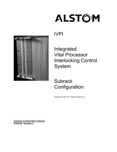
<strong>iVPI</strong>IntegratedVital ProcessorInterlocking ControlSystem<strong>Subrack</strong>ConfigurationCopyright © 2008, 2011 <strong>Alstom</strong> Signaling Inc.<strong>Subrack</strong> Configuration ManualP2521B, Volume 2
<strong>iVPI</strong>IntegratedVital ProcessorInterlocking ControlSystem<strong>Subrack</strong>ConfigurationCopyright © 2008, 2011 <strong>Alstom</strong> Signaling Inc.<strong>Subrack</strong> Configuration Manual<strong>Alstom</strong> Signaling Inc.P2521B, Volume 2, Rev. 2, February 2011, Printed in U.S.A.
LIST OF EFFECTIVE PAGESP2521B, Volume 2, <strong>iVPI</strong> Integrated Vital Processor Interlocking Control System<strong>Subrack</strong> Configuration ManualORIGINAL ISSUE DATE: October 2008CURRENT REVISION AND DATE:Rev. 2, February 2011, updated withcommercialized componentsPAGECoverTitle pagePrefacei thru iiCHANGE OR REVISION LEVELFeb/11Feb/11Feb/11Feb/111–1 thru 1–10 Feb/112–1 thru 2–2 Feb/113–1 thru 3–6 Feb/114–1 thru 4–4 Feb/11P2521B, Volume 2, Rev. 2, Feb/11<strong>Alstom</strong> Signaling Inc.
THIS PAGE INTENTIONALLY LEFT BLANK.P2521B, Volume 2, Rev. 2, Feb/11<strong>Alstom</strong> Signaling Inc.
PREFACENOTICE OF CONFIDENTIAL INFORMATIONInformation contained herein is confidential and is the property of <strong>Alstom</strong>Signaling Incorporated. Where furnished with a proposal, the recipientshall use it solely to evaluate the proposal. Where furnished to customer, itshall be used solely for the purposes of inspection, installation ormaintenance. Where furnished to a supplier, it shall be used solely in theperformance of the contract. The information shall not be used ordisclosed by the recipient for any other purposes whatsoever.FOR QUESTIONS AND INQUIRIES, CONTACT CUSTOMER SERVICE AT1-800-717-4477ORWWW.ALSTOMSIGNALINGSOLUTIONS.COMALSTOM SIGNALING INC.1025 JOHN STREETWEST HENRIETTA, NY 14586REVISION LOGRevision Date Description By Checked Approved1 October 2008 Original issue MAS RIH NI2 February2011Updated withcommercializedcomponentsMAS RIH NIP2521B, Volume 2, Rev. 2, Feb/11<strong>Alstom</strong> Signaling Inc.
THIS PAGE INTENTIONALLY LEFT BLANK.P2521B, Volume 2, Rev. 2, Feb/11<strong>Alstom</strong> Signaling Inc.
ABOUT THE MANUALThis manual is intended to describe the <strong>Alstom</strong> Integrated Vital Processor InterlockingControl System, (<strong>iVPI</strong>) <strong>Subrack</strong> configuration, including part numbers and <strong>Subrack</strong>illustrations. This manual is part of a 5 volume set of manuals. The set is summarized inSection 1.The information in this manual is arranged into sections. The title and a brief descriptionof each section follow:Section 1 – SYSTEM SUBRACK: This section provides an overview of <strong>iVPI</strong> System<strong>Subrack</strong> related options including part numbers and a brief explanation of theirapplication.Section 2 – CIRCUIT BOARD KEYING: This section provides the keying informationfor the circuit boards used in the <strong>iVPI</strong> System.Section 3 – SUBRACK HARDWARE: This section provides examples of <strong>iVPI</strong> <strong>Subrack</strong>hardware.Section 4 – SPECIAL TOOLS: This section shows the <strong>iVPI</strong> wiring and B-Relay tools.P2521B, Volume 2, Rev. 2, Feb/11<strong>Alstom</strong> Signaling Inc.
THIS PAGE INTENTIONALLY LEFT BLANK.P2521B, Volume 2, Rev. 2, Feb/11<strong>Alstom</strong> Signaling Inc.
MANUAL SPECIAL NOTATIONSIn the <strong>Alstom</strong> manuals, there are three methods used to convey special informationalnotations to the reader. These notations are warnings, cautions, and notes. Bothwarnings and cautions are readily noticeable by boldface type two lines beneath thecaption.WarningA warning is the most important notation to heed. A warning is used to tell the readerthat special attention needs to be paid to the message because if the instructions oradvice is not followed when working on the equipment then the result could be eitherserious harm or death. The sudden, unexpected operation of a switch machine, forexample, or the technician contacting the third rail could lead to personal injury or death.An example of a typical warning notice follows:CautionWARNINGDISCONNECT MOTOR ENERGY WHENEVER WORKING ON SWITCHLAYOUT OR SWITCH MACHINE. UNEXPECTED OPERATION OFMACHINE COULD CAUSE INJURY FROM OPEN GEARS, ELECTRICALSHOCK, OR MOVING SWITCH POINTS.A caution statement is used when an operating or maintenance procedure, practice,condition, or statement, which if not strictly adhered to, could result in damage to ordestruction of equipment. A typical caution found in a manual is as follows:NoteCAUTIONTurn power off before attempting to remove or insert circuit boards into a<strong>Subrack</strong>. Boards can be damaged if power is not turned off.A note is normally used to provide minor additional information to the reader to explainthe reason for a given step in a test procedure or to just provide a background detail. Anexample of the use of a note follows:NOTEA capacitor may be mounted on the circuit board with a RTV adhesive.Use the same color RTV.P2521B, Volume 2, Rev. 2, Feb/11<strong>Alstom</strong> Signaling Inc.
THIS PAGE INTENTIONALLY LEFT BLANK.P2521B, Volume 2, Rev. 2, Feb/11<strong>Alstom</strong> Signaling Inc.
TopicTABLE OF CONTENTSPage1. SECTION 1 – SYSTEM SUBRACK ...................................................................... 1–11.1. GENERAL ........................................................................................................ 1–11.2. MANUAL SET ORGANIZATION ...................................................................... 1–11.3. SUBRACK TERMS........................................................................................... 1–21.4. SUBRACK CONFIGURATION ......................................................................... 1–31.5. SUBRACK WIRING.......................................................................................... 1–61.5.1. Direct Wire........................................................................................................ 1–61.5.2. Connector Wiring.............................................................................................. 1–61.6. MOTHERBOARD ............................................................................................. 1–71.7. POWER ISOLATION UNIT............................................................................... 1–81.8. SUBRACK INTERFACE BOARDS................................................................. 1–102. SECTION 2 – CIRCUIT BOARD KEYING............................................................. 2–12.1. GENERAL ........................................................................................................ 2–12.2. INTRODUCTION .............................................................................................. 2–13. SECTION 3 – SUBRACK HARDWARE................................................................ 3–13.1. GENERAL ........................................................................................................ 3–13.2. INTRODUCTION .............................................................................................. 3–14. SECTION 4 – SPECIAL TOOLS ........................................................................... 4–14.1. GENERAL ........................................................................................................ 4–14.2. INTRODUCTION .............................................................................................. 4–1P2521B, Volume 2, Rev. 2, Feb/11 i <strong>Alstom</strong> Signaling Inc.
DescriptionLIST OF FIGURESPageFigure 1–1. <strong>iVPI</strong> Rack and <strong>Subrack</strong> ............................................................................ 1–2Figure 1–2. 21-Slot <strong>iVPI</strong> <strong>Subrack</strong> Populated with Boards (a System) ......................... 1–3Figure 1–3. Dual 10-Slot <strong>iVPI</strong> <strong>Subrack</strong> Populated with Boards (a System)................. 1–4Figure 1–4. Power Isolation Unit ................................................................................. 1–9Figure 2–1. Registration Keying Positions on Circuit Board ........................................ 2–1Figure 3–1. 21-slot <strong>Subrack</strong> (Empty <strong>iVPI</strong> Chassis with Motherboard)......................... 3–1Figure 3–2. Example Board Placement for Single 21-slot <strong>Subrack</strong> <strong>iVPI</strong> System ........ 3–2Figure 3–3. Dual 10-slot <strong>Subrack</strong> (Empty <strong>iVPI</strong> Chassis with Motherboards)............... 3–3Figure 3–4. Example Board Placement for Dual 10-slot <strong>Subrack</strong> <strong>iVPI</strong> System ........... 3–4Figure 3–5. B-Relay, B1 Neutral, Regular Release, 100 Ohm (Used with VRDBoard), P/N 56001-787-05 ....................................................................... 3–5Figure 4–1. Crimp Tool, B-Relay Crimp Terminals, P/N 24745-148-00....................... 4–2Figure 4–2. Crimp Tool, DIN Type F, P/N 24745-166-00, 24745-167-00,24745-168-00, 24745-169-00................................................................... 4–3Figure 4–3. Spanner Wrench for B-Relay 3E Post...................................................... 4–3Figure 4–4. PLCC 32 Pin IC Terminal Extraction Tool ................................................ 4–4Figure 4–5. Terminal Extraction Tool, B Relay Terminal, P/N 59688-000-00.............. 4–4Figure 4–6. Terminal Extraction Tool, DIN Type F, P/N 59688-038-00....................... 4–4DescriptionLIST OF TABLESPageTable 1–1. <strong>Subrack</strong> Part Numbers .............................................................................. 1–5Table 1–2. Power Isolation Unit Connections.............................................................. 1–8Table 2–1. Vital and Non-Vital PC Board Keying ........................................................ 2–2Table 4–1. Special Tools............................................................................................. 4–1P2521B, Volume 2, Rev. 2, Feb/11 ii <strong>Alstom</strong> Signaling Inc.
System <strong>Subrack</strong>1. SECTION 1 – SYSTEM SUBRACK1.1. GENERALThis manual provides an overview of <strong>Subrack</strong> related options including part numbersand a brief explanation of their application. Be aware that the <strong>Subrack</strong> configurationsprovided are examples only, refer to the location Book Of Plans (BOP) to determine thecomponents used in the site configuration. Note that all part numbers are <strong>Alstom</strong>numbers unless otherwise noted.See P2521B, Volume 1 for capacity overview and hardware criteria.1.2. MANUAL SET ORGANIZATIONThis manual is part of a 5 volume set supporting the <strong>iVPI</strong> system. The set is organizedas follows:• Volume 1, Installation, Operation, and Theory Manual includes general overview ofthe field installation and setup of the <strong>iVPI</strong> system; including capacity guidelines andallowable board combinations, system operation, and theory of operation.• Volume 2, <strong>Subrack</strong> Configuration, is this document. It describes the <strong>Subrack</strong>configuration including cables and power supplies.• Volume 3, Vital Subsystem, includes the Vital subsystem board drawings and boardreference data.• Volume 4, Non-Vital Subsystem, includes non-vital subsystem board drawings andboard reference data.• Volume 5, Maintenance and Troubleshooting, describes system maintenance andtroubleshooting, including discussion of diagnostics and references for theapplicable software and hardware manuals.P2521B, Volume 2, Rev. 2, Feb/11 1–1 <strong>Alstom</strong> Signaling Inc.
System <strong>Subrack</strong>1.3. SUBRACK TERMSThe <strong>iVPI</strong> System is highly modular in design, implemented in a 19 inch rack mountedcard cage (<strong>Subrack</strong>) with a set of plug-in printed circuit boards (boards) that are appliedin varying quantities to meet the needs of specific applications.The terminology used to define the <strong>Subrack</strong> and its components is as follows:• A <strong>Subrack</strong> is a Chassis with Motherboard• A System is one or more <strong>Subrack</strong>s filled with the appropriate boards for theapplication• When a System is configured with more than one <strong>Subrack</strong> populated with boards,the individual populated <strong>Subrack</strong>s are SubsystemsRack<strong>Subrack</strong>MotherboardFigure 1–1. <strong>iVPI</strong> Rack and <strong>Subrack</strong>P2521B, Volume 2, Rev. 2, Feb/11 1–2 <strong>Alstom</strong> Signaling Inc.
System <strong>Subrack</strong>1.4. SUBRACK CONFIGURATIONA single <strong>iVPI</strong> System is housed in one to four <strong>Subrack</strong>s. Each <strong>Subrack</strong> has space fortwenty-one (21) or ten (10) printed circuit boards. Only two boards in the new <strong>iVPI</strong><strong>Subrack</strong> require a specific slot location. The VSP board is a double wide boardassigned to slots 1 and 2. The single slot wide NVSP board can be assigned to any ofslots 3 through 8. The <strong>iVPI</strong> <strong>Subrack</strong> allows for any other board to be inserted into anyslot other than 1 or 2, reducing both set-up and maintenance time. Figure 1–2 is anillustration showing a full 21-slot <strong>Subrack</strong>. Figure 1–3 is an illustration showing a Dual10-slot <strong>Subrack</strong>. Any unused board slots are covered with blank panels.VSP NVSP DI DI DI DI DBO DBO DBO DBO LDO LDO SBO SBO ACO ACO GTP GTPFigure 1–2. 21-Slot <strong>iVPI</strong> <strong>Subrack</strong> Populated with Boards (a System)P2521B, Volume 2, Rev. 2, Feb/11 1–3 <strong>Alstom</strong> Signaling Inc.
System <strong>Subrack</strong>VSP NVSP DI DI DBO DBO LDO SBO ACO BLANK VSP NVSP DI DI DBO DBO LDO SBO ACOFigure 1–3. Dual 10-Slot <strong>iVPI</strong> <strong>Subrack</strong> Populated with Boards (a System)P2521B, Volume 2, Rev. 2, Feb/11 1–4 <strong>Alstom</strong> Signaling Inc.
System <strong>Subrack</strong>Table 1–1. <strong>Subrack</strong> Part NumbersDescription21-Slot <strong>iVPI</strong> <strong>Subrack</strong>, Direct Wire, with P2 Motherboard, 12 VDCPower Isolation, Power Supply 9-16 VDC Main Chassis21-Slot <strong>iVPI</strong> <strong>Subrack</strong>, Direct Wire, with P2 Motherboard, 12 VDCPower Isolation, Power Supply 9-16 VDC, Expansion Chassis 121-Slot <strong>iVPI</strong> <strong>Subrack</strong>, Direct Wire, with P2 Motherboard, 12 VDCPower Isolation, Power Supply 9-16 VDC, Expansion Chassis 221-Slot <strong>iVPI</strong> <strong>Subrack</strong>, Direct Wire, with P2 Motherboard, 12 VDCPower Isolation, Power Supply 9-16 VDC, Expansion Chassis 3Dual 10-slot <strong>Subrack</strong>, both are Direct Wire, with two independentP2 Motherboards, 12 VDC Power Isolation Units, Power Supply 9-16 VDCPart Number31038-823-0231038-823-0331038-823-0431038-823-0531038-833-01See Figure 3–1 for the 21-Slot <strong>Subrack</strong> assembly with motherboard drawing and Figure3–3 for the Dual 10-Slot <strong>Subrack</strong> assembly with Motherboards drawing.When a single <strong>iVPI</strong> System is expanded into more than one <strong>Subrack</strong>, the System Bus(incorporated in the Motherboard) is extended to the expander <strong>Subrack</strong>s permitting allboards in the System to operate as if directly interfaced to the processor with nodegradation in system performance. <strong>iVPI</strong> can support up to four <strong>Subrack</strong>s containingthe main system <strong>Subrack</strong>, plus three expansion <strong>Subrack</strong>s. There are three differentexpansion motherboards, one for each Expansion <strong>Subrack</strong> (identified as P2Motherboard Expansion 1, 2, and 3).All Vital input/output lines have built-in secondary transient protection to preventdisruption of service from external interference.In an expansion <strong>Subrack</strong> configuration slot 1 contains a Bus Expansion board (BEX)and if required by application, an NVSP board could be located in slots 2 through 8.P2521B, Volume 2, Rev. 2, Feb/11 1–5 <strong>Alstom</strong> Signaling Inc.
System <strong>Subrack</strong>All <strong>iVPI</strong> printed circuit boards:• Are mechanically keyed to prevent placement of boards in the <strong>Subrack</strong> in the wrongcard slot• Contain LED indicators along the front edge of the board that display the operatingstatus of the board to assist in maintenance• Display I/O functions with individual LED indicators to indicate the status of each I/OpointVital <strong>iVPI</strong> printed circuit boards are also electrically keyed. All Vital input/output lineshave built-in secondary transient protection to prevent disruption of service fromexternal interference.1.5. SUBRACK WIRING1.5.1. Direct WireThe <strong>Subrack</strong> is configured to be directly wired into the PCB edge connectors in the<strong>Subrack</strong>. This <strong>Subrack</strong> configuration does not allow for quick removal of the <strong>Subrack</strong>from a wired rack. However, all the PCBs can be removed and no active electroniccomponents are left in the <strong>Subrack</strong>.1.5.2. Connector WiringThe <strong>Subrack</strong> can be configured to include a Bus Expansion 31166-460-01. This I/Oexpansion includes preconfigured I/O Ports. It allows for cables to be installed based onthe PCB configuration.P2521B, Volume 2, Rev. 2, Feb/11 1–6 <strong>Alstom</strong> Signaling Inc.
System <strong>Subrack</strong>1.6. MOTHERBOARDThe <strong>iVPI</strong> Motherboard has continuous power and signal buses running the length of the<strong>Subrack</strong> (slots 1-21 or slots 1-10) through 160-pin connectors. These buses arepartitioned for vital interface boards, non-vital interface boards and a serial interface.Each slot is electrically identified by 7 address configuration pins that are connected to aboard as it is plugged into the backplane. See Section 2 for circuit board keyinginformation.When a VSP board is installed, the backplane passes the control signals from the VSPboard to one or more vital input or output boards.P2521B, Volume 2, Rev. 2, Feb/11 1–7 <strong>Alstom</strong> Signaling Inc.
System <strong>Subrack</strong>1.7. POWER ISOLATION UNITThe 12VDC (nominal) power to the backplane is supplied through a separate PowerIsolation Unit (31166-447-01) that is mounted to the rear side of the backplane via sixpower-tap high current screw connectors. The Power Isolation Unit provides the safetyisolation between the battery voltage and the Motherboard. This eliminates the need foran external DC/DC Converter.External power is brought into the Power Isolation Unit via terminal block TB1. Terminalblocks TB4 and TB5 provide local distribution of the input voltage for accessories suchas a local control panel. Remote supply enable of the Power Converter Module isprovided through TB2 and TB3. Connecting these two terminals together (through atoggle switch) enables the supply and generates the isolated output voltage. Isolated12VDC is provided for external use through TB6 & TB7.Connections TB2, TB3, TB4, TB5, TB6 and TB7 incorporate levers for wire installationand removal. No special tools are required. Connection TB1 requires the use of a smallflat blade screwdriver, which is inserted into the top, rectangular opening. The wire isinserted into the lower round opening. Press the screwdriver into the rectangularopening at a slight downward angle to insert/release the wire.Table 1–2. Power Isolation Unit ConnectionsFunctionConnectionsInput Power:Output Enable:TB1: 12VDC (nominal) Input Power, Spring Clamp TerminalBlock 24 - 6 AWGTB1-1: 12VCOMTB1-2: 12VDCTB4 and TB5: 2-Position Spring Clamp Block 28 - 12 AWGTB4: DC IN – (connected to TB1-1)TB5: DC IN + (connected to TB1-2)TB2 and TB3: 2-Position Spring Clamp Block 28 - 12 AWG12 V Output: TB6 and TB7: 2-Position Spring Clamp Block 28 - 12 AWGTB6: 12VCOM (isolated)TB7: 12VDC (isolated)P2521B, Volume 2, Rev. 2, Feb/11 1–8 <strong>Alstom</strong> Signaling Inc.
System <strong>Subrack</strong>Figure 1–4. Power Isolation UnitP2521B, Volume 2, Rev. 2, Feb/11 1–9 <strong>Alstom</strong> Signaling Inc.
System <strong>Subrack</strong>1.8. SUBRACK INTERFACE BOARDSBased on the application, <strong>Subrack</strong> interface boards may be used for communication orexpansion in the <strong>iVPI</strong> configuration.There are three communication interface boards:• System Connectivity Board: VSP, P3, MAC, two Ethernet Ports RJ45, HealthMonitor, VRD Connections (P/N 31166-473-01) discussed in P2521B, V3, VitalSubsystem• NVSP, P1, two Ethernet Ports RJ45 Connections (P/N 31166-474-01) discussed inP2521B, V4, Non-Vital Subsystem• NVSP, P3, MAC, Health Monitor, three Low Speed Serial Communications Ports(P/N 31166-475-01) discussed in P2521B, V4, Non-Vital SubsystemThere is one expansion interface board:• VSP and BEX, P1, Motherboard Expansion Bus Interface (P/N 31166-485-01)discussed in P2521B, V3, Vital SubsystemP2521B, Volume 2, Rev. 2, Feb/11 1–10 <strong>Alstom</strong> Signaling Inc.
Circuit Board Keying2. SECTION 2 – CIRCUIT BOARD KEYING2.1. GENERALThis section provides the keying information for the <strong>iVPI</strong> circuit boards.2.2. INTRODUCTIONAll circuit boards used in the <strong>iVPI</strong> system are mechanically keyed to a specific slot inthe <strong>iVPI</strong> <strong>Subrack</strong>.CODING PLUG POSITIONSVIEWED FROM FRONTL T R BPINVIEW FROM REAR OFFRONT PANELFRONT VIEW SUBRACKSOCKET3 2 1123VIEW FROM REAROF FRONT PANELFRONT VIEW SUBRACKCODING PLUGLOCATIONS3 2 1123TOP CODINGLOCATIONSBOTTOM CODINGLOCATIONS3 2 1123Figure 2–1. Registration Keying Positions on Circuit BoardP2521B, Volume 2, Rev. 2, Feb/11 2–1 <strong>Alstom</strong> Signaling Inc.
Circuit Board KeyingVital and non-vital PC board keying information is provided in Table 2–1.Table 2–1. Vital and Non-Vital PC Board KeyingBoard TypeKeying PositionBoardChassisVital BoardsVSP - Vital System Processor (31166-427-01)T-T-T B-B-BACO - AC Output (31166-432-01) T-R-R B-R-RACO - AC Output Low Current (31166-432-02) R-R-T B-R-BCRG - Code Rate Generator Solid State (31166-459-01) T-L-R B-L-RCRG - Code Rate Generator Vital Relay (31166-459-02) R-T-L R-B-LDBO - Double Break Output (31166-433-01) T-R-B B-R-TDI - Direct Input (31166-429-01) T-T-B B-B-TDI - Direct Input LP Filters (31166-429-02) T-L-T B-L-BGTP - Genrakode Track Processor (31166-434-01) T-R-L B-R-LLDO - Lamp Drive Output (31166-431-01) T-R-T B-R-BSBO - Single Break Output (31166-430-01) T-T-L B-B-LBEX - Bus Expansion (31166-460-01) T-B-T B-T-BNon-Vital BoardsNVSP - Non-Vital System Processor (31166-428-01) T-T-R B-B-RNVI - Non-Vital Input 18-36V (31166-457-01) T-L-B B-L-TNVI - Non-Vital Input 9-16V (31166-457-02) R-T-B R-B-TNVO - Non-Vital Output Relay (31166-458-01) T-L-L B-L-LNVO - Non-Vital Output Solid State (31166-458-02) T-B-R B-T-RP2521B, Volume 2, Rev. 2, Feb/11 2–2 <strong>Alstom</strong> Signaling Inc.
Circuit Board Keying3. SECTION 3 – SUBRACK HARDWARE3.1. GENERALThis section provides examples of <strong>iVPI</strong> <strong>Subrack</strong> hardware. See P2521B, Volume 3 forVital boards and P2521B, Volume 4 for non-vital boards.3.2. INTRODUCTIONIllustrations of two example <strong>iVPI</strong> Chassis appear on the following pages.Figure 3–1. 21-slot <strong>Subrack</strong> (Empty <strong>iVPI</strong> Chassis with Motherboard)P2521B, Volume 2, Rev. 2, Feb/11 3–1 <strong>Alstom</strong> Signaling Inc.
Circuit Board KeyingVSP NVSP DI DI DI DI DBO DBO DBO DBO LDO LDO SBO SBO ACO ACO GTP GTPFigure 3–2. Example Board Placement for Single 21-slot <strong>Subrack</strong> <strong>iVPI</strong> SystemP2521B, Volume 2, Rev. 2, Feb/11 3–2 <strong>Alstom</strong> Signaling Inc.
Circuit Board KeyingFigure 3–3. Dual 10-slot <strong>Subrack</strong> (Empty <strong>iVPI</strong> Chassis with Motherboards)P2521B, Volume 2, Rev. 2, Feb/11 3–3 <strong>Alstom</strong> Signaling Inc.
Circuit Board KeyingVSP NVSP DI DI DBO DBO LDO SBO ACO BLANK VSP NVSP DI DI DBO DBO LDO SBO ACOFigure 3–4. Example Board Placement for Dual 10-slot <strong>Subrack</strong> <strong>iVPI</strong> SystemP2521B, Volume 2, Rev. 2, Feb/11 3–4 <strong>Alstom</strong> Signaling Inc.
Circuit Board KeyingFigure 3–5. B-Relay, B1 Neutral, Regular Release, 100 Ohm (Used with VRD Board),P/N 56001-787-05P2521B, Volume 2, Rev. 2, Feb/11 3–5 <strong>Alstom</strong> Signaling Inc.
Circuit Board KeyingTHIS PAGE INTENTIONALLY LEFT BLANK.P2521B, Volume 2, Rev. 2, Feb/11 3–6 <strong>Alstom</strong> Signaling Inc.
Special Tools4. SECTION 4 – SPECIAL TOOLS4.1. GENERALThis section summarizes the Wiring and B-Relay Tools used for the <strong>iVPI</strong> <strong>Subrack</strong>.4.2. INTRODUCTIONA list of special tools used for the <strong>iVPI</strong> rack wiring and B-Relay is provided in Table 4–1followed by illustrations of the various tools.Table 4–1. Special ToolsREF. Description Part Number4–1 Crimp Tool, B-Relay Crimp Terminals, Frame w/Die 24745-148-004–2 Crimp Tool, DIN Type F, Crimping Tool Frame, Harting09 99 000 06204–2 Crimp Tool, DIN Type F, Insert-Set, Die 28-24 AWG,Harting 09 99 000 06214–2 Crimp Tool, DIN Type F, Insert-Set, Die 26-20 AWG,Harting 09 99 000 06224–2 Crimp Tool, Type F, Insert-Set, Die 20-16 AWG,Harting 09 99 000 062324745-166-0024745-167-0024745-168-0024745-169-004–3 Spanner Wrench for B-Relay 3E Post 55393-003-014–4 Terminal Extraction Tool PLCC 32 Pin IC TerminalExtraction Tool, AMP P/N 821980-1Contact <strong>Alstom</strong>(Commercially available throughNewark.com)4–5 Terminal Extraction Tool, B-Relay 59688-000-004–6 Terminal Extraction Tool, DIN Type F, Harting 09 99000 08759688-038-00P2521B, Volume 2, Rev. 2, Feb/11 4–1 <strong>Alstom</strong> Signaling Inc.
Special ToolsFigure 4–1. Crimp Tool, B-Relay Crimp Terminals, P/N 24745-148-00P2521B, Volume 2, Rev. 2, Feb/11 4–2 <strong>Alstom</strong> Signaling Inc.
Special ToolsFigure 4–2. Crimp Tool, DIN Type F, P/N 24745-166-00, 24745-167-00, 24745-168-00,24745-169-00Figure 4–3. Spanner Wrench for B-Relay 3E PostP2521B, Volume 2, Rev. 2, Feb/11 4–3 <strong>Alstom</strong> Signaling Inc.
Special ToolsFigure 4–4. PLCC 32 Pin IC Terminal Extraction ToolFigure 4–5. Terminal Extraction Tool, B Relay Terminal, P/N 59688-000-00Figure 4–6. Terminal Extraction Tool, DIN Type F, P/N 59688-038-00P2521B, Volume 2, Rev. 2, Feb/11 4–4 <strong>Alstom</strong> Signaling Inc.
FOR QUESTIONS AND INQUIRIES, CONTACT CUSTOMER SERVICE AT1-800-717-4477ORWWW.ALSTOMSIGNALINGSOLUTIONS.COMALSTOM SIGNALING INC.1025 JOHN STREETWEST HENRIETTA, NY 14586


