Experiments on Knife Sharpening John D. Verhoeven ... - BushcraftUK
Experiments on Knife Sharpening John D. Verhoeven ... - BushcraftUK
Experiments on Knife Sharpening John D. Verhoeven ... - BushcraftUK

Create successful ePaper yourself
Turn your PDF publications into a flip-book with our unique Google optimized e-Paper software.
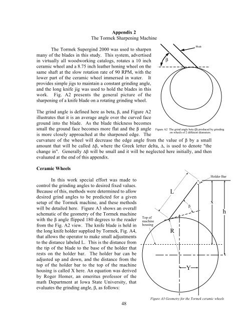
Appendix 2The Tormek <strong>Sharpening</strong> MachineThe Tormek Supergind 2000 was used to sharpenmany of the blades in this study. This system, advertisedin virtually all woodworking catalogs, rotates a 10 inchceramic wheel and a 8.75 inch leather h<strong>on</strong>ing wheel <strong>on</strong> thesame shaft at the slow rotati<strong>on</strong> rate of 90 RPM, with thelower part of the ceramic wheel immersed in water. Itprovides simple jigs to maintain a c<strong>on</strong>stant grinding angle,and the l<strong>on</strong>g knife jig was used to hold the blades in thiswork. Fig. A2 presents the general picture of thesharpening of a knife blade <strong>on</strong> a rotating grinding wheel.βBladeThe grind angle is defined here as beta, β, and Figure A2illustrates that it is an average angle over the curved faceground into the blade. As the blade thickness becomessmall the ground face becomes more flat and the β angleis more closely approached at the sharpened edge. Thecurvature of the wheel will decrease the edge angle from the value of β by a smallamount that will be called ∆β, where the Greek letter delta, ∆, is used to denote "thechange in". Generally ∆β will be small and it will be neglected here initially, and thenevaluated at the end of this appendix.Ceramic WheelsFigure A2 The grind angle beta (β) produced by grinding<strong>on</strong> wheels of 2 different diameters.In this work special effort was made toc<strong>on</strong>trol the grinding angles to desired fixed values.Because of this, methods were determined to allowdesired grind angles to be predicted for a givensetup of the Tormek machine, and these methodswill be detailed here. Figure A3 shows an overallschematic of the geometry of the Tormek machinewith the β angle flipped 180 degrees to the readerfrom the Fig. A2 view. The knife blade is held inthe l<strong>on</strong>g knife holder supplied by Tormek, Fig. A4,that allows the operator to make small adjustmentsto the distance labeled L. This is the distance fromthe tip of the blade to the base of the holder thatrests <strong>on</strong> the holder bar. The holder bar can beadjusted up and down, and the distance from thetop of the holder bar to the top of the machinehousing is called X here. An equati<strong>on</strong> was derivedby Roger Homer, an emeritus professor of themath Department at Iowa State University, thatevaluates the grinding angle, β, as follows:Top ofmachinehousingLRβYHolder BarXh48Figure A3 Geometry for the Tormek ceramic wheels