Experiments on Knife Sharpening John D. Verhoeven ... - BushcraftUK
Experiments on Knife Sharpening John D. Verhoeven ... - BushcraftUK
Experiments on Knife Sharpening John D. Verhoeven ... - BushcraftUK

Create successful ePaper yourself
Turn your PDF publications into a flip-book with our unique Google optimized e-Paper software.
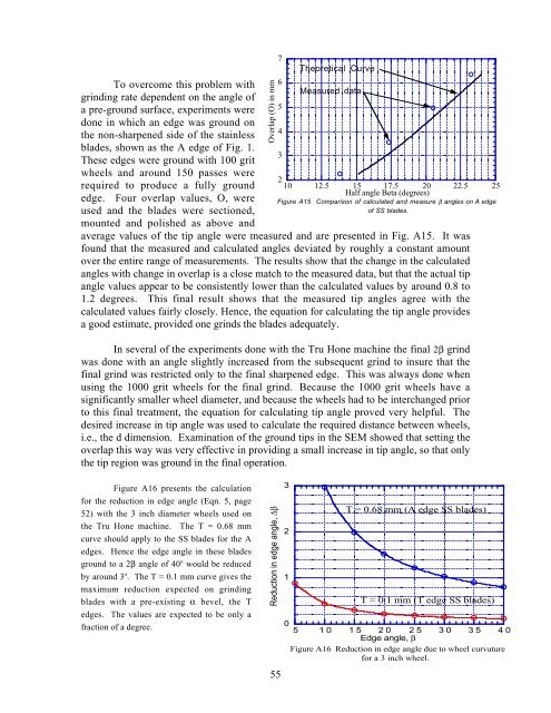
To overcome this problem withgrinding rate dependent <strong>on</strong> the angle ofa pre-ground surface, experiments wered<strong>on</strong>e in which an edge was ground <strong>on</strong>the n<strong>on</strong>-sharpened side of the stainlessblades, shown as the A edge of Fig. 1.These edges were ground with 100 gritwheels and around 150 passes wererequired to produce a fully groundedge. Four overlap values, O, wereused and the blades were secti<strong>on</strong>ed,mounted and polished as above andOverlap (O) in mm210 12.5 15 17.5 20 22.5 25Half angle Beta (degrees)Figure A15 Comparis<strong>on</strong> of calculated and measure β angles <strong>on</strong> A edgeof SS blades.average values of the tip angle were measured and are presented in Fig. A15. It wasfound that the measured and calculated angles deviated by roughly a c<strong>on</strong>stant amountover the entire range of measurements. The results show that the change in the calculatedangles with change in overlap is a close match to the measured data, but that the actual tipangle values appear to be c<strong>on</strong>sistently lower than the calculated values by around 0.8 to1.2 degrees. This final result shows that the measured tip angles agree with thecalculated values fairly closely. Hence, the equati<strong>on</strong> for calculating the tip angle providesa good estimate, provided <strong>on</strong>e grinds the blades adequately.In several of the experiments d<strong>on</strong>e with the Tru H<strong>on</strong>e machine the final 2β grindwas d<strong>on</strong>e with an angle slightly increased from the subsequent grind to insure that thefinal grind was restricted <strong>on</strong>ly to the final sharpened edge. This was always d<strong>on</strong>e whenusing the 1000 grit wheels for the final grind. Because the 1000 grit wheels have asignificantly smaller wheel diameter, and because the wheels had to be interchanged priorto this final treatment, the equati<strong>on</strong> for calculating tip angle proved very helpful. Thedesired increase in tip angle was used to calculate the required distance between wheels,i.e., the d dimensi<strong>on</strong>. Examinati<strong>on</strong> of the ground tips in the SEM showed that setting theoverlap this way was very effective in providing a small increase in tip angle, so that <strong>on</strong>lythe tip regi<strong>on</strong> was ground in the final operati<strong>on</strong>.76543Theoretical CurveMeasured dataFigure A16 presents the calculati<strong>on</strong>for the reducti<strong>on</strong> in edge angle (Eqn. 5, page52) with the 3 inch diameter wheels used <strong>on</strong>the Tru H<strong>on</strong>e machine. The T = 0.68 mmcurve should apply to the SS blades for the Aedges. Hence the edge angle in these bladesground to a 2β angle of 40 o would be reducedby around 3 o . The T = 0.1 mm curve gives themaximum reducti<strong>on</strong> expected <strong>on</strong> grindingblades with a pre-existing α bevel, the Tedges. The values are expected to be <strong>on</strong>ly afracti<strong>on</strong> of a degree.Reducti<strong>on</strong> in edge angle, ∆β55321T = 0.68 mm (A edge SS blades)T = 0.1 mm (T edge SS blades)05 10 15 20 25 30 35 40Edge angle, βFigure A16 Reducti<strong>on</strong> in edge angle due to wheel curvaturefor a 3 inch wheel.