Low-Voltage Delta-Sigma Audio ADC Using Switched RC ...
Low-Voltage Delta-Sigma Audio ADC Using Switched RC ...
Low-Voltage Delta-Sigma Audio ADC Using Switched RC ...

You also want an ePaper? Increase the reach of your titles
YUMPU automatically turns print PDFs into web optimized ePapers that Google loves.
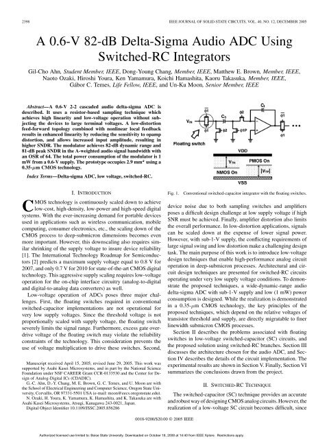
2398 IEEE JOURNAL OF SOLID-STATE CI<strong>RC</strong>UITS, VOL. 40, NO. 12, DECEMBER 2005A 0.6-V 82-dB <strong>Delta</strong>-<strong>Sigma</strong> <strong>Audio</strong> <strong>ADC</strong> <strong>Using</strong><strong>Switched</strong>-<strong>RC</strong> IntegratorsGil-Cho Ahn, Student Member, IEEE, Dong-Young Chang, Member, IEEE, Matthew E. Brown, Member, IEEE,Naoto Ozaki, Hiroshi Youra, Ken Yamamura, Koichi Hamashita, Kaoru Takasuka, Member, IEEE,Gábor C. Temes, Life Fellow, IEEE, and Un-Ku Moon, Senior Member, IEEEAbstract—A 0.6-V 2-2 cascaded audio delta-sigma <strong>ADC</strong> isdescribed. It uses a resistor-based sampling technique whichachieves high linearity and low-voltage operation without subjectingthe devices to large terminal voltages. A low-distortionfeed-forward topology combined with nonlinear local feedbackresults in enhanced linearity by reducing the sensitivity to opampdistortion, and allows increased input amplitude, resulting inhigher SNDR. The modulator achieves 82-dB dynamic range and81-dB peak SNDR in the A-weighted audio signal bandwidth withan OSR of 64. The total power consumption of the modulator is 1mW from a 0.6-V supply. The prototype occupies 2.9 mm 2 using a0.35- m CMOS technology.Index Terms—<strong>Delta</strong>-sigma <strong>ADC</strong>, low voltage, switched-<strong>RC</strong>.I. INTRODUCTIONCMOS technology is continuously scaled down to achievelow-cost, high-density, low-power and high-speed digitalsystems. With the ever-increasing demand for portable devicesused in applications such as wireless communication, mobilecomputing, consumer electronics, etc., the scaling down of theCMOS process to deep-submicron dimensions becomes evenmore important. However, this downscaling also requires similarshrinking of the supply voltage to insure device reliability[1]. The International Technology Roadmap for Semiconductors[2] predicts a maximum supply voltage equal to 0.8 V for2007, and only 0.7 V for 2010 for state-of-the-art CMOS digitaltechnology. This aggressive supply scaling requires low-voltageoperation for the on-chip interface circuitry (analog-to-digitaland digital-to-analog data converters) as well.<strong>Low</strong>-voltage operation of <strong>ADC</strong>s poses three major challenges.First, the floating switches required in conventionalswitched-capacitor implementations are not operational forvery low supply voltages. Since the threshold voltage is notproportionally scaled with supply voltage, the floating switchseverely limits the signal range. Furthermore, excess gate overdrivevoltage of the floating switch may violate the reliabilityconstraints of the technology. This consideration prevents theuse of voltage multiplication to drive these switches. Second,Manuscript received April 15, 2005; revised June 29, 2005. This work wassupported by Asahi Kasei Microsystems, and in part by the National ScienceFoundation under NSF CAREER Grant CCR-0133530 and the Center for Designof Analog-Digital ICs (CDADIC).G.-C. Ahn, D.-Y. Chang, M. E. Brown, G. C. Temes, and U. Moon are withthe School of Electrical Engineering and Computer Science, Oregon State University,Corvallis, OR 97331-5501 USA (e-mail: moon@eecs.oregonstate.edu).N. Ozaki, H. Youra, K. Yamamura, K. Hamashita, and K. Takasuka are withAsahi Kasei Microsystems, Atsugi, Kanagawa 243-0021, Japan.Digital Object Identifier 10.1109/JSSC.2005.856286Fig. 1.Conventional switched-capacitor integrator with the floating switches.device noise due to both sampling switches and amplifiersposes a difficult design challenge at low supply voltage if highSNR must be achieved. Finally, amplifier distortion also limitsthe overall performance. In low-distortion applications, signalscan be scaled down at the expense of lower signal power.However, with sub-1-V supply, the conflicting requirements oflarge signal swing and low distortion make a challenging designtask. The main purpose of this work is to introduce low-voltagedesign techniques that enable high-performance analog circuitoperation in deep-submicron processes. Architectural and circuitdesign techniques are presented for switched-<strong>RC</strong> circuitsoperating under very low supply voltage conditions. To demonstratethe proposed techniques, a wide-dynamic-range audiodelta-sigma <strong>ADC</strong> with sub-1-V supply and low (1 mW) powerconsumption is designed. While the realization is demonstratedin a 0.35- m CMOS technology, the key principles of theproposed techniques, which depend on the relative voltages oftransistor threshold and supply, are directly migratable to finerlinewidth submicron CMOS processes.Section II describes the problems associated with floatingswitches in low-voltage switched-capacitor (SC) circuits, andthe proposed solution using switched-<strong>RC</strong> branches. Section IIIdiscusses the architecture chosen for the audio <strong>ADC</strong>, and SectionIV describes the details of the circuit implementation. Theexperimental results are shown in Section V. Finally, Section VIsummarizes the conclusions drawn from the project.II. SWITCHED-<strong>RC</strong> TECHNIQUEThe switched-capacitor (SC) technique provides an accurateand robust way of designing CMOS analog circuits. However, therealization of a low-voltage SC circuit becomes difficult, since0018-9200/$20.00 © 2005 IEEEAuthorized licensed use limited to: Boise State University. Downloaded on October 18, 2008 at 14:40 from IEEE Xplore. Restrictions apply.
MOON et al.: A 0.6-V 82-dB DELTA-SIGMA AUDIO <strong>ADC</strong> USING SWITCHED-<strong>RC</strong> INTEGRATORS 2399Fig. 2.<strong>Low</strong>-voltage integrator with switched-<strong>RC</strong> input branch.the floating switches required in conventional SC circuits are notoperational for very low supply voltages. Fig. 1 shows a typicalSC integrator with its floating input and output switches. Limitedgate voltage under low supply restricts the operating range ofthese switches. For example, the NMOS switches are “on” onlywhen the input signal is lower than . Similarly, thePMOS switches are “on” only when the input signal is higherthan . Both transistors turn off in the mid-input signalrange. For proper operation, the gate overdrive voltage mustbe larger than the sum of the CMOS switch threshold voltagesand the input signal amplitude. Thus, higher gate overdrivevoltage has been used in previous low-voltage SC circuits, usingglobal clock boosting or bootstrapping by voltage multiplicationfor the clock signals [1], [3], [4]. However, both techniquesrequire extra circuitry and need careful design to avoid reliabilityproblems. There are several circuit techniques which are fullycompatible with low-voltage submicron CMOS processes, suchas switched-opamps (SO) [5]–[9] and the opamp-reset switchingtechnique(ORST)[10]–[12].However,SOcircuitsfaceatradeoffbetween speed and accuracy due to slow transients, while ORSTstages have higher power consumption and settling issues dueto unity gain feedback during the reset phase.In this work, a different solution based on the switched-<strong>RC</strong>technique is proposed, and is applied to the design of an audiodelta-sigma <strong>ADC</strong>. The basic concept is illustrated in Fig. 2. Asshown, the input SC branch of the conventional structure is replacedby a switched-<strong>RC</strong> branch, in which the floating switchof the conventional integrator is replaced by a resistor . Thismodification results in two advantages. First, it obviates the needfor the floating switch, and second, the linearity of the inputsampling is improved. The operation of this circuit is as follows.During the phase, the signal is sampled into the capacitorthrough resistor . During the following phase,the signal charge is transferred to the integrating capacitorby connecting the bottom plate of to ground through switch. During this phase, the voltage at node is determinedby the ratio of the ON resistance of the switch and theresistorThe output voltage of the integrator can be found from chargeconservation as(1)(2)The gain error due to the ON resistance of switch is thelast term in (2). For sufficiently high oversampling ratio (OSR),will be very close to , and the error canthen be approximated byNote that the gain error introduced by the nonideal ground atnode does not necessarily result in large distortion, as shownnext. In (3), is the only nonlinear term, and hence the solesource of nonlinearity. Its value is given in (4), which shows thatis a function of :Even though changes with the input signal, the signal variationat node is attenuated by the ratio of and [see(1)], and hence, the change in is small compared to thatof a floating switch. Both the nonlinearity of the input samplingand the gain error can be reduced by making the linearresistor much larger than the variable ON resistance of thereset switch . However, there is a tradeoff. Larger resultsin improved gain accuracy and lower distortion during thephase, but during the phase, a large time constantdegrades the sampling accuracy. Thus, should be smallenough to satisfy the settling requirement during the samplingphase.The gain of the opamp in a switched-<strong>RC</strong> (S<strong>RC</strong>) integratorchanges significantly between the phases. During the phase,the amplifier drives the resistive load , which results in a lowDC gain due to the low load impedance. However, during thisreset phase, the charge stored in will be preserved, and theoutput voltage of the integrator will be recovered in the followingphase, when the gain of amplifier returns to its highvalue as its resistive load is removed. The virtual ground voltagetherefore also returns to its low value needed for the chargetransfer. Hence, the effective DC gain of the amplifier in an S<strong>RC</strong>integrator can be the same as in a conventional SC one. Note alsothat the voltage between any two nodes is always less than thesupply voltage, and therefore this technique is free from devicereliability problems.As illustrated in Fig. 2, the phasing of the clock signals inadjacent S<strong>RC</strong> integrators must be shifted. Thus, there is adelay between the input and the output of the integrator, whereis the clock period.III. MODULATOR A<strong>RC</strong>HITECTUREAs discussed in Section I, there are three main problems inlow-voltage analog IC design. A circuit solution is proposed in(3)(4)Authorized licensed use limited to: Boise State University. Downloaded on October 18, 2008 at 14:40 from IEEE Xplore. Restrictions apply.
MOON et al.: A 0.6-V 82-dB DELTA-SIGMA AUDIO <strong>ADC</strong> USING SWITCHED-<strong>RC</strong> INTEGRATORS 2401Fig. 4.(a) Block diagram of two-stage cascaded delta-sigma modulator. (b) Digital noise cancellation logic.matching indicate higher than 100-dB SFDR of the completeconverter. More than 1.5-dB improvement in the permissiblepeak input signal due to local feedback is also observed in thesesimulations.IV. CI<strong>RC</strong>UIT IMPLEMENTATIONWhile the principle of the S<strong>RC</strong> circuit has been described inSection II, its actual implementation in our <strong>ADC</strong> is somewhatdifferent, since the input branches are also used for commonmodeadjustments and feedback. The implemented circuits willbe discussed next.A. Split <strong>Switched</strong>-<strong>RC</strong> Input BranchIn a low-voltage integrator, it is desirable to set the commonmode(CM) level of the input and output at the middle of thesupply voltage, i.e.,, to maximize signalswing. At the same time, any DC bias voltage connected tothe sampling capacitors must be close to or in orderto avoid any floating switching problem. For this reason, twodifferent input common-mode levels were applied to the integratorduring the sampling and the integrating phases. Such useof two different input CM voltages resulted in a large amountFig. 5. (a) Traditional low-voltage switched-capacitor integrator. (b) <strong>Low</strong>voltageintegrator with split switched-<strong>RC</strong> technique.of common-mode charge injection. Thus, the input or interstagebranches of all integrators should also perform a levelAuthorized licensed use limited to: Boise State University. Downloaded on October 18, 2008 at 14:40 from IEEE Xplore. Restrictions apply.
2402 IEEE JOURNAL OF SOLID-STATE CI<strong>RC</strong>UITS, VOL. 40, NO. 12, DECEMBER 2005Fig. 6.Schematic of pseudo-differential low-voltage integrator with switched-<strong>RC</strong> technique.shifting operation, in addition to sampling and transfer/amplificationof the input signal. Fig. 5(a) shows an earlier implementationof this level shifting in a low-voltage SC integrator [7]. Alevel-shifting capacitor is used to cancel the common-modecharge injection, by providing an opposite polarity charge. However,this added SC branch adds more noise and also increasesthe opamp noise gain.Inourimplementation,asplitinputswitched-<strong>RC</strong>branchisusedto keep constant CM level of the integrator, as shown in Fig. 5(b).During the integrating phase, one half of the sampling capacitoris connected to , while the other half is connected to . Thisresults in a constant input common-mode level of for theintegratorduringbothphases,obviatingtheneedforanadditionallevel-shifting capacitor without any noise penalty.B. Pseudo-Differential Integrator <strong>Using</strong> <strong>Switched</strong>-<strong>RC</strong>TechniqueFig. 6 shows the complete schematic of a pseudo-differentialintegrator using the switched-<strong>RC</strong> technique, and an exampletiming diagram. Split switched-<strong>RC</strong> input branches are used tomaintain a constant input common-mode voltage. The effectiveDAC reference voltage is doubled by alternating the connectionof the DAC capacitors from to or vice versa,depending on the comparator’s output. This helps to reducethe size of resulting in lower noise. This is because theinput-referred noise due to is scaled by ,and the opamp noise will be amplified by the ratio of andthe total capacitance connected to the virtual ground node.A pseudo-differential architecture is used to circumventchallenging design issues associated with low-voltagecommon-mode feedback circuit design. Capacitors s,connected to the switched-<strong>RC</strong> branches of the next stage, areused for the common-mode feedback. The basic operation ofthe switched-<strong>RC</strong> common-mode feedback is similar to thatproposed for pseudo-differential circuits earlier in [16], exceptfor the use of switched-<strong>RC</strong> branches. Fig. 7 shows the operationduring two different phases of common-mode feedback loopformed with the following stage switched-<strong>RC</strong> branches. During, the desired output common-mode reference is sampledonto capacitors by connecting half of them to and theother half to . During the following phase, the differencebetween and the actual output common-mode voltage is fedto all opamp inputs, and integrated in both pseudo-differentialpaths. This forces the output CM of all opamps to .Fig. 8 shows the complete schematic of the first-stage modulator,implemented in a pseudo-differential architecture. To insureless than 85-dB noise level, a total of 4.8-pF inputsampling capacitance is used and 8-k is used to guaranteelinear input signal sampling. The 1.5-bit DAC needed for localfeedback uses two capacitors to double the effectiveDAC reference voltage, each one acting as a 1-bit delay-freeDAC. During the phase, each capacitor is charged to or. During the following phase, depending on the output( 1, 0, or 1) of the 1.5-bit local feedback quantizer, the voltageat the bottom plate of the capacitors will be changed. Ifoutput is “ 1”, then the capacitor earlier connected to willAuthorized licensed use limited to: Boise State University. Downloaded on October 18, 2008 at 14:40 from IEEE Xplore. Restrictions apply.
MOON et al.: A 0.6-V 82-dB DELTA-SIGMA AUDIO <strong>ADC</strong> USING SWITCHED-<strong>RC</strong> INTEGRATORS 2403Fig. 7.Common-mode feedback with switched-<strong>RC</strong> technique. (a) 1 phase. (b) 2 phase.Fig. 8.First-stage delta-sigma modulator.be reconnected to .Ifitis“1”, then the capacitor connectedto will be switched to . However, if the quantizer outputis “0”, then the connection of the capacitors will not bechanged.The gain coefficients of the feed-forward paths from the<strong>ADC</strong> input and from the output nodes of each integrator to thequantizer input are realized simply by scaling the capacitorsin the comparators, as shown in Fig. 9. The switched-<strong>RC</strong>Authorized licensed use limited to: Boise State University. Downloaded on October 18, 2008 at 14:40 from IEEE Xplore. Restrictions apply.
2406 IEEE JOURNAL OF SOLID-STATE CI<strong>RC</strong>UITS, VOL. 40, NO. 12, DECEMBER 2005[13] R. Schreier and G. Temes, Understanding <strong>Delta</strong>-<strong>Sigma</strong> Data Converters.New York: Wiley/IEEE Press, 2004.[14] J. Silva, U. Moon, J. Steensgaard, and G. Temes, “Wideband low-distortiondelta-sigma <strong>ADC</strong> topology,” Electron. Lett., vol. 37, no. 12, pp.737–738, Jun. 2001.[15] I. Fujimori, K. Koyama, D. Trager, F. Tam, and L. Longo, “A 5 V singlechipdelta-sigma audio A/D converter with 111 dB dynamic range,”IEEE J. Solid-State Circuits, vol. 32, no. 3, pp. 329–336, Mar. 1997.[16] L. Wu, M. Keskin, U. Moon, and G. Temes, “Efficient common-modefeedback circuits for pseudo-differential switched-capacitor stages,”in Proc. IEEE Int. Symp. Circuits and Systems, vol. V, May 2000, pp.445–448.Fig. 14.SNDR and SFDR versus supply voltage.topology, while the peak SNDR is enhanced by increasingthe input signal range using quantized local feedback. Themeasured results of prototype IC fabricated in a 0.35- mCMOS technology verify the validity of the proposed designtechniques for low-voltage and high-performance operation.Gil-Cho Ahn (S’94) received the B.S. and M.S. degreesin electrical and electronics engineering fromSogang University, Seoul, Korea, and the Ph.D. degreein electrical engineering and computer scienceat Oregon State University, Corvallis, in 1994, 1996,and 2005, respectively.From 1996 to 2001, he was a Design Engineer withSamsung Electronics, Kiheung, Korea, working onmixed analog–digital integrated circuits. In 2005, hejoined Broadcom, Irvine, CA, as a Staff Scientist. Hiscurrent research interests include high-speed, highresolutiondata converters and low-voltage, low-power mixed-signal circuits design.Dr. Ahn received the Analog Devices Outstanding Student Designer Awardin 2003.ACKNOWLEDGMENTThe authors would like to thank P. K. Hanumolu, J. Silva, andM.-G. Kim of Oregon State University for useful discussions.REFERENCES[1] A. Abo and P. Gray, “A 1.5-V, 10-bit, 14.3-MS/s CMOS pipelineanalog-to-digital converter,” IEEE J. Solid-State Circuits, vol. 34, no.5, pp. 599–606, May 1999.[2] International Technology Roadmap for Semiconductors, SemiconductorIndustry Association (2004). [Online]. Available: http://public.itrs.net/[3] Y. Nakagome et al., “A 1.5 V circuit technology for 64 Mb DRAMs,” inDig. Symp. VLSI Circuits, Jun. 1990, pp. 17–18.[4] T. Cho and P. Gray, “A 10 b 20 Msamples/s, 35 mW pipeline A/D converter,”IEEE J. Solid-State Circuits, vol. 30, no. 3, pp. 166–172, Mar.1995.[5] J. Crols and M. Steyaert, “<strong>Switched</strong> opamp: An approach to realize fullCMOS SC circuits at very low supply voltages,” IEEE J. Solid-StateCircuits, vol. 29, no. 8, pp. 936–942, Aug. 1994.[6] V. Peluso, P. Vancorenland, A. Marques, M. Steyaert, and W. Sansen,“A 900-mV low-power 16 A/D converter with 77-dB dynamic range,”IEEE J. Solid-State Circuits, vol. 33, no. 12, pp. 1887–1897, Dec. 1998.[7] A. Baschirotto and R. Castello, “A 1-V 1.8-MHz CMOS switchedopampSC filter with rail-to-rail output swing,” IEEE J. Solid-StateCircuits, vol. 32, pp. 1979–1986, Dec. 1997.[8] M. Waltari and K. Halonen, “1-V 9-bit pipelined switched-opamp,”IEEE J. Solid-State Circuits, vol. 36, no. 1, pp. 129–134, Jan. 2001.[9] B. Vaz, J. Goes, and N. Paulino, “A 1.5-V 10-b 50 MS/s time-interleavedswitched-opamp pipeline CMOS <strong>ADC</strong> with high energy efficiency,” inDig. Symp. VLSI Circuits, Jun. 2004, pp. 432–435.[10] M. Keskin, U. Moon, and G. Temes, “A 1-V 10-MHz clock-rate 13-bitCMOS 16 modulator using unity-gain-reset opamps,” IEEE J. Solid-State Circuits, vol. 37, no. 7, pp. 817–823, Jul. 2002.[11] D. Chang, G. Ahn, and U. Moon, “A 0.9 V 9 mW 1 MSPS digitallycalibrated <strong>ADC</strong> with 75 dB SFDR,” in Dig. Symp. VLSI Circuits, Jun.2003, pp. 67–70.[12] D. Chang and U. Moon, “A 1.4-V 10-bit 25 MSPS pipelined <strong>ADC</strong> usingopamp-reset switching technique,” IEEE J. Solid-State Circuits, vol. 38,no. 8, pp. 1401–1404, Aug. 2003.Dong-Young Chang (S’00–M’04) received the B.Sand M.S. degrees in electronic engineering from SogangUniversity, Seoul, Korea, and the Ph.D. degreein electrical and computer engineering from OregonState University, Corvallis, in 1995, 1997, and 2002,respectively.He joined Samsung Electronics, Kiheung, Korea,in 1997, where he was engaged in the design ofanalog front-end systems for CCD/CMOS imagesensors and LCD displays. During the summerof 2000, he was with Lucent Technologies, BellLaboratories, Allentown, PA, where he investigated various low-voltage dataconverters. From January 2003 to March 2005, he was with Texas InstrumentsIncorporated, Tucson, AZ, working on low-power high-speed <strong>ADC</strong> products.In 2005, he joined Engim Inc., Acton, MA, as a Senior Analog Engineer.His research has been focused on low-voltage and low-power analog andmixed-mode integrated circuits. He holds three U.S. patents.Dr. Chang received the Outstading Student Paper Award from the IEEE Solid-State Circuits Seoul Chapter in 1998 and the Analog Devices Outstanding StudentDesigner Award in 2000.Matthew E. Brown (M’99) was born in SantaBarbara, California. He received the B.Sc. degree inelectrical and electronics engineering from OregonState University, Corvallis, in 2001. He is presentlyworking toward the M.S. degree in electrical engineeringand computer science at Oregon StateUniversity.From 2001 to 2004, he was a Graduate ResearchAssistant in the Analog Group at Oregon State University,where he worked on the design of low-voltagecircuits including switched-capacitor data convertersand low-noise programmable-gain audio amplifiers. Since 2004, he has workedas an R&D Engineer for the Process and Device Integration Group, Hewlett-Packard Company, Corvallis, OR.Authorized licensed use limited to: Boise State University. Downloaded on October 18, 2008 at 14:40 from IEEE Xplore. Restrictions apply.
MOON et al.: A 0.6-V 82-dB DELTA-SIGMA AUDIO <strong>ADC</strong> USING SWITCHED-<strong>RC</strong> INTEGRATORS 2407Naoto Ozaki was born in Niigata, Japan, in 1968.He received the B.S. and M.S. degrees in electronicsengineering from Nagaoka University of Technology,Japan, in 1992 and 1994, respectively.In 1994, he joined the LSI Design and DevelopmentCenter of Asahi Kasei Microsystems,Kanagawa, Japan. Since then, he has been engagedin the development of CMOS mixed-signal LSIsfor digital audio. His current interest is in the developmentof low-power delta-sigma A/D and D/Aconverters for digital audio.Hiroshi Youra was born in Yamaguchi, Japan, in1971. He received the B.S. degree in engineeringscience from University of Osaka, Osaka, Japan,in 1994 and the M.S. degree in information sciencefrom Nara Institute of Science and Technology,Nara, Japan, in 1996.He subsequently joined the Design and DevelopmentCenter of Asahi Kasei Microsystems,Kanagawa, Japan. Since then, he has been engagedin the research and development of mixed-signalCMOS LSIs for digital audio. His current interestis in the development of low-power and high-resolution delta-sigma A/D andD/A converters for digital audio.Ken Yamamura was born in Osaka, Japan, onMarch 31, 1958. He received the M.S. degree ininstrumentation engineering from Keio University,Japan, in 1982.In 1982, he joined Asahi Kasei Chemical, developedmedical analyzing systems. Since 1983, he hasbeen with Asahi Kasei Microsystems, Kanagawa,Japan, developing audio data converter LSIs. Hiscurrent research interests include high-resolution,low-power data converters and audio circuit designand integration.Gábor C. Temes (SM’66–F’73–LF’98) received theundergraduate degrees from the Technical Universityof Budapest and Eötvös University, Budapest, Hungary,in 1952 and 1955, respectively. He received thePh.D. degree in electrical engineering from the Universityof Ottawa, Ottawa, ON, Canada, in 1961, andan honorary doctorate from the Technical Universityof Budapest in 1991.He held academic positions at the Technical Universityof Budapest, Stanford University, Stanford,CA, and the University of California at Los Angeles(UCLA). He worked in industry at Northern Electric R&D Laboratories (nowBell-Northern Research), Ottawa, Canada, as well as at Ampex Corporation.He is now a Professor in the School of Electrical Engineering and ComputerScience at Oregon State University (OSU), Corvallis. He has served as DepartmentHead at both UCLA and OSU. He has co-edited and co-authored manybooks; the most recent one is Understanding <strong>Delta</strong>-<strong>Sigma</strong> Data Converters (R.Schreier and G. C. Temes, IEEE Press/ Wiley, 2005). He has also written approximately300 papers in engineering journals and conference proceedings.His recent research has dealt with CMOS analog integrated circuits, as well asdata converters.Dr. Temes has been an Associate Editor of the Journal of the Franklin Institute,Editor of the IEEE TRANSACTIONS ON CI<strong>RC</strong>UIT THEORY, and Vice Presidentof the IEEE Circuits and Systems (CAS) Society. In 1968 and 1981, hewas co-winner of the IEEE CAS Darlington Award, and in 1984 winner of theCentennial Medal of the IEEE. He received the Andrew Chi Prize Award of theIEEE Instrumentation and Measurement Society in 1985, the Education Awardof the IEEE CAS Society in 1987, and the Technical Achievement Award of theIEEE CAS Society in 1989. He received the IEEE Graduate Teaching Award in1998, and the IEEE Millennium Medal as well as the IEEE CAS Golden JubileeMedal in 2000.Koichi Hamashita (M’89) was born in Ishikawa,Japan, in 1957. He received the B.S. and M.S.degrees in mechanical engineering from Kyoto University,Kyoto, Japan, in 1979 and 1981, respectively.He joined Asahi Kasei in 1981. Since 1985, he hasbeen engaged in the design of CMOS LSIs, especiallyin the field of delta-sigma <strong>ADC</strong>s and DACs. He is currentlyDirector-Chief Design and Development Officerof Asahi Kasei Microsystems, Atsugi, Japan.Kaoru Takasuka (M’99) was born in Hiroshima,Japan, in 1947. He received the B.S. and M.S.degrees in instrumentation engineering from theKyushu Institute of Technology, Kitakyushu, Japan,in 1970 and 1972, respectively.He joined Asahi Kasei in 1972. Since 1983, he hasbeen engaged in the design of custom CMOS LSIs.He is currently the Vice President-CTO of AsahiKasei Microsystems, Tokyo, Japan.Mr. Takasuka was a corecipient of the Award forTechnical Excellence from the Society of Instrumentand Control Engineers of Japan in 1986 and the Institute of Electrical Engineersof Japan Millennium Best Paper Award in 2001.Un-Ku Moon (S’92–M’94–SM’99) received theB.S. degree from the University of Washington,Seattle, in 1987, the M.Eng. degree from CornellUniversity, Ithaca, NY, in 1989, and the Ph.D. degreefrom the University of Illinois at Urbana-Champaignin 1994, all in electrical engineering.He has been with the School of Electrical Engineeringand Computer Science, Oregon State University,Corvallis, since 1998, where he is currentlya Professor. Before joining Oregon State University,he was with Bell Laboratories from 1988 to 1989,and from 1994 to 1998. His technical contributions have been in the area ofanalog and mixed-signal circuits including highly linear and tunable continuous-timefilters, telecommunication circuits including timing recovery and dataconverters, and ultra-low-voltage analog circuits for CMOS.Prof. Moon is a recipient of the National Science Foundation CAREERAward, and the Engelbrecht Young Faculty Award from Oregon State UniversityCollege of Engineering. He has served as an Associate Editor of the IEEETRANSACTIONS ON CI<strong>RC</strong>UITS AND SYSTEMS II: ANALOG AND DIGITAL SIGNALPROCESSING. He currently serves as an Associate Editor of the IEEE JOURNALOF SOLID-STATE CI<strong>RC</strong>UITS. He also serves on the Technical Program Committeeof the IEEE Custom Integrated Circuits Conference and the Analog SignalProcessing Technical Comittee of the IEEE Circuits and Systems Society.Authorized licensed use limited to: Boise State University. Downloaded on October 18, 2008 at 14:40 from IEEE Xplore. Restrictions apply.