Loop Stability Analysis.pdf
Loop Stability Analysis.pdf
Loop Stability Analysis.pdf
- No tags were found...

Create successful ePaper yourself
Turn your PDF publications into a flip-book with our unique Google optimized e-Paper software.
Department of Electrical and Computer Engineering<strong>Loop</strong> <strong>Stability</strong> <strong>Analysis</strong>Differential Opamp SimulationVishal Saxena & Zhu KehanBoise State University(vishalsaxena@boisestate.edu)© Vishal Saxena -1-
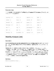
Spectre STB <strong>Analysis</strong>The STB analysis linearizes the circuit about the DC operating pointand computes the loop-gain, gain and phase margins (if the sweepvariable is frequency), for a feedback loop or a gain device [1].Refer to the Spectre Simulation Refrence [1] and [2] for details.Uses return ratio analysis method to calculate loop-gain and phasemargin ([3, 4]).© Vishal Saxena -2-
Example Single-ended Opamp Schematic© Vishal Saxena -3-
Simulation SetupAlways have dc analysis on for debugging purpose© Vishal Saxena -6-
Bode Plot SetupResults →Direct Plot →Main Form© Vishal Saxena -7-
<strong>Loop</strong> Response Bode Plots Here, f un =152.5 MHz, PM=41.8º Try to use the stb analysis while the circuit is in the desired feedbackconfiguration• Break the loop with realistic DC operating points© Vishal Saxena -8-
Transient Step Response Test BenchTransient step-response verifies the closed-loop stabilityUse small as wells as large steps for characterizationiprobe acts as a short (can remove it from transient sims)© Vishal Saxena -9-
Small Step Response Observe the ringing (PM was 41º)• Compensate more!• Correlate small-step response with the open-loop frequency responsefor your understanding.© Vishal Saxena -10-
Large Step ResponseUse large steps for large signal response• Not captured by the small-signal analysis• Note the slewing in the output here© Vishal Saxena -11-
Fully-Differential OpampSimulationContinuous-time CMFB© Vishal Saxena -12-
CMDM Probe Located in library: AnalogLib→cmdmprobe Variable CMDM =• -1 measures differential mode response• +1 measures common mode response In IC615, diffstbprobe is available which handles unbalanceddifferential circuits better than the cmdmprobe. More information on the differential probes and the STB analysisalgorithm can be found in [4].© Vishal Saxena -13-
Fully Differential Circuit <strong>Analysis</strong> Use CMDM probe for differential analysis [1, 3] Placement of the CMDM probe should break the differential as wellthe common-mode loops.© Vishal Saxena -14-
Fully Differential Circuit <strong>Analysis</strong> Method1For internal loops, isolate those loops individually and perform STBanalysis• Ensure overall DC feedback for accurate biasing and that all loops arecompensated• CMDM 1measures only the first-stage CM response• CMDM 2measures overall DM response and second-stage CM response© Vishal Saxena -15-
Fully Differential Circuit <strong>Analysis</strong> Method2cmdmprobes placed outside DM loop, only in CMFB loops• CMDM 1measures only the first-stage CM response• CMDM 2measures only the second-stage CM response• But need another CMDM probe to measure DM loop stability• Results match with iprobe results very well.© Vishal Saxena -16-
Fully Differential Opamp SchematicTwo-stage fully differential opampClass AB output stage for large voltage swingWith individual CMFB.1st stage CMFB compensated© Vishal Saxena © Vishal and Venkatesh Saxena Acharya -17-
STB <strong>Analysis</strong> Using Method 1Be noted that the nulling resistors should be connected before theinputs of cmdmprobe in the 1 st CMFB loop, or it will generateincorrect results.© Vishal Saxena © Vishal and Venkatesh Saxena Acharya -18-
STB <strong>Analysis</strong> Using Method 2Need one extra cmdmprobe to measure DM loop comparing tomethod 1.© Vishal Saxena © Vishal and Venkatesh Saxena Acharya -19-
DM <strong>Loop</strong> Bode Plots M1&M2 Differential Mode loop gain and phase margin plots Same results obtained by using Method 1 and Method 2© Vishal Saxena -20-
1 st Stage CMFB <strong>Loop</strong> Bode PlotsMethod 1Method 2© Vishal Saxena -21-
2 nd Stage CMFB <strong>Loop</strong> Bode PlotsMethod 1 Method 2© Vishal Saxena -22-
Simulation SetupUse previous oppt (operating point) in the stb analysis© Vishal Saxena -23-
Bode Plot SetupResults → Direct Plot → Main Form© Vishal Saxena -24-
DM TransientUnity- gain inverting amplifier transient response with a 200mVdifferential step (rise/fall time=0.1ns, pulse with=100ns)© Vishal Saxena -25-
CM TransientUnity- gain inverting amplifier transient response with a 100mVcommon mode step (rise/fall time=0.1ns, pulse with=100ns)© Vishal Saxena -26-
Fully-Differential OpampSimulationSwitched-capacitor CMFB© Vishal Saxena -27-
Switched Capacitor CMFB Simulation2-stage Class AB output OpampIndividual SC-CMFB© Vishal Saxena -28-
PSTB <strong>Analysis</strong> Using Method 1PSTB analysis is essential for sampled circuit© Vishal Saxena © Vishal and Venkatesh Saxena Acharya -29-
Simulation Setup---PSSWe can only set the number of harmonics to 0 by choosing Shootingmethodtstab parameter can be obtained by tran analysis first© Vishal Saxena -30-
PSS Accuracy suggestionsGo to Simulation Options Analog Main in the ADE window tosetup tolerance options accordingly. If the frequency of periodic smallsignal analyses followed by PSS is high (e.g. 1G), the maxacfreqparameter (optionsaccuracy) of the PSS can be used to specify thehighest frequency, otherwise, the frequency analysis in PAC maybetruncated.© Vishal Saxena -31-
PSS Time PlotResults → Direct Plot → Main FormX-axis scale range is 1/sampling clock frequency© Vishal Saxena -32-
PSTB SetupPSTB is always followed by PSS© Vishal Saxena -33-
PSTB PlotResults → Direct Plot → Main Form© Vishal Saxena -34-
DM <strong>Loop</strong> Bode PlotsResistive feedbackCapacitive feedback© Vishal Saxena -35-
1 st Stage CMFB <strong>Loop</strong> Bode PlotsResistive feedbackCapacitive feedback© Vishal Saxena -36-
2 nd Stage CMFB <strong>Loop</strong> Bode PlotsResistive feedbackCapacitive feedback© Vishal Saxena -37-
Summary of pstb analysis© Vishal Saxena © Vishal and Venkatesh Saxena Acharya -38-
Resistive Feedback DM TransientUnity- gain inverting amplifier transient response with a 200mVdifferential step (rise/fall time=0.1ns, pulse with=200ns)© Vishal Saxena -39-
Resistive Feedback CM TransientUnity- gain inverting amplifier transient response with a 100mVcommon mode step (rise/fall time=0.1ns, pulse with=200ns)© Vishal Saxena -40-
Sample-Hold ConfigurationIdeal switches with on resistance of 1kΩ© Vishal Saxena -41-
Sample-Hold Transient ResponseDM and CM outputs waveforms when fin=1/4 MHz, fs=5MHz© Vishal Saxena -42-
Sample-Hold Transient ResponseDM and CM outputs waveforms when fin=11/4 MHz, fs=5MHz© Vishal Saxena -43-
References[1] Spectre User Simulation Guide, pages 160-165[2] M. Tian, V. Viswanathan, J. Hangtan, K. Kundert, “Striving for Small-Signal<strong>Stability</strong>: <strong>Loop</strong>-based and Device-based Algorithms for <strong>Stability</strong> <strong>Analysis</strong> of LinearAnalog Circuits in the Frequency Domain,” Circuits and Devices, Jan 2001.[3] P. R. Gray, P. J. Hurst, S. H. Lewis, R. G. Meyer, “Analog and Design of AnalogIntegrated Circuits,” 4th Ed., Wiley, 2010.[4] F. Wiedmann, “<strong>Loop</strong> gain simulation,” Online:https://sites.google.com/site/frankwiedmann/loopgain© Vishal Saxena -44-