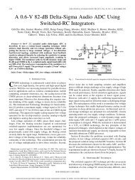
Matlab Filter Design and Implementation.pdf
Matlab Filter Design and Implementation.pdf
Matlab Filter Design and Implementation.pdf

Create successful ePaper yourself
Turn your PDF publications into a flip-book with our unique Google optimized e-Paper software.
IIR <strong>Filter</strong> <strong>Design</strong><strong>Filter</strong> Method Description <strong>Filter</strong> FunctionsAnalogPrototypingDirect <strong>Design</strong>GeneralizedButterworth<strong>Design</strong>ParametricModelingUsing the poles <strong>and</strong> zeros ofa classical lowpassprototype filter in thecontinuous (Laplace)domain, obtain a digitalfilter through frequencytransformation <strong>and</strong> filterdiscretization.<strong>Design</strong> digital filter directlyin the discrete time-domainby approximating apiecewise linear magnituderesponse.<strong>Design</strong> lowpassButterworth filters withmore zeros than poles.Find a digital filter thatapproximates a prescribedtime or frequency domainresponse. (See the SystemIdentification Toolboxdocumentation for anextensive collection ofparametric modeling tools.)Complete design functions:besself, butter, cheby1, cheby2, ellipOrder estimation functions:buttord, cheb1ord, cheb2ord, ellipordLowpass analog prototype functions:besselap, buttap, cheb1ap, cheb2ap, ellipapFrequency transformation functions:lp2bp, lp2bs, lp2hp, lp2lp<strong>Filter</strong> discretization functions:bilinear, impinvaryulewalkmaxflatTime-domain modeling functions:lpc, prony, stmcbFrequency-domain modeling functions:invfreqs, invfreqz2-5
IIR <strong>Filter</strong> <strong>Design</strong>Chebyshev Type II <strong>Filter</strong>The Chebyshev Type II filter minimizes the absolute difference between theideal <strong>and</strong> actual frequency response over the entire stopb<strong>and</strong> by incorporatingan equal ripple of Rs dB in the stopb<strong>and</strong>. Passb<strong>and</strong> response is maximally flat.The stopb<strong>and</strong> does not approach zero as quickly as the type I filter (<strong>and</strong> doesnot approach zero at all for even-valued filter order n). The absence of ripple inRs 20the passb<strong>and</strong>, however, is often an important advantage. H( jΩ) = 10 – ⁄at Ω = 1 .10.8Magnitude0.60.40.2010 -1 10 0 10 1Frequency(rad/sec)2-11
2 <strong>Filter</strong> <strong>Design</strong> <strong>and</strong> <strong>Implementation</strong>Elliptic <strong>Filter</strong>Elliptic filters are equiripple in both the passb<strong>and</strong> <strong>and</strong> stopb<strong>and</strong>. Theygenerally meet filter requirements with the lowest order of any supported filtertype. Given a filter order n, passb<strong>and</strong> ripple Rp in decibels, <strong>and</strong> stopb<strong>and</strong> rippleRp 20Rs in decibels, elliptic filters minimize transition width. H( jΩ) = 10 – ⁄ atΩ = 1 .10.8Magnitude0.60.40.2010 -1 10 0 10 1Frequency(rad/sec)2-12
IIR <strong>Filter</strong> <strong>Design</strong>Bessel <strong>Filter</strong>Analog Bessel lowpass filters have maximally flat group delay at zerofrequency <strong>and</strong> retain nearly constant group delay across the entire passb<strong>and</strong>.<strong>Filter</strong>ed signals therefore maintain their waveshapes in the passb<strong>and</strong>frequency range. Frequency mapped <strong>and</strong> digital Bessel filters, however, do nothave this maximally flat property; this toolbox supports only the analog casefor the complete Bessel filter design function.Bessel filters generally require a higher filter order than other filters forsatisfactory stopb<strong>and</strong> attenuation. H( jΩ) < 1⁄2 at Ω = 1 <strong>and</strong> decreases asfilter order n increases.10.8Magnitude0.60.40.2010 -1 10 0 10 1Frequency(rad/sec)Note The lowpass filters shown above were created with the analogprototype functions besselap, buttap, cheb1ap, cheb2ap, <strong>and</strong> ellipap. Thesefunctions find the zeros, poles, <strong>and</strong> gain of an order n analog filter of theappropriate type with cutoff frequency of 1 rad/s. The complete filter designfunctions (besself, butter, cheby1, cheby2, <strong>and</strong> ellip) call the prototypingfunctions as a first step in the design process. See ““Special Topics in IIR<strong>Filter</strong> <strong>Design</strong>” on page 2-44” for details.2-13
IIR <strong>Filter</strong> <strong>Design</strong><strong>Design</strong> a multib<strong>and</strong> filter with yulewalk, <strong>and</strong> plot the desired <strong>and</strong> actualfrequency response:m = [0 0 1 1 0 0 1 1 0 0];f = [0 0.1 0.2 0.3 0.4 0.5 0.6 0.7 0.8 1];[b,a] = yulewalk(10,f,m);[h,w] = freqz(b,a,128)plot(f,m,w/pi,abs(h))1.210.80.60.40.200 0.1 0.2 0.3 0.4 0.5 0.6 0.7 0.8 0.9 1Generalized Butterworth <strong>Filter</strong> <strong>Design</strong>The toolbox function maxflat enables you to design generalized Butterworthfilters, that is, Butterworth filters with differing numbers of zeros <strong>and</strong> poles.This is desirable in some implementations where poles are more expensivecomputationally than zeros. maxflat is just like the butter function, exceptthat it you can specify two orders (one for the numerator <strong>and</strong> one for thedenominator) instead of just one. These filters are maximally flat. This meansthat the resulting filter is optimal for any numerator <strong>and</strong> denominator orders,with the maximum number of derivatives at 0 <strong>and</strong> the Nyquist frequency ω = πboth set to 0.2-15
2 <strong>Filter</strong> <strong>Design</strong> <strong>and</strong> <strong>Implementation</strong>For example, when the two orders are the same, maxflat is the same as butter:[b,a] = maxflat(3,3,0.25)b =a =0.0317 0.0951 0.0951 0.03171.0000 -1.4590 0.9104 -0.1978[b,a] = butter(3,0.25)b =a =0.0317 0.0951 0.0951 0.03171.0000 -1.4590 0.9104 -0.1978However, maxflat is more versatile because it allows you to design a filter withmore zeros than poles:[b,a] = maxflat(3,1,0.25)b =a =0.0950 0.2849 0.2849 0.09501.0000 -0.2402The third input to maxflat is the half-power frequency, a frequency between0 <strong>and</strong> 1 with a desired magnitude response of 1⁄2 .You can also design linear phase filters that have the maximally flat propertyusing the 'sym' option:maxflat(4,'sym',0.3)ans =0.0331 0.2500 0.4337 0.2500 0.0331For complete details of the maxflat algorithm, see Selesnick <strong>and</strong> Burrus [2].2-16
FIR <strong>Filter</strong> <strong>Design</strong>FIR <strong>Filter</strong> <strong>Design</strong>Digital filters with finite-duration impulse response (all-zero, or FIR filters)have both advantages <strong>and</strong> disadvantages compared to infinite-durationimpulse response (IIR) filters.FIR filters have the following primary advantages:• They can have exactly linear phase.• They are always stable.• The design methods are generally linear.• They can be realized efficiently in hardware.• The filter startup transients have finite duration.The primary disadvantage of FIR filters is that they often require a muchhigher filter order than IIR filters to achieve a given level of performance.Correspondingly, the delay of these filters is often much greater than for anequal performance IIR filter.<strong>Filter</strong> Method Description <strong>Filter</strong> FunctionsWindowingMultib<strong>and</strong> withTransitionB<strong>and</strong>sConstrainedLeast SquaresArbitraryResponseRaised CosineApply window to truncatedinverse Fourier transform ofdesired “brick wall” filterEquiripple or least squaresapproach over sub-b<strong>and</strong>s of thefrequency rangeMinimize squared integralerror over entire frequencyrange subject to maximumerror constraintsArbitrary responses, includingnonlinear phase <strong>and</strong> complexfiltersLowpass response withsmooth, sinusoidal transitionfir1, fir2,kaiserordfirls, firpm,firpmordfircls, fircls1cfirpmfirrcos2-17
2 <strong>Filter</strong> <strong>Design</strong> <strong>and</strong> <strong>Implementation</strong>Linear Phase <strong>Filter</strong>sExcept for cfirpm, all of the FIR filter design functions design linear phasefilters only. The filter coefficients, or “taps,” of such filters obey either an evenor odd symmetry relation. Depending on this symmetry, <strong>and</strong> on whether theorder n of the filter is even or odd, a linear phase filter (stored in length n+1vector b) has certain inherent restrictions on its frequency response.Linear Phase<strong>Filter</strong> Type<strong>Filter</strong>OrderSymmetry of CoefficientsResponse H(f),f = 0Response H(f),f = 1 (Nyquist)Type I Even even: No restriction No restrictionType II Oddb( k) = b( n + 2 – k) , k = 1, …,n + 1No restriction H(1) = 0Type III Even odd: H(0) = 0 H(1) = 0Type IV Oddb( k) = – b( n + 2 – k) , k = 1, …,n + 1H(0) = 0 No restrictionThe phase delay <strong>and</strong> group delay of linear phase FIR filters are equal <strong>and</strong>constant over the frequency b<strong>and</strong>. For an order n linear phase FIR filter, thegroup delay is n/2, <strong>and</strong> the filtered signal is simply delayed by n/2 time steps(<strong>and</strong> the magnitude of its Fourier transform is scaled by the filter’s magnituderesponse). This property preserves the wave shape of signals in the passb<strong>and</strong>;that is, there is no phase distortion.The functions fir1, fir2, firls, firpm, fircls, fircls1, <strong>and</strong> firrcos alldesign type I <strong>and</strong> II linear phase FIR filters by default. Both firls <strong>and</strong> firpmdesign type III <strong>and</strong> IV linear phase FIR filters given a 'hilbert' or'differentiator' flag. cfirpm can design any type of linear phase filter, <strong>and</strong>nonlinear phase filters as well.Note Because the frequency response of a type II filter is zero at the Nyquistfrequency (“high” frequency), fir1 does not design type II highpass <strong>and</strong>b<strong>and</strong>stop filters. For odd-valued n in these cases, fir1 adds 1 to the order <strong>and</strong>returns a type I filter.2-18
FIR <strong>Filter</strong> <strong>Design</strong>Windowing MethodConsider the ideal, or “brick wall,” digital lowpass filter with a cutoff frequencyof ω 0 rad/s. This filter has magnitude 1 at all frequencies with magnitude lessthan ω 0 , <strong>and</strong> magnitude 0 at frequencies with magnitude between ω 0 <strong>and</strong> π. Itsimpulse response sequence h(n) ish( n)π1------ H( ω)e 2πjωn 1=dω= ------ e–π2πjωn dω=–ω 0ω 0ω 0------sinc ω 0(------n)π πThis filter is not implementable since its impulse response is infinite <strong>and</strong>noncausal. To create a finite-duration impulse response, truncate it byapplying a window. By retaining the central section of impulse response in thistruncation, you obtain a linear phase FIR filter. For example, a length 51 filterwith a lowpass cutoff frequency ω 0 of 0.4π rad/s isb = 0.4*sinc(0.4*(-25:25));The window applied here is a simple rectangular window. By Parseval’stheorem, this is the length 51 filter that best approximates the ideal lowpassfilter, in the integrated least squares sense. The following comm<strong>and</strong> displaysthe filter’s frequency response in FVTool:fvtool(b,1)Note that the y-axis shown in the figure below is in Magnitude Squared. Youcan set this by right-clicking on the axis label <strong>and</strong> selecting MagnitudeSquared from the menu.2-19
2 <strong>Filter</strong> <strong>Design</strong> <strong>and</strong> <strong>Implementation</strong>Ringing <strong>and</strong> ripples occur in the response, especially near the b<strong>and</strong> edge. This“Gibbs effect” does not vanish as the filter length increases, but anonrectangular window reduces its magnitude. Multiplication by a window inthe time domain causes a convolution or smoothing in the frequency domain.Apply a length 51 Hamming window to the filter <strong>and</strong> display the result usingFVTool:b = 0.4*sinc(0.4*(-25:25));b = b.*hamming(51)';fvtool(b,1)2-20
2 <strong>Filter</strong> <strong>Design</strong> <strong>and</strong> <strong>Implementation</strong>window by default, but they accept any window function. See the “Windows” onpage 4-2 for an overview of windows <strong>and</strong> their properties.St<strong>and</strong>ard B<strong>and</strong> FIR <strong>Filter</strong> <strong>Design</strong>: fir1fir1 implements the classical method of windowed linear phase FIR digitalfilter design. It resembles the IIR filter design functions in that it is formulatedto design filters in st<strong>and</strong>ard b<strong>and</strong> configurations: lowpass, b<strong>and</strong>pass, highpass,<strong>and</strong> b<strong>and</strong>stop.The statementsn = 50;Wn = 0.4;b = fir1(n,Wn);create row vectorb containing the coefficients of the order nHamming-windowed filter. This is a lowpass, linear phase FIR filter with cutofffrequency Wn. Wn is a number between 0 <strong>and</strong> 1, where 1 corresponds to theNyquist frequency, half the sampling frequency. (Unlike other methods, hereWn corresponds to the 6 dB point.) For a highpass filter, simply append thestring 'high' to the function’s parameter list. For a b<strong>and</strong>pass or b<strong>and</strong>stopfilter, specify Wn as a two-element vector containing the passb<strong>and</strong> edgefrequencies; append the string 'stop' for the b<strong>and</strong>stop configuration.b = fir1(n,Wn,window) uses the window specified in column vector window forthe design. The vector window must be n+1 elements long. If you do not specifya window, fir1 applies a Hamming window.Kaiser Window Order Estimation. The kaiserord function estimates the filterorder, cutoff frequency, <strong>and</strong> Kaiser window beta parameter needed to meet agiven set of specifications. Given a vector of frequency b<strong>and</strong> edges <strong>and</strong> acorresponding vector of magnitudes, as well as maximum allowable ripple,kaiserord returns appropriate input parameters for the fir1 function.Multib<strong>and</strong> FIR <strong>Filter</strong> <strong>Design</strong>: fir2The fir2 function also designs windowed FIR filters, but with an arbitrarilyshaped piecewise linear frequency response. This is in contrast to fir1, whichonly designs filters in st<strong>and</strong>ard lowpass, highpass, b<strong>and</strong>pass, <strong>and</strong> b<strong>and</strong>stopconfigurations.2-22
FIR <strong>Filter</strong> <strong>Design</strong>The comm<strong>and</strong>sn = 50;f = [0 .4 .5 1];m = [1 1 0 0];b = fir2(n,f,m);return row vector b containing the n+1 coefficients of the order n FIR filterwhose frequency-magnitude characteristics match those given by vectors f<strong>and</strong> m.f is a vector of frequency points ranging from 0 to 1, where 1 representsthe Nyquist frequency. m is a vector containing the desired magnitude responseat the points specified inf. (The IIR counterpart of this function is yulewalk,which also designs filters based on arbitrary piecewise linear magnituderesponses. See “IIR <strong>Filter</strong> <strong>Design</strong>” on page 2-4 for details.)Multib<strong>and</strong> FIR <strong>Filter</strong> <strong>Design</strong> with Transition B<strong>and</strong>sThe firls <strong>and</strong> firpm functions provide a more general means of specifying theideal desired filter than the fir1 <strong>and</strong> fir2 functions. These functions designHilbert transformers, differentiators, <strong>and</strong> other filters with odd symmetriccoefficients (type III <strong>and</strong> type IV linear phase). They also let you includetransition or “don’t care” regions in which the error is not minimized, <strong>and</strong>perform b<strong>and</strong> dependent weighting of the minimization.The firls function is an extension of the fir1 <strong>and</strong> fir2 functions in that itminimizes the integral of the square of the error between the desired frequencyresponse <strong>and</strong> the actual frequency response.The firpm function implements the Parks-McClellan algorithm, which usesthe Remez exchange algorithm <strong>and</strong> Chebyshev approximation theory to designfilters with optimal fits between the desired <strong>and</strong> actual frequency responses.The filters are optimal in the sense that they minimize the maximum errorbetween the desired frequency response <strong>and</strong> the actual frequency response;they are sometimes called minimax filters. <strong>Filter</strong>s designed in this way exhibitan equiripple behavior in their frequency response, <strong>and</strong> hence are also knownas equiripple filters. The Parks-McClellan FIR filter design algorithm isperhaps the most popular <strong>and</strong> widely used FIR filter design methodology.The syntax for firls <strong>and</strong> firpm is the same; the only difference is theirminimization schemes. The next example shows how filters designed withfirls <strong>and</strong> firpm reflect these different schemes.2-23
2 <strong>Filter</strong> <strong>Design</strong> <strong>and</strong> <strong>Implementation</strong>Basic ConfigurationsThe default mode of operation of firls <strong>and</strong> firpm is to design type I or type IIlinear phase filters, depending on whether the order you desire is even or odd,respectively. A lowpass example with approximate amplitude 1 from 0 to0.4 Hz, <strong>and</strong> approximate amplitude 0 from 0.5 to 1.0 Hz isn = 20;f = [0 0.4 0.5 1];a = [1 1 0 0];b = firpm(n,f,a);% <strong>Filter</strong> order% Frequency b<strong>and</strong> edges% Desired amplitudesFrom 0.4 to 0.5 Hz, firpm performs no error minimization; this is a transitionb<strong>and</strong> or “don’t care” region. A transition b<strong>and</strong> minimizes the error more in theb<strong>and</strong>s that you do care about, at the expense of a slower transition rate. In thisway, these types of filters have an inherent trade-off similar to FIR design bywindowing.To compare least squares to equiripple filter design, use firls to create asimilar filter. Typebb = firls(n,f,a);<strong>and</strong> compare their frequency responses using FVTool:fvtool(b,1,bb,1)Note that the y-axis shown in the figure below is in Magnitude Squared. Youcan set this by right-clicking on the axis label <strong>and</strong> selecting MagnitudeSquared from the menu.2-24
FIR <strong>Filter</strong> <strong>Design</strong>The filter designed with firpm exhibits equiripple behavior. Also note that thefirls filter has a better response over most of the passb<strong>and</strong> <strong>and</strong> stopb<strong>and</strong>, butat the b<strong>and</strong> edges (f = 0.4 <strong>and</strong> f = 0.5), the response is further away from theideal than the firpm filter. This shows that the firpm filter’s maximum errorover the passb<strong>and</strong> <strong>and</strong> stopb<strong>and</strong> is smaller <strong>and</strong>, in fact, it is the smallestpossible for this b<strong>and</strong> edge configuration <strong>and</strong> filter length.2-25
2 <strong>Filter</strong> <strong>Design</strong> <strong>and</strong> <strong>Implementation</strong>Think of frequency b<strong>and</strong>s as lines over short frequency intervals. firpm <strong>and</strong>firls use this scheme to represent any piecewise linear desired function withany transition b<strong>and</strong>s. firls <strong>and</strong> firpm design lowpass, highpass, b<strong>and</strong>pass,<strong>and</strong> b<strong>and</strong>stop filters; a b<strong>and</strong>pass example isf = [0 0.3 0.4 0.7 0.8 1]; % B<strong>and</strong> edges in pairsa = [0 0 1 1 0 0]; % B<strong>and</strong>pass filter amplitudeTechnically, these f <strong>and</strong> a vectors define five b<strong>and</strong>s:• Two stopb<strong>and</strong>s, from 0.0 to 0.3 <strong>and</strong> from 0.8 to 1.0• A passb<strong>and</strong> from 0.4 to 0.7• Two transition b<strong>and</strong>s, from 0.3 to 0.4 <strong>and</strong> from 0.7 to 0.8Example highpass <strong>and</strong> b<strong>and</strong>stop filters aref = [0 0.7 0.8 1]; % B<strong>and</strong> edges in pairsa = [0 0 1 1]; % Highpass filter amplitudef = [0 0.3 0.4 0.5 0.8 1]; % B<strong>and</strong> edges in pairsa = [1 1 0 0 1 1]; % B<strong>and</strong>stop filter amplitudeAn example multib<strong>and</strong> b<strong>and</strong>pass filter isf = [0 0.1 0.15 0.25 0.3 0.4 0.45 0.55 0.6 0.7 0.75 0.85 0.9 1];a = [1 1 0 0 1 1 0 0 1 1 0 0 1 1];Another possibility is a filter that has as a transition region the line connectingthe passb<strong>and</strong> with the stopb<strong>and</strong>; this can help control “runaway” magnituderesponse in wide transition regions:f = [0 0.4 0.42 0.48 0.5 1];a = [1 1 0.8 0.2 0 0]; % Passb<strong>and</strong>,linear transition,stopb<strong>and</strong>2-26
FIR <strong>Filter</strong> <strong>Design</strong>The Weight VectorBoth firls <strong>and</strong> firpm allow you to place more or less emphasis on minimizingthe error in certain frequency b<strong>and</strong>s relative to others. To do this, specify aweight vector following the frequency <strong>and</strong> amplitude vectors. An examplelowpass equiripple filter with 10 times less ripple in the stopb<strong>and</strong> than thepassb<strong>and</strong> isn = 20; % <strong>Filter</strong> orderf = [0 0.4 0.5 1]; % Frequency b<strong>and</strong> edgesa = [1 1 0 0]; % Desired amplitudesw = [1 10]; % Weight vectorb = firpm(n,f,a,w);A legal weight vector is always half the length of the f <strong>and</strong> a vectors; there mustbe exactly one weight per b<strong>and</strong>.Anti-Symmetric <strong>Filter</strong>s / Hilbert TransformersWhen called with a trailing 'h' or 'Hilbert' option, firpm <strong>and</strong> firls designFIR filters with odd symmetry, that is, type III (for even order) or type IV (forodd order) linear phase filters. An ideal Hilbert transformer has thisanti-symmetry property <strong>and</strong> an amplitude of 1 across the entire frequencyrange. Try the following approximate Hilbert transformers <strong>and</strong> plot themusing FVTool:b = firpm(21,[0.05 1],[1 1],'h'); % Highpass Hilbertbb = firpm(20,[0.05 0.95],[1 1],'h'); % B<strong>and</strong>pass Hilbertfvtool(b,1,bb,1)2-27
2 <strong>Filter</strong> <strong>Design</strong> <strong>and</strong> <strong>Implementation</strong>You can find the delayed Hilbert transform of a signal x by passing it throughthese filters.fs = 1000; % Sampling frequencyt = (0:1/fs:2)'; % Two second time vectorx = sin(2*pi*300*t); % 300 Hz sine wave example signalxh = filter(bb,1,x); % Hilbert transform of xThe analytic signal corresponding to x is the complex signal that has x as itsreal part <strong>and</strong> the Hilbert transform of x as its imaginary part. For this FIRmethod (an alternative to the hilbert function), you must delay x by half thefilter order to create the analytic signal:xd = [zeros(10,1); x(1:length(x)-10)]; % Delay 10 samples2-28
FIR <strong>Filter</strong> <strong>Design</strong>xa = xd + j*xh;% Analytic signalThis method does not work directly for filters of odd order, which require anoninteger delay. In this case, the hilbert function, described in “SpecializedTransforms” on page 4-42, estimates the analytic signal. Alternatively, use theresample function to delay the signal by a noninteger number of samples.DifferentiatorsDifferentiation of a signal in the time domain is equivalent to multiplication ofthe signal’s Fourier transform by an imaginary ramp function. That is, todifferentiate a signal, pass it through a filter that has a response H(ω) = jω.Approximate the ideal differentiator (with a delay) using firpm or firls witha 'd' or 'differentiator' option:b = firpm(21,[0 1],[0 pi*fs],'d');To obtain the correct derivative, scale by pi*fs rad/s, where fs is the samplingfrequency in hertz. For a type III filter, the differentiation b<strong>and</strong> should stopshort of the Nyquist frequency, <strong>and</strong> the amplitude vector must reflect thatchange to ensure the correct slope:bb = firpm(20,[0 0.9],[0 0.9*pi*fs],'d');In the 'd' mode, firpm weights the error by 1/ω in nonzero amplitude b<strong>and</strong>s tominimize the maximum relative error. firls weights the error by (1/ω) 2 innonzero amplitude b<strong>and</strong>s in the 'd' mode.2-29
2 <strong>Filter</strong> <strong>Design</strong> <strong>and</strong> <strong>Implementation</strong>The following plots show the magnitude responses for the differentiatorsabove.fvtool(b,1,bb,1)2-30
2 <strong>Filter</strong> <strong>Design</strong> <strong>and</strong> <strong>Implementation</strong>Basic Lowpass <strong>and</strong> Highpass CLS <strong>Filter</strong> <strong>Design</strong>The most basic of the CLS design functions, fircls1, uses this technique todesign lowpass <strong>and</strong> highpass FIR filters. As an example, consider designing afilter with order 61 impulse response <strong>and</strong> cutoff frequency of 0.3 (normalized).Further, define the upper <strong>and</strong> lower bounds that constrain the design processas:• Maximum passb<strong>and</strong> deviation from 1 (passb<strong>and</strong> ripple) of 0.02.• Maximum stopb<strong>and</strong> deviation from 0 (stopb<strong>and</strong> ripple) of 0.008.1dp = 0.020ds = 0.008To approach this design problem using fircls1, use the following comm<strong>and</strong>s:n = 61;wo = 0.3;dp = 0.02;ds = 0.008;h = fircls1(n,wo,dp,ds);fvtool(h,1)Note that the y-axis shown below is in Magnitude Squared. You can set this byright-clicking on the axis label <strong>and</strong> selecting Magnitude Squared from themenu.2-32
FIR <strong>Filter</strong> <strong>Design</strong>2-33
FIR <strong>Filter</strong> <strong>Design</strong>2-35
2 <strong>Filter</strong> <strong>Design</strong> <strong>and</strong> <strong>Implementation</strong>Weighted CLS <strong>Filter</strong> <strong>Design</strong>Weighted CLS filter design lets you design lowpass or highpass FIR filters withrelative weighting of the error minimization in each b<strong>and</strong>. The fircls1function enables you to specify the passb<strong>and</strong> <strong>and</strong> stopb<strong>and</strong> edges for the leastsquares weighting function, as well as a constant k that specifies the ratio ofthe stopb<strong>and</strong> to passb<strong>and</strong> weighting.For example, consider specifications that call for an FIR filter with impulseresponse order of 55 <strong>and</strong> cutoff frequency of 0.3 (normalized). Also assumemaximum allowable passb<strong>and</strong> ripple of 0.02 <strong>and</strong> maximum allowable stopb<strong>and</strong>ripple of 0.004. In addition, add weighting requirements:• Passb<strong>and</strong> edge for the weight function of 0.28 (normalized)• Stopb<strong>and</strong> edge for the weight function of 0.32• Weight error minimization 10 times as much in the stopb<strong>and</strong> as in thepassb<strong>and</strong>To approach this using fircls1, typen = 55;wo = 0.3;dp = 0.02;ds = 0.004;wp = 0.28;ws = 0.32;k = 10;h = fircls1(n,wo,dp,ds,wp,ws,k);fvtool(h,1)Note that the y-axis shown below is in Magnitude Squared. You can set this byright-clicking on the axis label <strong>and</strong> selecting Magnitude Squared from themenu.2-36
FIR <strong>Filter</strong> <strong>Design</strong>2-37
2 <strong>Filter</strong> <strong>Design</strong> <strong>and</strong> <strong>Implementation</strong>Arbitrary-Response <strong>Filter</strong> <strong>Design</strong>The cfirpm filter design function provides a tool for designing FIR filters witharbitrary complex responses. It differs from the other filter design functions inhow the frequency response of the filter is specified: it accepts the name of afunction which returns the filter response calculated over a grid of frequencies.This capability makes cfirpm a highly versatile <strong>and</strong> powerful technique forfilter design.This design technique may be used to produce nonlinear-phase FIR filters,asymmetric frequency-response filters (with complex coefficients), or moresymmetric filters with custom frequency responses.The design algorithm optimizes the Chebyshev (or minimax) error using anextended Remez-exchange algorithm for an initial estimate. If this exchangemethod fails to obtain the optimal filter, the algorithm switches to anascent-descent algorithm that takes over to finish the convergence to theoptimal solution.Multib<strong>and</strong> <strong>Filter</strong> <strong>Design</strong>Consider a multib<strong>and</strong> filter with the following special frequency-domaincharacteristics.B<strong>and</strong> Amplitude OptimizationWeighting[-1 -0.5] [5 1] 1[-0.4 +0.3] [2 2] 10[+0.4 +0.8] [2 1] 5A linear-phase multib<strong>and</strong> filter may be designed using the predefinedfrequency-response function multib<strong>and</strong>, as follows:b = cfirpm(38, [-1 -0.5 -0.4 0.3 0.4 0.8], ...{'multib<strong>and</strong>', [5 1 2 2 2 1]}, [1 10 5]);2-38
FIR <strong>Filter</strong> <strong>Design</strong>For the specific case of a multib<strong>and</strong> filter, we can use a shorth<strong>and</strong> filter designnotation similar to the syntax for firpm:b = cfirpm(38,[-1 -0.5 -0.4 0.3 0.4 0.8], ...[5 1 2 2 2 1], [1 10 5]);As with firpm, a vector of b<strong>and</strong> edges is passed to cfirpm. This vector definesthe frequency b<strong>and</strong>s over which optimization is performed; note that there aretwo transition b<strong>and</strong>s, from -0.5 to -0.4 <strong>and</strong> from 0.3 to 0.4.In either case, the frequency response is obtained <strong>and</strong> plotted using linear scalein FVTool:fvtool(b,1)Note that the range of data shown below is (-Fs/2,Fs/2). You can set thisrange by changing the x-axis units to Frequency (Fs = 1 Hz).2-39
2 <strong>Filter</strong> <strong>Design</strong> <strong>and</strong> <strong>Implementation</strong>The filter response for this multib<strong>and</strong> filter is complex, which is expectedbecause of the asymmetry in the frequency domain. The impulse response,which you can select from the FVTool toolbar, is shown below.2-40
FIR <strong>Filter</strong> <strong>Design</strong><strong>Filter</strong> <strong>Design</strong> with Reduced DelayConsider the design of a 62-tap lowpass filter with a half-Nyquist cutoff. If wespecify a negative offset value to the lowpass filter design function, the groupdelay offset for the design is significantly less than that obtained for a st<strong>and</strong>ardlinear-phase design. This filter design may be computed as follows:b = cfirpm(61,[0 0.5 0.55 1],{'lowpass',-16});The resulting magnitude response isfvtool(b,1)2-41
2 <strong>Filter</strong> <strong>Design</strong> <strong>and</strong> <strong>Implementation</strong>Note that the range of data in this plot is (-Fs/2,Fs/2), which you can setchanging the x-axis units to Frequency. The y-axis is in Magnitude Squared,which you can set by right-clicking on the axis label <strong>and</strong> selecting MagnitudeSquared from the menu.The group delay of the filter reveals that the offset has been reduced from N/2toN/2-16 (i.e., from 30.5 to 14.5). Now, however, the group delay is no longerflat in the passb<strong>and</strong> region. To create this plot, click the Group Delay buttonon the toolbar.2-42
FIR <strong>Filter</strong> <strong>Design</strong>If we compare this nonlinear-phase filter to a linear-phase filter that hasexactly 14.5 samples of group delay, the resulting filter is of order 2*14.5, or 29.Using b = cfirpm(29,[0 0.5 0.55 1],'lowpass'), the passb<strong>and</strong> <strong>and</strong>stopb<strong>and</strong> ripple is much greater for the order 29 filter. These comparisons canassist you in deciding which filter is more appropriate for a specific application.2-43
2 <strong>Filter</strong> <strong>Design</strong> <strong>and</strong> <strong>Implementation</strong>Special Topics in IIR <strong>Filter</strong> <strong>Design</strong>The classic IIR filter design technique includes the following steps.1 Find an analog lowpass filter with cutoff frequency of 1 <strong>and</strong> translate this“prototype” filter to the desired b<strong>and</strong> configuration2 Transform the filter to the digital domain.3 Discretize the filter.The toolbox provides functions for each of these steps.<strong>Design</strong> TaskAnalog lowpass prototypeFrequencytransformationDiscretizationAvailable functionsbuttap, cheb1ap, besselap, ellipap, cheb2aplp2lp, lp2hp, lp2bp, lp2bsbilinear, impinvarAlternatively, the butter, cheby1, cheb2ord, ellip, <strong>and</strong> besself functionsperform all steps of the filter design <strong>and</strong> the buttord,cheb1ord,cheb2ord, <strong>and</strong>ellipord functions provide minimum order computation for IIR filters. Thesefunctions are sufficient for many design problems, <strong>and</strong> the lower level functionsare generally not needed. But if you do have an application where you need totransform the b<strong>and</strong> edges of an analog filter, or discretize a rational transferfunction, this section describes the tools with which to do so.2-44
Special Topics in IIR <strong>Filter</strong> <strong>Design</strong>Analog Prototype <strong>Design</strong>This toolbox provides a number of functions to create lowpass analog prototypefilters with cutoff frequency of 1, the first step in the classical approach to IIRfilter design. The table below summarizes the analog prototype designfunctions for each supported filter type; plots for each type are shown in “IIR<strong>Filter</strong> <strong>Design</strong>” on page 2-4.<strong>Filter</strong> TypeBesselButterworthChebyshev Type IChebyshev Type IIEllipticAnalog Prototype Function[z,p,k] = besselap(n)[z,p,k] = buttap(n)[z,p,k] = cheb1ap(n,Rp)[z,p,k] = cheb2ap(n,Rs)[z,p,k] = ellipap(n,Rp,Rs)Frequency TransformationThe second step in the analog prototyping design technique is the frequencytransformation of a lowpass prototype. The toolbox provides a set of functionsto transform analog lowpass prototypes (with cutoff frequency of 1 rad/s) intob<strong>and</strong>pass, highpass, b<strong>and</strong>stop, <strong>and</strong> lowpass filters of the desired cutofffrequency.2-45
2 <strong>Filter</strong> <strong>Design</strong> <strong>and</strong> <strong>Implementation</strong>Freq. TransformationLowpass to lowpasss' = s ⁄ ω 0Lowpass to highpassTransformation Function[numt,dent] = lp2lp(num,den,Wo)[At,Bt,Ct,Dt] = lp2lp(A,B,C,D,Wo)[numt,dent] = lp2hp(num,den,Wo)[At,Bt,Ct,Dt] = lp2hp(A,B,C,D,Wo)s'=ω------ 0sLowpass to b<strong>and</strong>passω 0 (s' ------- s ⁄ ω 0) 2 + 1= ------------------------------B ω s ⁄ ω 0Lowpass to b<strong>and</strong>stopB ω s ⁄ ωs' ------- 0= ------------------------------ω 0 ( s ⁄ ω 0 ) 2 + 1[numt,dent] = lp2bp(num,den,Wo,Bw)[At,Bt,Ct,Dt] = lp2bp(A,B,C,D,Wo,Bw)[numt,dent] = lp2bs(num,den,Wo,Bw)[At,Bt,Ct,Dt] = lp2bs(A,B,C,D,Wo,Bw)As shown, all of the frequency transformation functions can accept two linearsystem models: transfer function <strong>and</strong> state-space form. For the b<strong>and</strong>pass <strong>and</strong>b<strong>and</strong>stop cases<strong>and</strong>ω 0 = ω 1 ω 2B ω = ω 2 – ω 1where ω 1 is the lower b<strong>and</strong> edge <strong>and</strong> ω 2 is the upper b<strong>and</strong> edge.The frequency transformation functions perform frequency variablesubstitution. In the case of lp2bp <strong>and</strong> lp2bs, this is a second-order2-46
Special Topics in IIR <strong>Filter</strong> <strong>Design</strong>substitution, so the output filter is twice the order of the input. For lp2lp <strong>and</strong>lp2hp, the output filter is the same order as the input.To begin designing an order 10 b<strong>and</strong>pass Chebyshev Type I filter with a valueof 3 dB for passb<strong>and</strong> ripple, enter[z,p,k] = cheb1ap(5,3);Outputs z,p, <strong>and</strong> k contain the zeros, poles, <strong>and</strong> gain of a lowpass analog filterwith cutoff frequency Ω c equal to 1 rad/s. Use the lp2bp function to transformthis lowpass prototype to a b<strong>and</strong>pass analog filter with b<strong>and</strong> edges Ω 1 = π ⁄ 5<strong>and</strong> Ω 2 = π . First, convert the filter to state-space form so the lp2bp functioncan accept it:[A,B,C,D] = zp2ss(z,p,k); % Convert to state-space form.Now, find the b<strong>and</strong>width <strong>and</strong> center frequency, <strong>and</strong> call lp2bp:u1 = 0.1*2*pi; u2 = 0.5*2*pi; % In radians per secondBw = u2-u1;Wo = sqrt(u1*u2);[At,Bt,Ct,Dt] = lp2bp(A,B,C,D,Wo,Bw);Finally, calculate the frequency response <strong>and</strong> plot its magnitude:[b,a] = ss2tf(At,Bt,Ct,Dt);w = linspace(0.01,1,500)*2*pi;h = freqs(b,a,w);semilogy(w/2/pi,abs(h)), gridxlabel('Frequency (Hz)');% Convert to TF form.% Generate frequency vector.% Compute frequency response.% Plot log magnitude vs. freq.2-47
2 <strong>Filter</strong> <strong>Design</strong> <strong>and</strong> <strong>Implementation</strong>10 0 Frequency (Hz)10 −110 −210 −310 −410 −510 −610 −70 0.2 0.4 0.6 0.8 1<strong>Filter</strong> DiscretizationThe third step in the analog prototyping technique is the transformation of thefilter to the discrete-time domain. The toolbox provides two methods for this:the impulse invariant <strong>and</strong> bilinear transformations. The filter design functionsbutter, cheby1, cheby2, <strong>and</strong> ellip use the bilinear transformation fordiscretization in this step.Analog to DigitalTransformationImpulse invarianceBilinear transformTransformation Function[numd,dend] = impinvar(num,den,fs)[zd,pd,kd] = bilinear(z,p,k,fs,Fp)[numd,dend] = bilinear(num,den,fs,Fp)[Ad,Bd,Cd,Dd] = bilinear(At,Bt,Ct,Dt,fs,Fp)Impulse InvarianceThe toolbox function impinvar creates a digital filter whose impulse responseis the samples of the continuous impulse response of an analog filter. Thisfunction works only on filters in transfer function form. For best results, theanalog filter should have negligible frequency content above half the samplingfrequency, because such high frequency content is aliased into lower b<strong>and</strong>s2-48
Special Topics in IIR <strong>Filter</strong> <strong>Design</strong>upon sampling. Impulse invariance works for some lowpass <strong>and</strong> b<strong>and</strong>passfilters, but is not appropriate for highpass <strong>and</strong> b<strong>and</strong>stop filters.<strong>Design</strong> a Chebyshev Type I filter <strong>and</strong> plot its frequency <strong>and</strong> phase responseusing FVTool:[bz,az] = impinvar(b,a,2);fvtool(bz,az)Click on the Magnitude <strong>and</strong> Phase Response toolbar button.Impulse invariance retains the cutoff frequencies of 0.1 Hz <strong>and</strong> 0.5 Hz.2-49
2 <strong>Filter</strong> <strong>Design</strong> <strong>and</strong> <strong>Implementation</strong>Bilinear TransformationThe bilinear transformation is a nonlinear mapping of the continuous domainto the discrete domain; it maps the s-plane into the z-plane byH( z) = H( s)s = k-----------z – 1z + 1Bilinear transformation maps the jΩ -axis of the continuous domain to the unitcircle of the discrete domain according toω = 2tan – 1 Ω ---kThe toolbox function bilinear implements this operation, where the frequencywarping constant k is equal to twice the sampling frequency (2*fs) by default,<strong>and</strong> equal to 2πf p ⁄ tan( πf p ⁄ f s ) if you give bilinear a trailing argument thatrepresents a “match” frequency Fp. If a match frequency Fp (in hertz) ispresent, bilinear maps the frequency Ω = 2πf p (in rad/s) to the samefrequency in the discrete domain, normalized to the sampling rate:ω = 2πf p ⁄ f s (in rad/sample).The bilinear function can perform this transformation on three differentlinear system representations: zero-pole-gain, transfer function, <strong>and</strong>state-space form. Try calling bilinear with the state-space matrices thatdescribe the Chebyshev Type I filter from the previous section, using asampling frequency of 2 Hz, <strong>and</strong> retaining the lower b<strong>and</strong> edge of 0.1 Hz:[Ad,Bd,Cd,Dd] = bilinear(At,Bt,Ct,Dt,2,0.1);The frequency response of the resulting digital filter is[bz,az] = ss2tf(Ad,Bd,Cd,Dd); % convert to TFfvtool(bz,az)Click on the Magnitude <strong>and</strong> Phase Response toolbar button.2-50
Special Topics in IIR <strong>Filter</strong> <strong>Design</strong>The lower b<strong>and</strong> edge is at 0.1 Hz as expected. Notice, however, that the upperb<strong>and</strong> edge is slightly less than 0.5 Hz, although in the analog domain it wasexactly 0.5 Hz. This illustrates the nonlinear nature of the bilineartransformation. To counteract this nonlinearity, it is necessary to create analogdomain filters with “prewarped” b<strong>and</strong> edges, which map to the correct locationsupon bilinear transformation. Here the prewarped frequencies u1 <strong>and</strong> u2generate Bw <strong>and</strong> Wo for the lp2bp function:fs = 2;% Sampling frequency (hertz)u1 = 2*fs*tan(0.1*(2*pi/fs)/2); % Lower b<strong>and</strong> edge (rad/s)u2 = 2*fs*tan(0.5*(2*pi/fs)/2); % Upper b<strong>and</strong> edge (rad/s)Bw = u2 - u1;% B<strong>and</strong>widthWo = sqrt(u1*u2); % Center frequency2-51
2 <strong>Filter</strong> <strong>Design</strong> <strong>and</strong> <strong>Implementation</strong>[At,Bt,Ct,Dt] = lp2bp(A,B,C,D,Wo,Bw);A digital b<strong>and</strong>pass filter with correct b<strong>and</strong> edges 0.1 <strong>and</strong> 0.5 times the Nyquistfrequency is[Ad,Bd,Cd,Dd] = bilinear(At,Bt,Ct,Dt,fs);The example b<strong>and</strong>pass filters from the last two sections could also be createdin one statement using the complete IIR design function cheby1. For instance,an analog version of the example Chebyshev filter is[b,a] = cheby1(5,3,[0.1 0.5]*2*pi,'s');Note that the b<strong>and</strong> edges are in rad/s for analog filters, whereas for the digitalcase, frequency is normalized:[bz,az] = cheby1(5,3,[0.1 0.5]);All of the complete design functions call bilinear internally. They prewarp theb<strong>and</strong> edges as needed to obtain the correct digital filter.2-52
<strong>Filter</strong> <strong>Implementation</strong><strong>Filter</strong> <strong>Implementation</strong>After the filter design process has generated the filter coefficient vectors, b <strong>and</strong>a, two functions are available in the Signal Processing Toolbox forimplementing your filter:•dfilt—lets you specify the filter structure <strong>and</strong> creates a digital filter object.•filter—for b <strong>and</strong> a coefficient input, implements a direct-form II transposedstructure <strong>and</strong> filters the data. For dfilt input, filter uses the structurespecified with dfilt <strong>and</strong> filters the data.Note Using filter on b <strong>and</strong> a coefficients normalizes the filter by forcing thea 0 coefficient to be equal to 1. Using filter on a dfilt object does notnormalize the filter.Choosing the best filter structure depends on the task the filter will perform.Some structures are more suited to or may be more computationally efficientfor particular tasks. For example, often it is not possible to build recursive (IIR)filters to run at very high speeds <strong>and</strong> instead, you would use a nonrecursive(FIR) filter. FIR filters are always stable <strong>and</strong> have well-behaved roundoff noisecharacteristics. Direct-form IIR filters are usually realized insecond-order-sections because they are sensitive to roundoff noise.Using dfiltImplementing your digital filter using dfilt lets you specify the filterstructure <strong>and</strong> creates a single filter object from the filter coefficient vectors.dfilt objects have many predefined methods which can provide informationabout the filter that is not easily obtained directly from the filter coefficientsalone. For a complete list of these methods <strong>and</strong> for more information, see dfilt.2-53
2 <strong>Filter</strong> <strong>Design</strong> <strong>and</strong> <strong>Implementation</strong>After you have created a dfilt object, you can use filter to apply yourimplemented filter to data. The complete process of designing, implementing,<strong>and</strong> applying a filter using a dfilt object is described below:1 Generate the filter coefficients using any IIR or FIR filter design function.2 Create the filter object from the filter coefficients <strong>and</strong> the specified filterstructure using dfilt.3 Apply the dfilt filter object to the data, x using filter.For example, to design, implement as a direct-form II transposed structure,<strong>and</strong> apply a Butterworth filter to the data in x:[b,a] = butter(5,0.4);Hd = dfilt.df2t(b,a);filter(Hd,x)%Implement direct-form II transposedAnother way to implement a direct-form II structure is with filter:[b,a] = butter(5,0.4);filter(b,a,x)Note filter implements only a direct-form II structure <strong>and</strong> does not createa filter object.2-54
Selected BibliographySelected Bibliography[1] Karam, L.J., <strong>and</strong> J.H. McClellan. “Complex Chebyshev Approximation forFIR <strong>Filter</strong> <strong>Design</strong>.” IEEE Trans. on Circuits <strong>and</strong> Systems II. March 1995.[2] Selesnick, I.W., <strong>and</strong> C.S. Burrus. “Generalized Digital Butterworth <strong>Filter</strong><strong>Design</strong>.” Proceedings of the IEEE Int. Conf. Acoust., Speech, Signal Processing.Vol. 3 (May 1996).[3] Selesnick, I.W., M. Lang, <strong>and</strong> C.S. Burrus. “Constrained Least Square<strong>Design</strong> of FIR <strong>Filter</strong>s without Specified Transition B<strong>and</strong>s.” Proceedings of theIEEE Int. Conf. Acoust., Speech, Signal Processing. Vol. 2 (May 1995).Pgs. 1260-1263.2-55