SpectreRF Periodic Analysis.pdf
SpectreRF Periodic Analysis.pdf
SpectreRF Periodic Analysis.pdf
- No tags were found...

You also want an ePaper? Increase the reach of your titles
YUMPU automatically turns print PDFs into web optimized ePapers that Google loves.
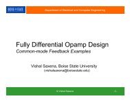
Department of Electrical and Computer Engineering<strong>SpectreRF</strong> <strong>Periodic</strong> <strong>Analysis</strong>Switched capacitor Circuit Simulation© Vishal Saxena -1-
AgendaSampled data systemsBrief explanation and usage of PAC/PXF analyses in<strong>SpectreRF</strong>PNOISE <strong>Analysis</strong>Simulation Examples• Simple S/H• Switch capacitor buffer• T/R© Vishal Saxena -2-
<strong>SpectreRF</strong> AnalysesPSS – <strong>Periodic</strong> Steady State <strong>Analysis</strong>PAC – <strong>Periodic</strong> AC <strong>Analysis</strong>PSTB – <strong>Periodic</strong> Stability <strong>Analysis</strong>PXF – <strong>Periodic</strong> Transfer FunctionPNoise – <strong>Periodic</strong> Noise <strong>Analysis</strong>PDist – <strong>Periodic</strong> Harmonic Distortion <strong>Analysis</strong>QPSS?© Vishal Saxena -3-
PSS <strong>Analysis</strong> <strong>Periodic</strong> Steady-State <strong>Analysis</strong> PSS calculates the period operating point• Required for other small-signal analyses (PAC, PXF, PNoise)• Only clock is applied, transient input disabled PSS Cadence parameters• harmonics specifies requested output harmonics to be viewed• maxacfreq is an accuracy parameter that specifies the maximumfrequency that will be used in any subsequent small-signal analyses(4xharmonics by default)• Recommended formula:• fstop is maximum frequency of PAC/PXF/etc. sweep range• maxsideband specified in PAC/PXF/etc.• fs is clock frequency© Vishal Saxena -4-
<strong>SpectreRF</strong> <strong>Analysis</strong> Forms© Vishal Saxena -5-
PAC <strong>Analysis</strong> <strong>Periodic</strong> AC <strong>Analysis</strong> PAC “computes the output signal at every node and everysideband given a single input”1• Creates a mapping between an input freq range and each resultingoutput freq range due to modulation• Use PAC to find how an interesting input frequency is modulatedand attenuated to resulting frequencies at the output PAC Cadence parameters• Specified sweep frequency is the INPUT frequency range• maxsideband determines the number of output frequency bandscalculated by Cadence to which the input range is modulated• Set pacmagnitude in source to 1V• Can choose any circuit node as PAC output© Vishal Saxena -6-
PAC <strong>Analysis</strong> Sweeping PAC input frequency from 0 fs/2 shows the modulation ofthe input signal baseband into all of the specified output bands…perfect for nyquist band limited input signals Sweeping past fs/2 shows the modulation of higher input signal bandsinto all of the specified output bands© Vishal Saxena -7-
PXF <strong>Analysis</strong> <strong>Periodic</strong> Transfer Function <strong>Analysis</strong> PXF “computes the transfer function from every inputsource at every sideband to a single output”1• Creates mapping between a particular output frequency and thecombination of modulated input frequencies that compose it• Use PXF to find the input frequency composition of an interestingoutput frequency PXF Cadence parameters• Specified sweep frequency is the OUTPUT frequency range• maxsideband specifies the number of input frequency bandscalculated by Cadence that are modulated into the output frequencyrange• Set specific output node in analysis form• Can choose any source in the circuit to view XF to the output© Vishal Saxena -8-
PXF <strong>Analysis</strong> Sweeping PXF from 0 fs/2 shows how all of the chosen inputfrequency bands modulate into the output baseband Each color curve segment represents the output baseband where thestarting harmonic is DC© Vishal Saxena -9-
PXF <strong>Analysis</strong>‣ Sweeping PXF past fs/2 shows how the specified input frequencybands modulate into higher output bands© Vishal Saxena -10-
Comment About PAC/PXF Sweep Type Previous results have been plotted for linear sweeps Logarithmic sweeps refer all waveforms into frequency sweep range:• PAC – all output sidebands are shown as folded into the input frequencysweep range. Output signal frequency information not shown.• PXF – input sideband contributions are folded into output frequency sweeprange. Information relating contributions to input frequencies not shown. Example: PAC linear sweep (left), log sweep (right, changed to linaxis)© Vishal Saxena -11-
PXF vs PACPACI know my input signal, how does this become my outputsignal?PXFI know my output signal, how does this come from my inputsignal?© Vishal Saxena -12-
<strong>SpectreRF</strong> PAC/PXF <strong>Analysis</strong> Forms© Vishal Saxena -13-
PNOISE <strong>Analysis</strong>Simulation of noise in sampled circuitsExample: Switch-C circuit• Here an NMOS switch with C=1pF, f clk =10MHzSet up PSS analysis for the f clk =10MHz clock© Vishal Saxena © Vishal and Saxena Venkatesh Acharya -14-
PNOISE <strong>Analysis</strong>Include sufficient number of maxsideband for accuracy© Vishal Saxena -15-© Vishal Saxena and Venkatesh Acharya 15
PNOISE <strong>Analysis</strong>Simulation shows 89μV of output RMS noise• Ideal √(kT/C) value =64μV,• Simulation results close to the approximation of √(kT/C)© Vishal Saxena -16-© Vishal Saxena and Venkatesh Acharya 16
PNOISE <strong>Analysis</strong>Accuracy is tightened by using large number of maxsidebandparameter• Determines how many sideband alias into the given band• Trades-off simulation time with accuracyFor analytical details, refer to:http://www.designers-guide.org/analysis/sc-filters.<strong>pdf</strong>© Vishal Saxena -17-© Vishal Saxena and Venkatesh Acharya 17
Sampled Signal <strong>Analysis</strong>• A Sample and hold (S/H) is analyzed in the time domain as an idealsampler in cascade with a zero-order hold (ZOH)vSH vS* ZOH vAvD*ZOHv Av Dv SZOHv SH• The ideally sampled signal v S (t) is obtained by multiplying input withperiodic pulse trainvt t DkT skv A (t)v D (t) (t)x =v S (t)-T sT s2T s 3T s 4T s© Vishal Saxena -18-
Sampled Signal <strong>Analysis</strong>• The frequency spectrum of the impulse train is found from the fouriertransform of the fourier series representation1svDs D sTjn2ftt t kT e V f f f nf knsns• Multiplying with pulse train in time domain convolving with pulsetrain in frequency domain1fsT| V A f || f |fs* =f sV D| f |fsf s 2 fs3 fsV Sfss2 fsfsVA f © Vishal Saxena -19-
Sampled Signal <strong>Analysis</strong>• The S/H output is found by convolving v S (t) with the cascaded ZOHimpulse response (a unit pulse, a fraction of the sampling period)v S (t)fsfsVA f 2 fs*x =ZOHv S (t)| V S f || f |1ZOH | f | f TTs• Convolving with ZOH in time domain multiplying with sinc infrequency domainT mT msT ssincmffs= V SHv SH (t)© Vishal Saxena -20-f s
Sampled Signal <strong>Analysis</strong>• Result is the baseband filtered by the sinc main lobe, plus frequencyperiodic baseband replicas filtered by the sinc side lobesVSH f mT sinc mf V f nf msincm V f nf sffsnss• Shape of sinc function (and filtering of spectrum) depends on S/Hduty cycle (m)• m
Sampled Signal <strong>Analysis</strong> Sampling into the digital domain (A/D converter) acts as an ideally sampledsystem and replicates the spectrum at all clock harmonics Any spectrum energy outside of the Nyquist range gets folded/aliased intobaseband SNR need be considered only within f=0fs/2 because spectrum is symmetricabout DC and repeats every fs (DTFT)© Vishal Saxena -22-
PXF/PAC Analyses for Basic Applications Ideal Sample and Hold (S/H) RC Band-limited S/H Switch Capacitor (SC) Buffer© Vishal Saxena -23-
Ideal Sample and Hold (S/H)V inΦ 1Φ 2V o© Vishal Saxena -24-
Expectation: Ideal S/HV inΦ 1Φ 2V o• Assume a unity, nyquist band-limited input• Like a input band limited AC analysis (like a PAC)| V A f || V D f || f |V S* =f s2fsf sfs2 fs3 fsfs2 fs| V S f || ZOH f || V SH f |x =fs2 fsfs2 fs© Vishal Saxena -25-
PAC: Ideal S/H• Sweep from 0f s /2: only looking at how input basebandmodulates into other bands• AC input is unity over all frequencies, therefore output is the sincshaping of the modulated input basebandV inΦ 1Φ 2V oF clk =100 MHz0 output sidebandPSS beat freq=100M autocalculatedmaxacfreq=default-1+1+2+3 +4-2-3 -4PAC input frequency range(100Hz , f s /2=50MHz),linear sweep, 1000 stepsmaxsideband=4© Vishal Saxena -26-
PXF: Ideal S/H• Sweep from 0f s /2: only looking at how input frequenciesmodulate into the output baseband• Resulting curves only show output baseband shaping (main lobeof sinc)V inΦ 1Φ 2V oF clk =100 MHzPSS beat freq=100M autocalculatedmaxacfreq=default0 -1 +1 -2 +2 -3 +3 -4 +4PXF output frequency range (100,50M)linear sweep, 1000 stepsmaxsideband=4© Vishal Saxena -27-
PAC: RC limited S/HΦ 1V inCΦ 2V o• Baseband input should modulate to output bands similarly to ideal caseif RC constant designed correctly (PAC)• S/H now has limiting bandwidth, so higher input frequencies willattenuate when modulating into output baseband (PXF)• Set 1/RC = 2*pi*f clk *7 => 700 MHz: C=1pF, R~230 ohms, W/L=9u/.18u© Vishal Saxena -28-
PXF: RC limited S/HΦ 1V inCΦ 2V o• Baseband input should modulate to output bands similarly to ideal caseif RC constant designed correctly (PAC)F clk =100 MHzPSS beat freq=100M autocalculatedmaxacfreq=defaultPAC input frequency range(100Hz ,50MHz), f s /2linear sweep, 1000 stepsmaxsideband=4© Vishal Saxena -29-
SC Buffer• Ideal switches, no resistance• Ideal OpAmp, no BW limit• Sinc shaping slightly off due to reductionof duty cycle for non-overlapping phasesZOH f mTssincmffs Φ 1Φ 1Φ 2Φ 2CΦ 1pΦ 2Φ 2Φ 1pΦ 1Φ 1CC© Vishal Saxena -30-
SC Buffer• Ideal switches with resistance• Ideal OpAmp, no BW limitNo ResistanceAdded ResistanceAdding the switch resistance of the SC Buffer: PAC© Vishal Saxena -31-
SC Buffer• Ideal switches with resistance• Ideal OpAmp with limited BWReducing the BW of the SC Buffer OpAmp: PAC (left) PXF (right)© Vishal Saxena -32-
Track and Reset• Ideal track and reset:• Analyzed as input multiplied by pulse train• Result is passband modulated by pulse train tones• No resistance yields no shaping in bands• Pulse train tones off due to non-overlapping clocks• PAC and PXF look identical~1/2~1/pi~1/3pi© Vishal Saxena -33-
Track and Reset• Real track and reset:Φ 1• Added switch resistances (R=1k, C=1p)• Results in shaped, modulated passbands• PAC: modulation from input passband into output sidebands• PXF: modulation from input sidebands into output passbandV inV oΦ 2© Vishal Saxena -34-
Track and Reset• Real track and reset:• Excessive resistance (R=10k, C=1p)© Vishal Saxena -35-
Track and Reset• Real track and reset:• Changing the resistance ratio scales the response• DC and input clk harmonics modulating to outputscaled by 2R 1 R 2 /(R 1 +R 2 ) from ideal• R 1 =10k, R 2 =1k, C=1pV inΦ 1V oΦ 2Harmonics scaleaccording to resistor ratio© Vishal Saxena -36-
References1. <strong>SpectreRF</strong> User Manual2. Josh Carnes and Peter Kurahasi, “<strong>Periodic</strong> Analyses of Sampled SystemsUsing <strong>SpectreRF</strong>”3. K. Kundert, “Simulating Switched-Capacitor Filters with <strong>SpectreRF</strong>,” TheDesigner’s Guide Community, www. http://www.designers-guide.org/, 2005.http://www.designers-guide.org/analysis/sc-filters.<strong>pdf</strong>1. K. Kundert, “An Introduction to Cyclostationary Noise,” The Designer’s GuideCommunity, www. http://www.designers-guide.org/, 2005.2. K. Kundert, “Device Noise Simulation of Delta-Sigma Modulators,” TheDesigner’s Guide Community, www. http://www.designers-guide.org/, 2005.3. C.A. Gobet, “Spectral Distribution of a Sampled 1st-Order Lowpass FilteredWhite Noise,” Electronics Letters, vol. 17, pp. 720-721, Sep. 1981.4. C.A. Gobet, A. Knob, “Noise <strong>Analysis</strong> of Switched Capacitor Networks,” IEEETrans. Circuits and Systems, vol. cas-30, pp. 37-43, Jan. 1983.5. J.H. Fischer, “Noise Sources and Calculation Techniques for SwitchedCapacitor Filters,” IEEE J. Solid-State Circuits, vol. sc-17, pp. 742-752, Aug.1982.© Vishal Saxena -37-