Annals of Warsaw University of Life Sciences - SGGW.
Annals of Warsaw University of Life Sciences - SGGW.
Annals of Warsaw University of Life Sciences - SGGW.

Create successful ePaper yourself
Turn your PDF publications into a flip-book with our unique Google optimized e-Paper software.
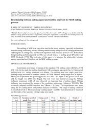
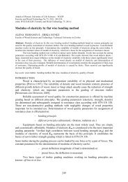
14 G. Viselga, J.R. KamińskiEXPERIMENTAL OBJECTIVETo identify possibilities to reducedeviations <strong>of</strong> straight-line coursemovement and positioning in relation tothe effect <strong>of</strong> micro and macro unevenness<strong>of</strong> the field, by choosing chassis type,control methods and parameters, andto estimate technological and energeticefficiency <strong>of</strong> the model.EXPERIMENTAL METHODSThe course <strong>of</strong> the positioned gantrymodule (PGM) is maintained by alaser instrument UKL – 1 (УКЛ – 1).A laser beam generator emitting avertical beam is placed at the end <strong>of</strong> theexperimental field. A laser beam catcherwith photo diodes is mounted on a PGMreplaceable support (Fig. 1). When themodule deviates from the course, laserbeam is passed into one <strong>of</strong> the marginalphotodiodes and a signal is formed, whichis passed into the control panel. Thecontrol panel switches <strong>of</strong>f transmitter <strong>of</strong>one or the other chassis and when PGMspar turns perpendicularly to the straightlinecourse, the transmitter <strong>of</strong> the chassisis turned on again.PGM is positioned by a specialpositioning trundle. It is run by a 12 Velectric motor through a worm self--braking reduction gear.When positioning trundle is running,a horizontal round tube inertly joinedwith it, moves along the bracket withterminal switches. When running, PGMbracket with terminal switches movesalong the tube <strong>of</strong> stopped positioningtrundle. Having moved on motionlimiters, the terminal switch <strong>of</strong> theFIGURE 1. Technological scheme <strong>of</strong> PGM: 1 – spar; 2 – chassis; 3 – working parts stretcher; 4 – rope<strong>of</strong> working parts stretcher; 5 – working parts; 6 – working parts fixing carriage; 7 –axis <strong>of</strong> turning <strong>of</strong>working parts; 8 – back disconnectors with the switchover contact; 9 – flexible cable; 10 – cable drum;11 – horizontal tube with motion limiters; 12 – laser catcher with photodiodes; 13 – positioning trundle;14 – motor <strong>of</strong> working parts stretcher; A – distance between centres <strong>of</strong> photodiodes; B – distance <strong>of</strong>catcher’s photodiodes to the spar (B = 1 m); C – catcher’s distance from a wheel positioned the chassis;l s – spar length (l s = 18 m)