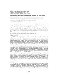
18 G. Viselga, J.R. Kamińskichassis positioned according to the bend<strong>of</strong> the spar were by on average 1.6––2.1 times higher due to differences intramline unevenness.The distance between photodiodes,when A = 20–30 mm did not have anysignificant effect on the positioningprecision <strong>of</strong> the right chassis positionedby a trundle. Mean deviations rangedbetween 62–64 mm, and mean squaredeviations amounted to 19–26 mm, meandeviations <strong>of</strong> the other chassis rangedwithin wider limits <strong>of</strong> 29–63 mm, andmean square deviation when increasingthe distance between photodiodes from50 to 67 mm, increased by 1.3 times,from 81 to 104 mm.On the basis <strong>of</strong> the above-mentioneddata we can find that positioning speedis a decisive factor for positioningprecision. With increasing speed, inertiaforces increase when stopping or startingduring positioning, which increasespositioning deviations.Variation <strong>of</strong> asynchronous motorspower <strong>of</strong> electromechanical transmitteris rather typical (Fig. 5a). Duringpositioning, the power depended onthe speed <strong>of</strong> chassis. During automaticactuation <strong>of</strong> chassis motors the powerslightly exceeded the mean value. At0.083 m/s speed <strong>of</strong> chassis the powerinappreciably fluctuated and amountedto on average 0.08 kW. During the coursecorrections when motors temporarilyswitched <strong>of</strong>f, the power declined to zero.Duration <strong>of</strong> corrections was about 0.8––1.0 s. The power <strong>of</strong> individual motors<strong>of</strong> chassis slightly differed, most likelydue to the different distances coveredduring skid.Motor power <strong>of</strong> electromechanicaltransmitter <strong>of</strong> rope stretcher <strong>of</strong> implementcarriage at actuation moments wasat its peak, up to 4.8 kW, and duringstabilisation <strong>of</strong> implement tractionresistance, declined to 0.74 kW. Thelength <strong>of</strong> peak was 0.8–1.2 s. Due tothese power peaks, the working width <strong>of</strong>the implements was limited.An increase in positioning speed<strong>of</strong> PGM with an electromechanicaltransmitter to over 0.1 m/s wascomplicated due to the impacts duringtransitional processes.Comparison <strong>of</strong> power utilisationgraphs presented in Figure 5 suggeststhat chassis speeds in the case <strong>of</strong>electromechanical transmitter were4.7 times lower, and the power <strong>of</strong>chassis differed by 3.7 times, i.e. withincreasing speed the power increasesless. Implement speeds in the case <strong>of</strong>hydromechanical transmitter were by1.76 times higher, and the power 3times higher compared with implementcarriage pulling using electromechanicaltransmitter. This increase in poweroccurred due to the flow in throttletransmitter. When throttling is reduced,i.e. when revolution frequency is reducedby a mechanical transmitter, the powerdoes not increase significantly.Low power requirement <strong>of</strong> chassisenables to position chassis even bya muscle power <strong>of</strong> man. The power <strong>of</strong>implement carriage stretcher is higherand increases with increasing the workingwidth <strong>of</strong> implements. The total requiredpower can be fully generated bysolar energy photoconverters, havingmounted over the spar and chassis. Thearea <strong>of</strong> PGM cover fitted up from thephotoconverters l s × 2b would be 80–100m 2 for 20 m long spar and would protectPGM mechanism from precipitation. In
Precision and energy parameters <strong>of</strong> the positioned gantry module 194,0N, kWN max =4,77kW3,53,0positioningN=N k +N dWork <strong>of</strong> implement carriageN=N padpositioningN=N k +N d2,5a)2,01,5implement <strong>of</strong> carriage (P pv) N pad )left <strong>of</strong> left chassis chassis (N k) (P k)right <strong>of</strong> right chassis chassis (Nd)(P d)totaltotalpower(P)(N)correctioncorrection1,00,50,00 10 20 30 40 t, s 507,0N, kW6,0positioningwork <strong>of</strong> implement carriagepositioningwork <strong>of</strong> implement carriage5,04,0b)3,02,01,0correctioncorrection0,0130 135 140 145 150 155 t, s 160a – in electromechanical transmitter (mean parameters: v chas. = 0,083 m/s N važ = 0,89 kW, v pad = 0,57 m/s,N pad = 0,74 kW)b – in hydromechanical transmitter (v chas. = 0,390 m/s, N chas. = 3,29 kW, v impl. = 1,00 m/s, N impl. = 2,21 kW,intensity <strong>of</strong> corrections –3)FIGURE 5. Power variation fragment <strong>of</strong> asynchronous motorsthe long run, it is more viable to use theenergy <strong>of</strong> chemical fuel converters forPGM or to combine it with the use <strong>of</strong> solarenergy.For the calculation <strong>of</strong> energy input,it is necessary to estimate the capacitiesand power <strong>of</strong> implements W impl. andchassis W chas :W impl. = 0.36 l s B p /t p , == 0.36 B p v impl. , ha/h (1)W chas. = 0,36q/t == 0,36 l p v chas. , ha/h (2)where: l p – positioning distance, m.Since we cannot add these capacitiesor calculate their average, to find totalPGM capacity we have to calculateworking time input per ha <strong>of</strong> implementsand positioning and to add it. Total PGMlabour efficiency is calculated as aninverse value <strong>of</strong> total working time input.
- Page 1: Annalsof WarsawUniversityof LifeSci
- Page 7 and 8: Inveatigations on soil conservation
- Page 9 and 10: Inveatigations on soil conservation
- Page 11 and 12: Inveatigations on soil conservation
- Page 13 and 14: Annals of Warsaw University of Life
- Page 15 and 16: Precision and energy parameters of
- Page 17: Precision and energy parameters of
- Page 21: Precision and energy parameters of
- Page 24 and 25: 24 A. Lisowski et al.62.8, 59.4 and
- Page 26 and 27: 26 A. Lisowski et al.TABLE 2. Param
- Page 28 and 29: 28 A. Lisowski et al.in three and t
- Page 30 and 31: 30 A. Lisowski et al.według normy
- Page 33: Economic effi ciency of growing and
- Page 36 and 37: 36 J. Jánský, I. ŽivělováTABLE
- Page 39 and 40: Annals of Warsaw University of Life
- Page 41 and 42: Effect of storage conditions on bio
- Page 43 and 44: Effect of storage conditions on bio
- Page 45 and 46: Annals of Warsaw University of Life
- Page 47 and 48: Investigations on drying of new pum
- Page 49 and 50: Investigations on drying of new pum
- Page 51 and 52: Annals of Warsaw University of Life
- Page 53 and 54: Analysis of optimal values of air s
- Page 55 and 56: Analysis of optimal values of air s
- Page 57: Analysis of optimal values of air s
- Page 60 and 61: 60 M. Klimkiewicz- units and parts
- Page 62 and 63: 62 M. Klimkiewiczwhere: S(x l,…,
- Page 64 and 65: 64 M. KlimkiewiczTABLE 5. Matrix of
- Page 67 and 68: Annals of Warsaw University of Life
- Page 69 and 70:
Properties and structure of spheroi
- Page 71:
Properties and structure of spheroi
- Page 74 and 75:
74 G. Elmasry, N. Wang, C. Vigneaul
- Page 76 and 77:
76 G. Elmasry, N. Wang, C. Vigneaul
- Page 78 and 79:
78 G. Elmasry, N. Wang, C. Vigneaul
- Page 81 and 82:
Annals of Warsaw University of Life
- Page 83 and 84:
Hyperspectral imaging for chilling
- Page 85 and 86:
Hyperspectral imaging for chilling
- Page 87 and 88:
Hyperspectral imaging for chilling
- Page 89 and 90:
Annals of Warsaw University of Life
- Page 91 and 92:
Experimental verifying of mathemati
- Page 93:
Experimental verifying of mathemati
- Page 96 and 97:
96 J. Kára, Z. Pastorek, R. Adamov
- Page 98 and 99:
98 J. Kára, Z. Pastorek, R. Adamov
- Page 100 and 101:
100 J. Kára, Z. Pastorek, R. Adamo
- Page 103 and 104:
Annals of Warsaw University of Life
- Page 105 and 106:
New fermentation source in the tech
- Page 107 and 108:
Annals of Warsaw University of Life
- Page 109 and 110:
Agricultural business extension aid
- Page 111 and 112:
Agricultural business extension aid
- Page 113 and 114:
Agricultural business extension aid