

Nonvolatile, I2C-Compatible 64-Position, Digital Potentiometer ...
Nonvolatile, I2C-Compatible 64-Position, Digital Potentiometer ...
Nonvolatile, I2C-Compatible 64-Position, Digital Potentiometer ...

You also want an ePaper? Increase the reach of your titles
YUMPU automatically turns print PDFs into web optimized ePapers that Google loves.
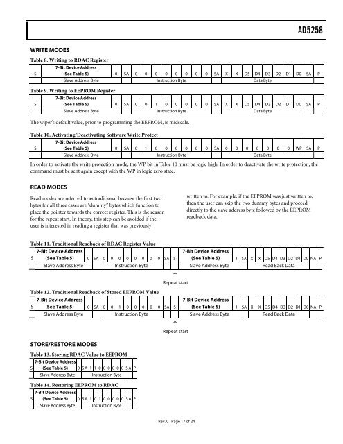
AD5258WRITE MODESTable 8. Writing to RDAC RegisterS7-Bit Device Address(See Table 5) 0 SA 0 0 0 0 0 0 0 0 SA X X D5 D4 D3 D2 D1 D0 SA PSlave Address Byte Instruction Byte Data ByteTable 9. Writing to EEPROM RegisterS7-Bit Device Address(See Table 5) 0 SA 0 0 1 0 0 0 0 0 SA X X D5 D4 D3 D2 D1 D0 SA PSlave Address Byte Instruction Byte Data ByteThe wiper’s default value, prior to programming the EEPROM, is midscale.Table 10. Activating/Deactivating Software Write ProtectS7-Bit Device Address(See Table 5) 0 SA 0 1 0 0 0 0 0 0 SA 0 0 0 0 0 0 0 WP SA PSlave Address Byte Instruction Byte Data ByteIn order to activate the write protection mode, the WP bit in Table 10 must be logic high. In order to deactivate the write protection, thecommand must be sent again except with the WP in logic zero state.READ MODESRead modes are referred to as traditional because the first twobytes for all three cases are “dummy” bytes which function toplace the pointer towards the correct register. This is the reasonfor the repeat start. In theory, this step can be avoided if theuser is interested in reading a register that was previouslywritten to. For example, if the EEPROM was just written to,then the user can skip the two dummy bytes and proceeddirectly to the slave address byte followed by the EEPROMreadback data.Table 11. Traditional Readback of RDAC Register Value7-Bit Device AddressS (See Table 5) 0 SA 0 0 0 0 0 0 0 0 SA S7-Bit Device Address(See Table 5) 1 SA X X D5 D4 D3 D2 D1 D0 NA PSlave Address Byte Instruction Byte Slave Address Byte Read Back Data↑Repeat startTable 12. Traditional Readback of Stored EEPROM Value7-Bit Device AddressS (See Table 5) 0 SA 0 0 1 0 0 0 0 0 SA S7-Bit Device Address(See Table 5) 1 SA X X D5 D4 D3 D2 D1 D0 NA PSlave Address Byte Instruction Byte Slave Address Byte Read Back Data↑Repeat startSTORE/RESTORE MODESTable 13. Storing RDAC Value to EEPROM7-Bit Device AddressS (See Table 5) 0 SA 1 1 0 0 0 0 0 0 SA PSlave Address Byte Instruction ByteTable 14. Restoring EEPROM to RDAC7-Bit Device AddressS (See Table 5) 0 SA 1 0 1 0 0 0 0 0 SA PSlave Address Byte Instruction ByteRev. 0 | Page 17 of 24

![P-CAD EDA - [Sheet1]](https://img.yumpu.com/49470492/1/190x115/p-cad-eda-sheet1.jpg?quality=85)


