

Nonvolatile, I2C-Compatible 64-Position, Digital Potentiometer ...
Nonvolatile, I2C-Compatible 64-Position, Digital Potentiometer ...
Nonvolatile, I2C-Compatible 64-Position, Digital Potentiometer ...

Create successful ePaper yourself
Turn your PDF publications into a flip-book with our unique Google optimized e-Paper software.
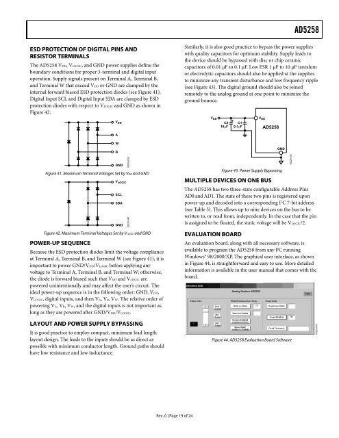
AD5258ESD PROTECTION OF DIGITAL PINS ANDRESISTOR TERMINALSThe AD5258 VDD, VLOGIC, and GND power supplies define theboundary conditions for proper 3-terminal and digital inputoperation. Supply signals present on Terminal A, Terminal B,and Terminal W that exceed VDD or GND are clamped by theinternal forward biased ESD protection diodes (see Figure 41).<strong>Digital</strong> Input SCL and <strong>Digital</strong> Input SDA are clamped by ESDprotection diodes with respect to VLOGIC and GND as shown inFigure 42.V DDSimilarly, it is also good practice to bypass the power supplieswith quality capacitors for optimum stability. Supply leads tothe device should be bypassed with disc or chip ceramiccapacitors of 0.01 µF to 0.1 µF. Low ESR 1 µF to 10 µF tantalumor electrolytic capacitors should also be applied at the suppliesto minimize any transient disturbance and low frequency ripple(see Figure 43). The digital ground should also be joinedremotely to the analog ground at one point to minimize theground bounce.V DDC210µF+C10.1µFV DDAD5258AWBGNDFigure 41. Maximum Terminal Voltages Set by VDD and GNDV LOGICSCLSDAGNDFigure 42. Maximum Terminal Voltages Set by VLOGIC and GNDPOWER-UP SEQUENCEBecause the ESD protection diodes limit the voltage complianceat Terminal A, Terminal B, and Terminal W (see Figure 41), it isimportant to power GND/VDD/VLOGIC before applying anyvoltage to Terminal A, Terminal B, and Terminal W; otherwise,the diode is forward biased such that VDD and VLOGIC arepowered unintentionally and may affect the user’s circuit. Theideal power-up sequence is in the following order: GND, VDD,VLOGIC, digital inputs, and then VA, VB, VW. The relative order ofpowering VA, VB, VW, and the digital inputs is not important aslong as they are powered after GND/VDD/VLOGIC.05029-03905029-040GNDFigure 43. Power Supply BypassingMULTIPLE DEVICES ON ONE BUSThe AD5258 has two three-state configurable Address PinsAD0 and AD1. The state of these two pins is registered uponpower-up and decoded into a corresponding I 2 C 7-bit address(see Table 5). This allows up to nine devices on the bus to bewritten to, or read from, independently. In the case that the pinis assigned to be floated, the static voltage will be VLOGIC/2.EVALUATION BOARDAn evaluation board, along with all necessary software, isavailable to program the AD5258 from any PC runningWindows® 98/2000/XP. The graphical user interface, as shownin Figure 44, is straightforward and easy to use. More detailedinformation is available in the user manual that comes with theboard.05029-041LAYOUT AND POWER SUPPLY BYPASSINGIt is good practice to employ compact, minimum lead lengthlayout design. The leads to the inputs should be as direct aspossible with minimum conductor length. Ground paths shouldhave low resistance and low inductance.Figure 44. AD5258 Evaluation Board Software05029-042Rev. 0 | Page 19 of 24

![P-CAD EDA - [Sheet1]](https://img.yumpu.com/49470492/1/190x115/p-cad-eda-sheet1.jpg?quality=85)


