SR99 Bored Tunnel-Assessment of Settlement Impacts ... - SCATnow
SR99 Bored Tunnel-Assessment of Settlement Impacts ... - SCATnow
SR99 Bored Tunnel-Assessment of Settlement Impacts ... - SCATnow

You also want an ePaper? Increase the reach of your titles
YUMPU automatically turns print PDFs into web optimized ePapers that Google loves.
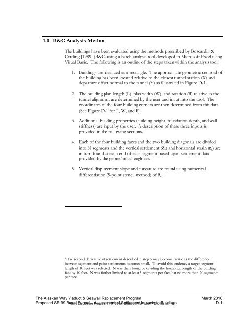
1.0 B&C Analysis MethodThe buildings have been evaluated using the methods prescribed by Boscardin &Cording [1989] (B&C) using a batch analysis tool developed in Micros<strong>of</strong>t Excel usingVisual Basic. The following is an outline <strong>of</strong> the steps taken within the analysis tool:1. Buildings are idealized as a rectangle. The approximate geometric centroid <strong>of</strong>the building has been located relative to the closest tunnel station (X) anddeparture <strong>of</strong>fset normal to the tunnel (Y) as illustrated in Figure D-1.2. The building plan length (L), plan width (W), and rotation (θ) relative to thetunnel alignment are determined by the user and input into the tool. Thecoordinates <strong>of</strong> the four building corners are then determined from this data(See Figure D-1 for L, W, and θ).3. Additional building properties (building height, foundation depth, and wallstiffness) are input by the user. A description <strong>of</strong> these three inputs isprovided in the following sections.4. Each <strong>of</strong> the four building faces and the two building diagonals are dividedinto N segments and the vertical settlement (δ v ) and horizontal strain (ε h ) arein turn found at each end <strong>of</strong> each segment based upon settlement dataprovided by the geotechnical engineer. 15. Vertical displacement slope and curvature are found using numericaldifferentiation (5-point stencil method) <strong>of</strong> δ v .1 The second derivative <strong>of</strong> settlement described in step 5 may become erratic as the differencebetween segment end point settlements becomes small. To avoid this tendency a target segmentlength <strong>of</strong> 10 feet was selected. N was then found by dividing the horizontal length <strong>of</strong> the buildingface by 10 feet. N was further limited to at least 5 segments per face but no more than 20 segmentsper face.The Alaskan Way Viaduct & Seawall Replacement Program March 2010Proposed SR 99 <strong>Bored</strong> <strong>Tunnel</strong> - <strong>Assessment</strong> <strong>of</strong> <strong>Settlement</strong> <strong>Impacts</strong> to Buildings D-1Public Disclosure Request 11-0123 for Elizabeth Campbell - 2nd installment