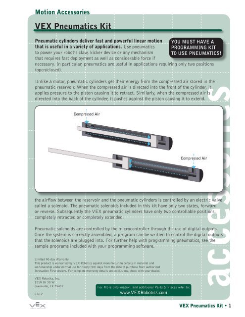
VEX Pneumatics Kit - VEX Robotics
VEX Pneumatics Kit - VEX Robotics
VEX Pneumatics Kit - VEX Robotics
- No tags were found...

You also want an ePaper? Increase the reach of your titles
YUMPU automatically turns print PDFs into web optimized ePapers that Google loves.
Motion Accessories<strong>VEX</strong> <strong>Pneumatics</strong> <strong>Kit</strong> (continued)Section 1: Component Assembly Instructions1. Remove the protective seals fromthe reservoir openings and installthe reservoir fitting and reservoirtire pump fitting as shown usinga standard 7/16-inch wrench. Toensure a proper seal, tighten thefitting until all of the thread tapeis hidden from view.2. Install the flow control fitting and brass cylinderfitting in each cylinder as shown. Using a smallpair of pliers, carefully tighten the fitting toapproximately ¼ turn past finger-tight.3. Install the rod pivot on the cylinder rod as shownusing (2) 6-40 nuts. To secure the cylinder rodpivot, tighten the mounting nuts using a 5/16-inch wrench.4. Install the cylindermount on the backof the cylinderas shown usinga <strong>VEX</strong> standard1-inch long 8-32screw and 8-32nylock nut.accessories<strong>VEX</strong> <strong>Pneumatics</strong> <strong>Kit</strong> • 2
Motion Accessories<strong>VEX</strong> <strong>Pneumatics</strong> <strong>Kit</strong> (continued)5. Install a solenoid fitting into the center hole onthe bottom of the solenoid. Tighten the fitting toapproximately ¼ turn past finger-tight.6. Install two more solenoid fittings into the holesmarked A and B on the top of the solenoid. Tighten thefittings to approximately ¼ turn past finger-tight.7. Plug the solenoid drive cable into the solenoid asshown. Note that the connector is keyed to prevent itfrom being plugged in the wrong way.accessories<strong>VEX</strong> <strong>Pneumatics</strong> <strong>Kit</strong> • 3
Motion Accessories<strong>VEX</strong> <strong>Pneumatics</strong> <strong>Kit</strong> (continued)Section 2: Assembling the SystemPneumatic TubingIncluded in this kit is 5 feet of 4mm OD pneumatic tubing. This tubing serves as the pipingwhich carries air throughout the system. In order to assemble a complete system, the tubingwill need to be cut to the specific lengths that you need. A pair of scissors or a small pair ofwire cutters works well for this.When cutting a length of tubing, it is always a good idea to cut each section slightly longerthan necessary. A tube that is overly tight or kinked could cause the system to leak.Please note: It is very important to cut the tubingcleanly and perpendicular to its length. A crookedor jagged cut will lead to air leaks in the system.To connect the individual components in thesystem, simply insert the tubing into the onetouchvalues. To remove a tube from the onetouchvalve, hold down the plastic button that surroundsthe valve entrance as you pull the tube out.accessoriesSolenoid ValveAfter mounting one-touch fittings into the ports labeled P, A and B on the solenoid (seeSection 1 for instructions), it can be installed into the pneumatic system. The hose connectedto port P on the bottom of the solenoid should lead back to the pneumatic reservoir.Ports A and B on the solenoid should be connected to the two fitting on the pneumaticcylinder. While it is not necessary to connect port A or B to a specific fitting on the cylinder,reversing these connections is a good way to invert the default state of the cylinder. Thesolenoid will open port B by default, meaning that the cylinder fitting connected to this portwill receive pressure when the digital output is set to low or the robot is turned off.Note: A way to conserve pressure in your pneumatic system is to mount the solenoid as closeas possible to the cylinder. Excess tubing between the solenoid and the cylinder will causeyour system to loose more pressure with each stroke.<strong>VEX</strong> <strong>Pneumatics</strong> <strong>Kit</strong> • 4
Motion Accessories<strong>VEX</strong> <strong>Pneumatics</strong> <strong>Kit</strong> (continued)Tire Pump FittingOne of the reservoir fittings is equipped with a schrader valvethat will be used to charge the pneumatic system. This fittingcan be used with any standard bike pump or air compressor.Note: The maximum recommended input pressure for the<strong>VEX</strong> Pneumatic System is 100 psi (0.7 MPa). Chargingyour system to a greater pressure is considered unsafe andis not legal for <strong>VEX</strong> <strong>Robotics</strong> Competition use. To preventovercharging, we recommend using a quality bike pump thatis equipped with a pressure gauge.accessoriesPressure RegulatorThe pressure regulator allows you to adjust the maximum amount of pressure that will reachthe cylinders. While the pressure regulator is not a necessary component in every pneumaticsystem, it is useful in applications that do not require the cylinder’s full force. Also, byreducing the applied pressure to the cylinders, you can conserve pressure and equalizeperformance in the pneumatic system.The pressure regulator must be installed so that the hose connected to the blue one-touchfitting leads to the cylinders and the hose connected to the brass connector leads to thereservoir.When correctly installed, turningthe adjustment screw on thepressure regulator to the left(unscrewing) will decrease themaximum amount of pressure thatreaches the cylinders. Turningthe adjustment screw to the right(screwing in) will increase themaximum amount of pressurethat reaches the cylinders thusincreasing their initial performancebut using more pressure for eachstroke. Turning the adjustmentscrew all the way to the right (allthe way in) will completely openthe valve and allow the full systempressure to reach the cylinders.Output ToCylindersInput FromReservoirMore PressureLess Pressure<strong>VEX</strong> <strong>Pneumatics</strong> <strong>Kit</strong> • 5
Motion Accessories<strong>VEX</strong> <strong>Pneumatics</strong> <strong>Kit</strong> (continued)Manual On/Off SwitchThe manual On/Off switch is a simple value that allows you to close off pressure to thecylinders without emptying the entire system of air pressure. This is useful if you need thecylinders to temporarily move freely in order to remove a game object or fix a mechanism.Please note the switch must be installed in a specific orientation. The pneumatic hose comingfrom the reservoir should be connected to the fitting with the arrow on it (the arrow shouldface away from the reservoir).Note: When the switch is closed pressure is released from the Output Side.Output To CylindersSwitch OpenOutput SidePressure ReleasedInput From ReservoirSwitch ClosedaccessoriesInput From Reservoir(Flow Blocked)<strong>VEX</strong> <strong>Pneumatics</strong> <strong>Kit</strong> • 6
Motion Accessories<strong>VEX</strong> <strong>Pneumatics</strong> <strong>Kit</strong> (continued)Complete SystemA complete pneumatic system using two cylinders is shown below. A single pneumatic systemcan supply air to any number of cylinders. However, using additional cylinders will cause yoursystem to loose pressure more quickly. In general we do not recommend using more than twocylinders for each reservoir in your system. If you have an application that requires morethan two cylinders, it may be necessary install an additional reservoir. The T-fitting which isincluded in this kit can be used to supply pressure to additional components in your system.accessories<strong>VEX</strong> <strong>Pneumatics</strong> <strong>Kit</strong> • 7
Motion Accessories<strong>VEX</strong> <strong>Pneumatics</strong> <strong>Kit</strong> (continued)Section 3: System DetailsReservoir Specifications:Length7.87 in (20 cm)Diameter1.57 in (4 cm)CylinderWall 0.125 in (3.2 mm)Weight 0.68 lbs (308 g)Volume5.07 fl oz (150 ml)Cylinder Strokes45 Strokes from 100 psi to 25 psiCylinder Specifications:Compressed Length 5.5 in (13.97 cm)Stroke2 in (5.08 cm)Cylinder Bore0.39 in (10 mm)Weight 0.09 lbs (20 g)Maximum Pressure 100 psi (0.7 MPa)Maximum Output Force 12 lbs (54 N)The equation for calculating the Output Force for a specific pressure is given as:(Cross Sectional Area of Cylinder) x (Internal Air Pressure) = ForceaccessoriesThe cylinders bore of the <strong>VEX</strong> Pneumatic Cylinders is .39 in (10 mm). From this we cancalculate the cross sectional area of the cylinder by using the equation for the area of a circle:(Diameter / 2)² x Pi = AreaAs we are given the cylinder bore (inside diameter) and we know that Pi ≈ 3.14, we cancalculate the area to be:(.39 in / 2)² x 3.14 = .12 in²We can now plug this number into our original equation and calculate the cylinder outputforce:.12 in² x 100 psi = 12 Pounds of Force (at 100 psi)<strong>VEX</strong> <strong>Pneumatics</strong> <strong>Kit</strong> • 8