Burr And Stress-Free Cutting Of Flexible Printed Circuits - OnBoard ...
Burr And Stress-Free Cutting Of Flexible Printed Circuits - OnBoard ...
Burr And Stress-Free Cutting Of Flexible Printed Circuits - OnBoard ...

You also want an ePaper? Increase the reach of your titles
YUMPU automatically turns print PDFs into web optimized ePapers that Google loves.
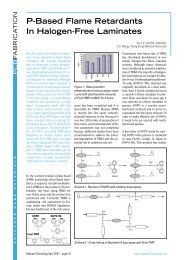
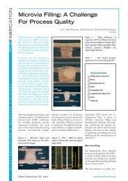
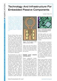
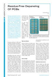
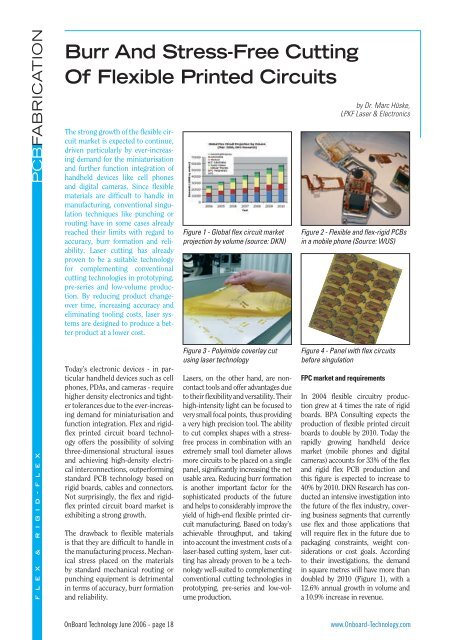
PCBFABRICATION<strong>Burr</strong> <strong>And</strong> <strong>Stress</strong>-<strong>Free</strong> <strong>Cutting</strong><strong>Of</strong> <strong>Flexible</strong> <strong>Printed</strong> <strong>Circuits</strong>The strong growth of the flexible circuitmarket is expected to continue,driven particularly by ever-increasingdemand for the miniaturisationand further function integration ofhandheld devices like cell phonesand digital cameras. Since flexiblematerials are difficult to handle inmanufacturing, conventional singulationtechniques like punching orrouting have in some cases alreadyreached their limits with regard toaccuracy, burr formation and reliability.Laser cutting has alreadyproven to be a suitable technologyfor complementing conventionalcutting technologies in prototyping,pre-series and low-volume production.By reducing product changeovertime, increasing accuracy andeliminating tooling costs, laser systemsare designed to produce a betterproduct at a lower cost.Figure 1 - Global flex circuit marketprojection by volume (source: DKN)by Dr. Marc Hüske,LPKF Laser & ElectronicsFigure 2 - <strong>Flexible</strong> and flex-rigid PCBsin a mobile phone (Source: WUS)F L E X & R I G I D - F L E XToday’s electronic devices - in particularhandheld devices such as cellphones, PDAs, and cameras - requirehigher density electronics and tightertolerances due to the ever-increasingdemand for miniaturisation andfunction integration. Flex and rigidflexprinted circuit board technologyoffers the possibility of solvingthree-dimensional structural issuesand achieving high-density electricalinterconnections, outperformingstandard PCB technology based onrigid boards, cables and connectors.Not surprisingly, the flex and rigidflexprinted circuit board market isexhibiting a strong growth.The drawback to flexible materialsis that they are difficult to handle inthe manufacturing process. Mechanicalstress placed on the materialsby standard mechanical routing orpunching equipment is detrimentalin terms of accuracy, burr formationand reliability.Figure 3 - Polyimide coverlay cutusing laser technologyLasers, on the other hand, are noncontacttools and offer advantages dueto their flexibility and versatility. Theirhigh-intensity light can be focused tovery small focal points, thus providinga very high precision tool. The abilityto cut complex shapes with a stressfreeprocess in combination with anextremely small tool diameter allowsmore circuits to be placed on a singlepanel, significantly increasing the netusable area. Reducing burr formationis another important factor for thesophisticated products of the futureand helps to considerably improve theyield of high-end flexible printed circuitmanufacturing. Based on today’sachievable throughput, and takinginto account the investment costs of alaser-based cutting system, laser cuttinghas already proven to be a technologywell-suited to complementingconventional cutting technologies inprototyping, pre-series and low-volumeproduction.Figure 4 - Panel with flex circuitsbefore singulationFPC market and requirementsIn 2004 flexible circuitry productiongrew at 4 times the rate of rigidboards. BPA Consulting expects theproduction of flexible printed circuitboards to double by 2010. Today therapidly growing handheld devicemarket (mobile phones and digitalcameras) accounts for 33% of the flexand rigid flex PCB production andthis figure is expected to increase to40% by 2010. DKN Research has conductedan intensive investigation intothe future of the flex industry, coveringbusiness segments that currentlyuse flex and those applications thatwill require flex in the future due topackaging constraints, weight considerationsor cost goals. Accordingto their investigations, the demandin square metres will have more thandoubled by 2010 (Figure 1), with a12.6% annual growth in volume anda 10.9% increase in revenue.<strong>OnBoard</strong> Technology June 2006 - page 18www.Onboard-Technology.com
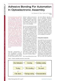
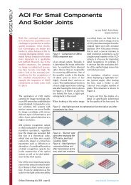
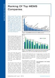
Figure 6 - Absorption of metals and insulatorsThe driving force behind this strongmarket forecast for FPCs is the miniaturisationand increased functionalityof mobile phones and digital cameras.System intelligence equal to that of asmall pocket PC, larger high-resolutiondisplays to view pictures takenwith an integrated high-resolutioncamera, and mobile TV are already integralfeatures of many of today’s mobilephones. FPC interconnects withthinner materials and finer lines andspaces will contribute to enable morecomponents to be integrated and thesize of the mobile phone to be reducedat the same time.The key to success with FPC manufacturingis in the control of productiontechniques. Techniques that arequite simple in theory, including theseparation (i. e. the cutting) of singlecircuits within a panel, may prove verydifficult in practice. Integrating newand innovative manufacturing techniquesand automation can contributeto an increase in quality and yieldas well as helping to keep pace withproduct requirements. Time-to-marketis also one of the most importantissues for FPC manufacturers. Beingable to react quickly to layout changesduring prototyping and pilot productionruns can be a further key to success.For this reason, laser technology,generally used as a tool for drilling thesmallest micro vias in advanced ICpackages, flexible circuits and highdensitycircuits (HDI boards), is nowadaysused more and more for cuttingFPCs. Expensive tooling and extensivetime-consuming manufacturingsteps, particularly in prototyping andpre-series production, can be eliminated,guaranteeing excellent qualityand yield at the same time.Conventional tool-based technologyvs. laser technologyThis comparison of laser cutting andconventional cutting techniques focuseson the following two processsteps within the prototyping and preseriesproduction of FPCs: coverlaycutting for prototyping and pre-series,and body cutting for prototyping, preseries,and low-volume series.Coverlay is one of the major differencesbetween flexible and rigid circuitboards. Coverlay is the mechanicalprotector for the fragile conductorson flex circuits and determines thesolder coating areas (apertures) forcomponent assembly. Usually, thesame films are used as base materialof coverlay and substrates. The majorproblem in manufacturing the coverlayfilms for FPCs is dimensional distortionduring the lamination process,which makes automation difficult andincreases costs. Apertures are usuallyintroduced into the coverlay films priorto lamination. Coverlay films usuallycomprise polyimide with a thicknessof either 12.5µm or 25µm coatedon one side with adhesive attached torelease paper.Figure 7 - 2D scannerwith galvanometermounted mirrorsFigure 5 - Punching dies for FPCs(Source: Dongguan Haoji Mould &Die Factory)Body cutting refers to the singulationof flexible circuits from their panel.Usually this comprises the cutting ofarbitrary shapes into a combinationof polyimide layers with adhesives(single or double side, double access,multi-layer). Connectors, Copper layersand stiffeners (e.g. FR4 or Polyimide)have to be cut out as well.Conventional tool-based technologiesto cut coverlay, flex and flex-rigid circuitscomprise punching and routing.Punching involves cutting dies witheither hard or soft tools. Hard tools areproduced from hardened steel and aremade to precise tolerances achievingup to 50µm accuracy in cutting. Softtools such as steel rule-dies (SRDs)are made of plywood, into whichare embedded semi-hardened steelblades: achievable accuracy is limitedto approximately 100µm. Routing, onthe other hand, is a dynamic, vectorbasedcutting method characterisedby a computer programme movingthe flex circuit relative to the cuttingtool. Because a router is software controlledon the basis of CAD data, waitingfor tooling is not necessary, flexibilityis high, and the achievable accuracyis relatively low, approximatelyFigure 8 - The LPKF MicroLine 350DPCBFABRICATIONF L E X & R I G I D - F L E Xwww.Onboard-Technology.com<strong>OnBoard</strong> Technology June 2006 - page 19
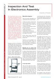
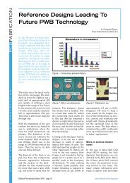
PCBFABRICATIONFigure 9 - Effective cutting speed ofpolyimide sheets as a function ofmaterial thickness100µm. All conventional technologiesare accompanied with significant burrformation.Laser cutting, being a vector-basedtechnology, offers the same advantagesas any other vector-based technology.Furthermore, as a non-contacttool, the laser completely eliminatesmechanical stress on the material.<strong>Burr</strong> formation and micro-crackingin solder resist are also avoided. Dueto the small beam diameter (approximately20µm), only a small volume ofmaterial is removed. The nature of thelaser ablation process, i.e. evaporationof material, significantly reduces depositson the circuits. The ability tocut complex shapes without stress andwith an extremely small tool diameterallows for more circuits on a singlepanel, increasing the net usable area.The achievable accuracy of laser cuttingrigid-flex boards is significantlybetter than that of any other conventionaltechnology.Laser cutting also offers economicadvantages. Tooling costs are inexistent.Hard and soft tools, on the otherhand, are expensive with prices rangingfrom $50 to $100 for soft tools andfrom $700 to $900 for hard tools. Dueto the complex nature of manufacturinghard tools, lead times are generallyfrom two to four weeks. Soft toolscan be made in a few days. Laser-basedproduction can start on the same daybased directly on the customer’s data,with no delays for tooling (cutting dieor routing adapter). The manufacturercan instantly react to layout changes.With market requirements regardingprecision, burr formation and leadtimes in prototyping and pre-seriesproduction getting tighter, conventionaltechnologies are no longer thebest choice.Laser cutting: process descriptionThe processing speed and the resultingquality depend on both thecharacteristics of the material beingprocessed and the nature of the laseremission (wavelength, fluence, peakpower, pulse width, and pulse rate). Itis important to know the absorptioncharacteristics of the material to becut. Most insulators, and thus polyimides,absorb radiation in the UVand far IR region (Figure 6). Q-Switchfrequency-tripled diode-pumped Nd:YAG lasers (UV-DPSS) emitting awavelength of 355nm are the correctchoice in the UV region, producingshort optical laser pulses in the rangeof a few tens of nanoseconds in length,with a peak power in the range of afew kilowatts.In the far IR region, the laser radiationof CO 2lasers with wavelengthsof, for example, 10.6 µm is stronglyabsorbed. However, IR lasers removematerial by intense local heating leavingcarbonisation and residue thatmust be cleaned during post-processing.Furthermore, far-IR radiation iscompletely reflected by Copper. As aresult CO 2lasers are not suitable forcutting flex or flex-rigid circuits.Material ablation in the UV region isbased on a different process. Incidentphotons are absorbed in a thin layer ofthe material up to the optical penetrationdepth. This is the depth at whichthe intensity of the absorbed radiationFigure 10 - Coverlay cutting: 12.5µm PI + 25µm adhesive (right and left); 25µm PI + 25µm adhesive (centre)F L E X & R I G I D - F L E XFigure 11 - Flex rigid cutting: transition area between flex and rigid part (left and right); rigid part of PCB (centre)<strong>OnBoard</strong> Technology June 2006 - page 20www.Onboard-Technology.com
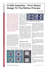
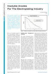
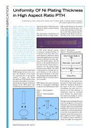
has decreased by a factor of 1/e. Theenergy released is transformed intoheat and transferred to the moleculechains. When the evaporation temperatureof the material is exceeded,the material explosively evaporatesand leaves the cutting kerf. The heatdiffuses from the surface layer intothe material. The thermal diffusiondepth is a function of the material’sdiffusion coefficient as well as the laser-beampulse length.In any case, an improved cuttingquality can be achieved by reducingthe thermal influence on the material,i. e. by keeping the heat-affectedzone and charring/carbonisation to aminimum. The optical and thermalpenetration depth parameters providea good estimate of how much thermalinfluence is involved in the cuttingprocess: the smaller the parametersand the smaller the thermal penetrationdepth compared to the opticalpenetration depth, the more the energyis confined to a small volume,increasing the thermal gradient andthus the cutting quality.Polyimide is used for flex circuits dueto its high thermal and chemical stability.It does not have a melting pointwhen cut with a laser but is directlyevaporated. Based on its relatively lowevaporation temperature of 750°C, arelatively low laser power is needed toachieve high cutting speeds. A smalloptical penetration depth (277nm for355nm wavelength radiation) reducesthe volume of material in which theenergy is absorbed. The wavelength’sthermal penetration depth is alsosmall (178nm) due to the short laserpulses used. The result is a well-definedmaterial removal area and excellentcutting quality with a minimumof carbonisation.Laser cutting toolsBeam guiding system used for cuttingare based on a scanner: two galvanometer-mountedmirrors are usedin a vector-scanning configuration todirect the focused laser beam acrossthe work surface in a cut pattern createdby CAD/CAM software. As such,being nearly inertia-free, extremelyhigh acceleration and high movingspeeds are possible.The MicroLine 350D laser systemfrom LPKF is especially designed tocut standard format coverlay films,flex and flex-rigid circuits. It comprisesa scanner providing precise,high speed beam movement as wellas a fast and dynamic x-y table (Tablesize 460mm x 310mm) that movesthe sheets and panels into the workingarea of the scanner. Accurate x-y-theta alignment of the laser focalspot is achieved through a CCD camera-basedvision registration system.Vision registration and high positionaccuracy of the x-y-table coupled witha focused spot size of approximately16µm enable this system to achievelevels of accuracy as high as +/- 20µm.Automatic calibration by means of aspecial sensor removes the effects ofthermally induced drift of the scannerand eliminates laser power variations.LPKF uses advanced dust and particleextraction and filtering to prevent anycontamination of the workpiece orthe environment. The CircuitMastersoftware supplied with MicroLine Serieslaser systems provides flexible andintuitive system control. The softwarecontrols all process parameters so newmaterials and processing techniquescan be accommodated. The system isalso available in a sealed housing thatcan be integrated into an existing productionline.<strong>Cutting</strong> results and examplesTo evaluate the performance of the lasersystem, a good benchmark is to cutstraight lines into polyimide sheets ofdifferent material thicknesses. Duringtesting at LPKF, the cutting qualitywas taken into account, with theobjective of maximising speed whileminimising carbonisation at thesame time. As such the numbers inFigure 9 do not represent the maximumachievable cutting speed, butrealistic figures with regard to whatis accepted by customers in termsof cutting quality. The cutting speedin flex and flex-rigid circuits will belower since such circuits comprisenumerous polyimide sheets bondedwith adhesives and even stiffeners(e.g. FR4) and Copper layers have tobe cut around connectors.As can be seen from Figure 9 themaximum effective cutting speedpossible for high-quality cuts in25µm material is approximately350mm/s. Even for thick materialsthe achievable cutting speed is highwith 42mm/s. Aside from optimisingparameters like pulse repetitionrate, average power, pulse overlapand so on, the cutting strategy applied(single-pass or multi-pass) is avital parameter for achieving a goodquality cut. The real challenge is tofind an optimum parameter set. TheMicroLine 350D’s control softwaresupports the user by supplying predefinedparameter sets, which arebased on the substantiated processknowledge of LPKF’s application engineers.Figures 10-12 show variousapplication examples with coveringcoverlay as well as flex and flex-rigidcircuits. All results show an excellentcutting precision, no burr and littleto no carbonisation.Figure 12 - Flex cutting: FPC connector (left); FPC with embedded Copper track (centre); single layer FPC (right)PCBFABRICATIONF L E X & R I G I D - F L E Xwww.Onboard-Technology.com<strong>OnBoard</strong> Technology June 2006 - page 21