Nanoimprint Lithography For High Volume HDI Manufacturing
Nanoimprint Lithography For High Volume HDI Manufacturing
Nanoimprint Lithography For High Volume HDI Manufacturing
- No tags were found...

Create successful ePaper yourself
Turn your PDF publications into a flip-book with our unique Google optimized e-Paper software.
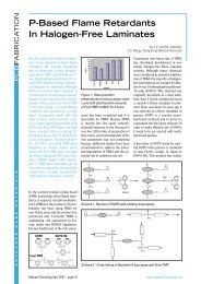
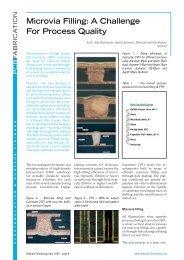
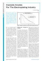
ASSEMBLY<strong>Nanoimprint</strong> <strong>Lithography</strong> <strong>For</strong> <strong>High</strong><strong>Volume</strong> <strong>HDI</strong> <strong>Manufacturing</strong>The growth of the electronics industryhas resulted in a greaterdemand for high density interconnect(<strong>HDI</strong>) structures. <strong>HDI</strong> structuresare used to meet the demandsfor lighter, more compact devicesthat offer superior performance.Examples of such <strong>HDI</strong>s are rigidor flexible micro-via PWBs, chipscalepackage substrates and ceramics-basedsubstrates. <strong>HDI</strong>s findapplications in ink jets, automotivedisplays, computer hard diskdrives, mobile phones, telecommunicationequipment, high-endIC packaging, flat panel displays,chip on suspension and medicaldevice applications. However, conventionalelectronics manufacturingtechnologies have processinglimitations, low manufacturingyields, high production costs andlimited flexibility for <strong>HDI</strong> applications.Such drawbacks have resultedin the need for alternativetechnologies capable of meetingmarket demands. <strong>Nanoimprint</strong> lithography(NIL) is a new technologywhich can improve cycle time,ensure yields and reduce productioncosts in the manufacture offlexible, rigid-flexible or <strong>HDI</strong> circuits,for example. The technologyallows for the manufacturing ofcomplex multi-layer circuits withtracks and vias with linewidthsdown to a few microns.by Marc Beck and Babak Heidari,ObducatSome years ago, nanoimprint lithography(NIL) was consideredto be one of the most promisingcandidates for large-scale productionof nanometer-sized structures.Since then several researchgroups and companies around theworld have spent a lot of time developingequipment and processesfor a large number of applications.Global players within the semiconductorand electronics industryFigure 1 - Process flow for creation of an <strong>HDI</strong> double layer comprisingconductive layer and viashave been and still are evaluatingNIL for their purposes. The resultsfrom these efforts prove that nanoimprintlithography is not onlyby far the fastest method availablefor nanoreplication, it also offersunbeatable resolution. Furthermore,it has also been shown thatthe technology offers fabricationadvantages for much larger structuresresiding in the micrometerrange, such as <strong>HDI</strong>. Today, theOnBoard Technology September 2006 - page 52www.Onboard-Technology.com
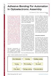
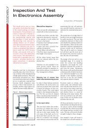
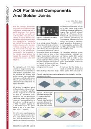
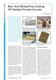
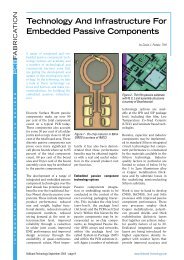
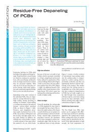
first companies have started producingcomponents using NIL.In the following, the focus is onthe imprint of <strong>HDI</strong> structuresemploying a three level imprinttemplate. We take a look at thebenefits arising from NIL for <strong>HDI</strong>applications and also present analternative concept for high volumemanufacturing using NIL.UV-lithography and nanoimprintlithography: a comparisonIn a traditional UV-lithographybasedprocess for interconnects,numerous steps are required togenerate one conductive layer andthe via holes. The process includessteps such as resist deposition,photolithography, development,deposition of metal layers and dielectriclayers, polishing, laminating,and so on.<strong>Nanoimprint</strong> lithography is apromising technology as it enablesmultiple layers to be printedin a single imprint step by employinga multilayered stamp. Bydoing so, the imprinted polymercan serve as the dielectric layer,reducing the number of processsteps significantly, down to 5-6steps per double layer dependingon the stamp material used. Thethree-dimensional structures obtainedafter imprint can finally befilled with conductive material,preferably Copper. The reductionof process steps will therefore resultin a significant reduction inprocess costs.The process can be performed usinga hard stamp material such asSilicon, Nickel, or quartz, as wellas Obducat’s proprietary IPS-STUprocess involving polymer stamps.Soft-press NIL technology is necessaryto achieve good results interms of a homogeneously distributedresidual layer thickness afterimprint. Both technology andprocess are currently combined ina high volume manufacturing tool(Figure 2).The IPS-STU conceptAs illustrated in Figure 1, theprocess sequence starts with step1 generating an intermediatepolymer stamp (IPS) from a hardmaster stamp (Si, Ni or quartz)by an imprint process. In a secondimprint (step 3 in Figure 1)the IPS is used as a single usetemplate in a simultaneous thermaland UV-process (STU). Thetwo imprint steps are performedin parallel at different locationsinside the HVM tool to increasethroughput. An illustration of theHVM tool configured for waferscale imprinting of wafers up to8” diameter is shown in Figure 2.Since Obducat’ssoft-presst e c h n o l o g yemploys compressed gas ratherthan rigid material, homogeneouspressure distribution acrossthe entire imprint area can beguaranteed along with the possibilityof increasing the imprintarea to any desired size or shapein customer specific tools. Softpress technology thereby enablesprinting to take place on largesubstrates i.e. PCBs or glass forflat panel displays.Further benefits of the IPS-STUconceptare reduced defect area,longer lifetime of the masterstamp material, lower cost ofownership and increased cleanlinessthrough self-cleaning of themaster. A comparison betweentraditional NIL employing hardstamps and the IPS-STU conceptemploying single-use polymerreplicas is illustrated in Figure 3.A three-level master stamp canbe produced easily by standardUV lithography and ICP etching.Subsequent coating with amonomolecular anti-adhesionlayer enables reproduction into alarge number of IPSs by imprinting.No polymer residues adhereto the master making intermediatecleaning procedures obsolete.The separation between masterand IPS is performed automatically.ASSEMBLYFigure 2 – A first generation IPS-STU HVM-tool withFOUPs for substrates up to 8 inches in diameter.The soft press technology is scalable and secondgeneration tools that can handle larger areasubstrates will followFigure 3 - Comparison between traditional hard stampNIL and the IPS techniquewww.Onboard-Technology.comOnBoard Technology September 2006 - page 53
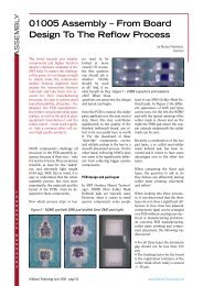
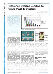
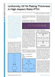
Figure 6 - Optical micrographobtained after aligning the stampwith its via pillars and connectorsto a PCB substrate with Copperpattern and printingcations. The number of processsteps reduces significantly as theimprint polymer can act as thedielectric layer itself. Soft-presstechnology with compressed airmeans that equipment can bescaled up towards the requirementsof the PCB industry,thereby allowing for the printingon substrates with sizes of,for example, 18” x 24”. Currentdevelopment work focuses on optimisationof the alignment accuracyfor the printing of entirePCB panels.Figure 7 - Optical micrographshowing a cross-section ofdouble side imprinted vias andtraces aligned to each side of thesubstrateASSEMBLYSiplace <strong>For</strong> Die-Attach And Flip-Chip ApplicationsThe Siplace A1 is a single-gantry machine featuringeutectic bonding in addition to die-attach and flipchipbonding. The system is capable of processingmore than 200 different die types and works with alltypes of feed systems such as wafers, waffle packs, gelpacks or tapes. Passive components can also be suppliedvia five 8mm tape feeders. Thanks to its flexibility,the Siplace A1 is ideally suited for multi-chipapplications, and with its large processing area it iscapable of handling very large substrates up to 640 x150 x 55 mm for epoxy applications and 30 x 35 mmfor eutectic applications. A gantry-mounted cameraensures the high placement accuracy of up to +/–10µm at 3 sigma and 1,500 dies per hour. The largenumber of stamping tools, bond tools and die ejectorconfigurations makes the new Siplace A-Serieseven more flexible and functional. Like the hardware,the software is also designed for the requirements ofmulti-chip applications. The enhanced software packagefor individual die processing, features a completerange of programming options. Users can define pickuppositions and program epoxy/die placement andalignment sequences in easy steps.Siemens Automation and Drives (A&D) has presentedits first die bonding system with the Siplace A-Series.According to Siemens, this new machine platform isideally suited for manufacturing plants where die-attachas well as flip-chip applications must be executedwith speed, flexibility and reliability. Two machineversions are available: the Siplace A1 with one gantryand the Siplace A2 with two gantries.The dual-gantry Siplace A2 operates with two parallelgantries. While one dispenser-equipped gantry appliesthe adhesive or stamps the epoxy, the second gantryplaces dies. Thanks to the simultaneous dispensingand bonding operations, the Siplace A2 achieves aplacement performance of 3,600 dies per hour withan accuracy of +/– 12µm at 3 sigma. The substrateprocessing is equally flexible, because the Siplace A2can handle boat and carrier substrates as well as stripand lead-frame substrates with sizes of up to 200 x150 x 40 mm and die sizes ranging from 0.125 mm 2to 25 mm 2 .SiemensAutomation and DrivesElectronics Assembly SystemsRupert-Mayer-Straße 4481350 Munich - GermanyTel. +49 89 20800 26439; Fax +49 89 20800 45727susanne.oswald@siemens.comwww.siplace.comwww.Onboard-Technology.comOnBoard Technology September 2006 - page 55