Thermo Scientific Orion 2110XP Ammonia Analyzer
Thermo Scientific Orion 2110XP Ammonia Analyzer
Thermo Scientific Orion 2110XP Ammonia Analyzer

You also want an ePaper? Increase the reach of your titles
YUMPU automatically turns print PDFs into web optimized ePapers that Google loves.
<strong>Thermo</strong> <strong>Scientific</strong><strong>Orion</strong> <strong>2110XP</strong><strong>Ammonia</strong> <strong>Analyzer</strong>User Guide
ROSS and the COIL trade dress are trademarks of <strong>Thermo</strong> Fisher <strong>Scientific</strong> Inc. U.S. patent 6,793,787.AQUAfast, Cahn, ionplus, KNIpHE, No Cal, ORION, perpHect, PerpHecT, PerpHecTion, pHISA, pHuture, Pure Water, Sage, Sensing the Future, SensorLink,ROSS, ROSS Ultra, Sure-Flow, Titrator PLUS and TURBO2 are registered trademarks of <strong>Thermo</strong> Fisher.1-888-pHAX-ION, A+, All in One, Aplus, AQUAsnap, AssuredAccuracy, AUTO-BAR, AUTO-CAL, AUTO DISPENSER, Auto-ID, AUTO-LOG, AUTO-READ,AUTO-STIR, Auto-Test, BOD AutoEZ, Cable-Free, CERTI-CAL, CISA, DataCOLLECT, DataPLUS, digital LogR, DirectCal, DuraProbe, Environmental ProductAuthority, Extra Easy/Extra Value, FAST QC, GAP, GLPcal, GLPcheck, GLPdoc, ISEasy, KAP, LabConnect, LogR, Low Maintenance Triode, Minimum StirRequirement, MSR, NISS, One-Touch, One-Touch Calibration, One-Touch Measurement, Optimum Results, <strong>Orion</strong> Star, Pentrode, pHuture MMS, pHuturePentrode, pHuture Quatrode, pHuture Triode, Quatrode, QuiKcheK, rf link, ROSS Resolution, SAOB, SMART AVERAGING, Smart CheK, SMART STABILITY,Stacked, Star Navigator 21, Stat Face, The Enhanced Lab, ThermaSense, Triode, TRIUMpH, Unbreakable pH, Universal Access are trademarks of<strong>Thermo</strong> Fisher.Guaranteed Success and The Technical Edge are service marks of <strong>Thermo</strong> Fisher.PerpHecT meters are protected by U.S. patent 6,168,707.PerpHecT ROSS electrodes are protected by U.S. patent 6,168,707.ORION Series A meters and 900A printer are protected by U.S. patents 5,198,093, D334,208 and D346,753.ionplus electrodes and Optimum Results solutions are protected by U.S. patent 5,830,338.ROSS Ultra electrodes are protected by U.S. patent 6,793,787.ORP standard is protected by U.S. patent 6,350,367.No Cal electrodes are protected by U.S. patent 7,276,142.© 2009 <strong>Thermo</strong> Fisher <strong>Scientific</strong> Inc. All rights reserved. All trademarks are the property of <strong>Thermo</strong> Fisher <strong>Scientific</strong> Inc. and its subsidiaries.The specifications, descriptions, drawings, ordering information and part numbers within this document are subject to change without notice.This publication supersedes all previous publications on this subject.
Table of ContentsChapter IGeneral Information. . . . . . . . . . . . . . . . . . . . . . . . . . . . . . . . . . . . . . . . . . . . I-1Introduction.. . . . . . . . . . . . . . . . . . . . . . . . . . . . . . . . . . . . . . . . . . . . . I-1Features and Benefits. . . . . . . . . . . . . . . . . . . . . . . . . . . . . . . . . . . . . . . I-2Principles of Operation . . . . . . . . . . . . . . . . . . . . . . . . . . . . . . . . . . . . . I-3Principles of Calibration.. . . . . . . . . . . . . . . . . . . . . . . . . . . . . . . . . . . . I-5Double Known Addition (DKA).. . . . . . . . . . . . . . . . . . . . . . . . . . . . I-5Offline Calibration. . . . . . . . . . . . . . . . . . . . . . . . . . . . . . . . . . . . . . . I-6Fluidics Diagram. . . . . . . . . . . . . . . . . . . . . . . . . . . . . . . . . . . . . . . . . . I-7Glossary. . . . . . . . . . . . . . . . . . . . . . . . . . . . . . . . . . . . . . . . . . . . . . . . . I-8Two Channel <strong>Analyzer</strong> Configurations.. . . . . . . . . . . . . . . . . . . . . . . . I-10Chapter II<strong>Analyzer</strong> Preparation. . . . . . . . . . . . . . . . . . . . . . . . . . . . . . . . . . . . . . . . . . II-1Unpacking the <strong>Analyzer</strong>. . . . . . . . . . . . . . . . . . . . . . . . . . . . . . . . . . . . II-1Mounting and Plumbing Instructions . . . . . . . . . . . . . . . . . . . . . . . . . II-2Sample Requirements.. . . . . . . . . . . . . . . . . . . . . . . . . . . . . . . . . . . . . II-3Electrical Wiring . . . . . . . . . . . . . . . . . . . . . . . . . . . . . . . . . . . . . . . . . II-4Safety Requirements .. . . . . . . . . . . . . . . . . . . . . . . . . . . . . . . . . . . . II-4Warning Labels and Locations.. . . . . . . . . . . . . . . . . . . . . . . . . . . . . II-5Wiring the <strong>Analyzer</strong>. . . . . . . . . . . . . . . . . . . . . . . . . . . . . . . . . . . . . . . II-6Terminal Assignments . . . . . . . . . . . . . . . . . . . . . . . . . . . . . . . . . . . . . II-8Electrode Wiring Assignments.. . . . . . . . . . . . . . . . . . . . . . . . . . . . . II-9Installation of Reagent and Diffusion Tubing. . . . . . . . . . . . . . . . . . . II-10Installation of New Electrode Cables. . . . . . . . . . . . . . . . . . . . . . . . . II-11Installation of a New <strong>Ammonia</strong> Electrode . . . . . . . . . . . . . . . . . . . . . II-12Installation of the ATC Probe.. . . . . . . . . . . . . . . . . . . . . . . . . . . . . . II-12Installation of a New Reference Electrode.. . . . . . . . . . . . . . . . . . . . . II-13Chapter III<strong>Analyzer</strong> Operation. . . . . . . . . . . . . . . . . . . . . . . . . . . . . . . . . . . . . . . . . . . . III-1Description of Basic Controls.. . . . . . . . . . . . . . . . . . . . . . . . . . . . . . III-1Description of Keypad Icons . . . . . . . . . . . . . . . . . . . . . . . . . . . . . . . III-2Use of the Setup Mode . . . . . . . . . . . . . . . . . . . . . . . . . . . . . . . . . . . III-3Setup Mode Overview. . . . . . . . . . . . . . . . . . . . . . . . . . . . . . . . . . . . III-5Shutdown and Start-Up Procedure.. . . . . . . . . . . . . . . . . . . . . . . . . III-35<strong>Thermo</strong> <strong>Scientific</strong> <strong>Orion</strong> <strong>2110XP</strong> <strong>Ammonia</strong> <strong>Analyzer</strong> User Guide
Chapter I General InformationThis user guide covers the operation, maintenance and troubleshootingfor the <strong>Thermo</strong> <strong>Scientific</strong> <strong>Orion</strong> <strong>2110XP</strong> ammonia analyzer, which offersunmatched reliability in analyzing ammonia in boiler feedwater.IntroductionUnlike pH and conductivity measurements, which are affected by otherchemicals that are present in the sample, direct ammonia measurementwith the <strong>2110XP</strong> ammonia analyzer provides accurate measurements witheven the slightest change in ammonia concentration for the best control ofchemical feeds. The system optimizes the fluidic design with our sensingtechnology to provide precise results, simplifying your process with easeand without excessive operating costs.The <strong>2110XP</strong> ammonia analyzer meets all of the criteria for accurateand dependable ammonia monitoring and more. The <strong>2110XP</strong> analyzerincorporates innovative technologies that include:• Premium electrodes• Accurate and precise flow cell design• Marquee help screen• Pump-less reagent addition and DKA calibration system<strong>Thermo</strong> <strong>Scientific</strong> <strong>Orion</strong> <strong>2110XP</strong> <strong>Ammonia</strong> <strong>Analyzer</strong>Markets• Power• Pulp and paper• Agricultural• SemiconductorApplications• RO feedwater monitoring• Seawater-cooled condenser leak detection• Boiler water monitoring• Agricultural water monitoring<strong>Thermo</strong> <strong>Scientific</strong> <strong>Orion</strong> <strong>2110XP</strong> <strong>Ammonia</strong> <strong>Analyzer</strong> User GuideI-1
General InformationFeatures and BenefitsThe <strong>Thermo</strong> <strong>Scientific</strong> <strong>Orion</strong> <strong>2110XP</strong> ammonia analyzer is ideal formeasuring and monitoring the critical ammonia levels in industrial wateror agricultural water applications. With limited maintenance requirementsand low reagent usage, the <strong>2110XP</strong> analyzer can also be used in remotemonitoring applications.• Measurement of ammonia in water using premium <strong>Thermo</strong> <strong>Scientific</strong><strong>Orion</strong> ion selective electrode (ISE) technology.• Accurate and precise measurements in the range of 0 to 10 ppm:• Reliable measurements and a wide measurement range withselectable resolution.• Measures ammonia ion activity in aqueous solutions quickly,accurately and economically.• Premium reference and sensing electrodes:• Superior accuracy and stability over a wide temperature range.• Advanced flow cell design with air stirring:• Automatic sample handling and contamination control with nomoving parts.• Patented scrolling marquee:• Intuitive menu-driven digital user interface.• Data log of previous measurements and calibration:• View measurement, calibration and error history.• Self diagnostics:• Ease of maintainability.• Password protection:• Security and peace of mind for your operation.• Auto-ranging electronics with an easy to read backlit LCD display:• <strong>Analyzer</strong> determines the best range.<strong>Thermo</strong> <strong>Scientific</strong> <strong>Orion</strong> <strong>2110XP</strong> <strong>Ammonia</strong> <strong>Analyzer</strong> User GuideI-2
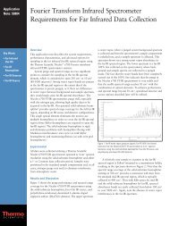
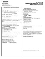
General InformationPrinciples of OperationThe sample enters the <strong>Thermo</strong> <strong>Scientific</strong> <strong>Orion</strong> <strong>2110XP</strong> ammonia analyzerand passes through the inlet valve, bypass/needle valve, inlet filter, pressureregulator, flow meter and into the restrictor tubing. The sample then passesthrough the flow cell manifold into a reagent bottle through a diffusiontubing assembly where pH adjustment takes place. The pH-adjusted samplethen flows back through the manifold into the flow cell as air is introducedfrom the air pump to ensure proper mixing and fast response. The samplethen flows into an atmospheric drain via the diverter valve.K E YFigure I-1<strong>2110XP</strong> Schematic<strong>Analyzer</strong>Reference SolutionAir PumpElectricFluid PathFluid Restrictor TubingAir PathReference Solution PathReagent Overflow PathDiffusion Tubing1 2 3 4 5Power4-20mA OutputRestrictor TubingAir FilterCheckValveAir InletFlow MeterPressurizes Flow Cellto Initiate SiphoningSenseTEMPREFCalibrationPortSafety Drain forReagent OverflowCalibration LevelRegulatorValveMeasure LevelBypass / NeedleValve and FilterCalInlet ValveSampleValveFlow Cell BlockReagent ManifoldValve PositionsCalibration Mode - PUSHSample/Measure Mode - PULLDiffusion TubeReagentReagent BottleMain FeedDrain<strong>Thermo</strong> <strong>Scientific</strong> <strong>Orion</strong> <strong>2110XP</strong> <strong>Ammonia</strong> <strong>Analyzer</strong> User GuideI-3
General InformationThe sensing electrode responds logarithmically to changes in the ammoniaion concentration. This response is described by the Nernst equation:Where:E = E o + 2.3 (RT/nF) log (C/C iso )E = measured electrode potential, mVE o = potential, when C equals C iso , mVR = ideal gas constantT = temperature of sample, degrees KnF= valence of ionic species (+1 for ammonia ion)= Faraday’s constantC = effective ammonia ion concentration (activity)C iso = concentration (activity) of ammonia ion where potential E istemperature independent (isopotential point)The above equation indicates that the measured potential varies with bothtemperature and the concentration of the ion of the interest. In order toeliminate error caused by fluctuations in sample temperature, the <strong>2110XP</strong>microprocessor constantly updates temperature corrections from datasupplied by the ATC probe.From the Nernst equation, the theoretical response of a ammonia ionselective electrode to a ten-fold change in concentration at 25 °C is59.16 mV. This is referred to as the electrode slope (S). Most electrodes,however, do not exhibit a theoretical slope. Therefore, the analyzer iscalibrated to determine its actual value. Two standards are used to provideinformation necessary for the microprocessor to compute the actual slopeand E 0 for use during sample analysis.In order to eliminate interference from hydrogen ions, which can becomesignificant when measuring low levels of ammonia, the <strong>2110XP</strong> analyzeradjusts the sample pH. This pH adjustment is accomplished by thepatented passive-diffusion process wherein the sample passes througha length of tubing contained in the reagent bottle. The reagent diffusesthrough the tube wall and mixes with the sample, which adjusts the samplepH to below 4.<strong>Thermo</strong> <strong>Scientific</strong> <strong>Orion</strong> <strong>2110XP</strong> <strong>Ammonia</strong> <strong>Analyzer</strong> User GuideI-4
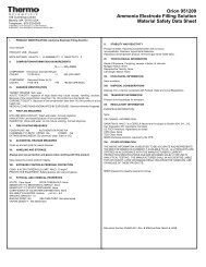
General InformationPrinciples ofCalibrationDouble KnownAddition (DKA)Calibration procedures for analytical instruments are important and mustbe performed carefully. The calibration procedure used in the <strong>Thermo</strong><strong>Scientific</strong> <strong>Orion</strong> <strong>2110XP</strong> is a variation of Double Known Addition (DKA)using advanced electrode and flow cell technology in combination with thepassive diffusion system. This method has the distinct advantages of beingfast, easy, and accurate.Before calibration begins, the diverter valve is pushed in to divert flow fromthe measure drain, allowing the flow cell to fill.At the beginning of the DKA calibration the actual concentration in thesample is unknown. The analyzer measures the potential (E s ) and storesthis value in the microprocessor. A known amount of standard 1 solutionis added to the flow cell, which increases the concentration (C s ) with acorresponding known amount (dC 1 ). During this process, air is pumpedinto the flow cell, thoroughly mixing sample and standard in a closedloopsystem. The new potential (E 1 ) is measured and stored automaticallywhen stability is reached. Adding standard 2, preferably 10 times moreconcentrated than standard 1, increases the concentration (dC 2 ) in thesample reservoir. Again, the new potential (E 2 ) is measured and storedwhen the reading is stable. Now, we have the following three unknowns:E s =E o + S(T s /298.15) log (C s /C iso )E 1 =E o + S(T 1 /298.15) log [(C s + dC 1 )/C iso ]E 2 =E o + S(T 2 /298.15) log [(C s + dC 1 + dC 2 )/C iso ]S is the Slope at 25 °C (298.15 K)T is the temperature in Kelvin, measured when the potential E is measured.Figure I-2Flow Cell Volume for DKAE s , E 1 , E 2 have been determined during the calibration procedure. Themicroprocessor solves these three equations, to obtain the values of Sand E o . The calibration result is stored for use during online monitoringto convert the measured potential and temperature in the sample intoconcentration values in either ppm or ppb.When the calibration is complete the flow cell drains as the sample flowreturns. The flow cell volume returns to the measurement level. Afterallowing approximately 30 minutes for concentrated calibration solutionto be flushed from the system, the <strong>2110XP</strong> analyzer can begin samplemeasurement again.In addition to Double Known Addition (DKA), the <strong>2110XP</strong> analyzer alsoallows the operator the ability to perform an offline calibration.<strong>Thermo</strong> <strong>Scientific</strong> <strong>Orion</strong> <strong>2110XP</strong> <strong>Ammonia</strong> <strong>Analyzer</strong> User GuideI-5
General InformationOffline CalibrationThe offline calibration feature of the <strong>2110XP</strong> analyzer allows the operatorto adjust the analyzer to values determined by alternate methods used intheir laboratory such as elemental spectroscopy and ion chromatography.The offline calibration is essentially a one point calibration. To perform anoffline calibration, a sample is taken from the bypass of the analyzer; thesample concentration value is stored in memory; the sample is analyzedby an alternate method of choice; the previously stored reading is adjustedto the lab method result; and the analyzer is then returned to the analysismode. The term “offline calibration” refers only to the fact that a samplefrom <strong>2110XP</strong> analyzer bypass is taken “offline” for laboratory analysis; infact, no downtime is experienced during the procedure and the analyzerremains online throughout.<strong>Thermo</strong> <strong>Scientific</strong> <strong>Orion</strong> <strong>2110XP</strong> <strong>Ammonia</strong> <strong>Analyzer</strong> User GuideI-6
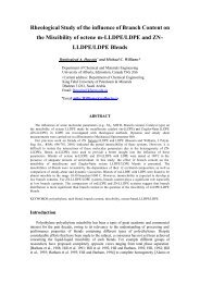
General InformationFluidics DiagramMode IndicatorScrolling MarqueeLCD DisplayWarning IconStatus IndicatorsKeypadMountingHoleReferenceFillingSolutionAir PumpORION <strong>2110XP</strong><strong>Ammonia</strong>Flow MeterRestructorTubeAssemblyCalibration PortFlow CellReservoirSiphon TubeFlow Cell BlockDiverter ValveCheck ValvePressureRegulatorReagentManifoldBypass/NeedleValveInlet FilterDiffusion TubingAssemblyReagentBottleAdapterAssemblyReagent BottleInlet ValveFigure I-3Fluidics Diagram<strong>Thermo</strong> <strong>Scientific</strong> <strong>Orion</strong> <strong>2110XP</strong> <strong>Ammonia</strong> <strong>Analyzer</strong> User GuideI-7
General InformationGlossaryRefer to Figure I-3.Inlet Valve – Accepts the sample stream via 1/4 inch NPTF connector. Theoperator must supply the sample with a pressure between 14 and 100 psig.Inlet Filter – 60 micron stainless steel filter traps particulate matter insample stream.Bypass/Needle Valve – Used to redirect flow in the bypass system.Pressure Regulator – Adjusts flow on the incoming sample stream.Flow Meter – Measures the sample flow rate.Check Valve – Prevents the backflow of sample.Restrictor Tube Assembly – Used in conjunction with the pressureregulator to lower downstream pressure.Reagent Manifold – Directs sample flow in and out of the reagentbottle assembly.Reagent Bottle Adapter Assembly – Connects the reagent bottle assemblyto the manifold.Diffusion Tubing Assembly – Semi-permeable tubing through which thereagent diffuses into the sample.Reagent Bottle – Contains the reagent that lowers the sample pH tobelow 4.Flow Cell – Contains the ammonia sensing electrode, reference electrodeand ATC probe.Diverter Valve – Allows the flow cell reservoir to fill during calibration byforming a closed-loop system.<strong>Ammonia</strong> Electrode – Senses ammonia ions in the sample stream andproduces an electrical potential dependent on the sample concentration.Reference Electrode – Provides a constant reference potential andcompletes the measurement circuit.Reference Electrode Filling Solution Bottle – Provides constant flow ofelectrolyte solution through reference electrode for maximum stability.<strong>Thermo</strong> <strong>Scientific</strong> <strong>Orion</strong> <strong>2110XP</strong> <strong>Ammonia</strong> <strong>Analyzer</strong> User GuideI-8
General InformationATC Probe – Measures the sample temperature and inputs the data to themicroprocessor for automatic temperature compensation (ATC).Calibration Port – Allows introduction of standards to the sample reservoirduring calibration.Air Pump – Used to mix the sample during both measurementand calibration.LCD Display – Provides digital readouts of concentration, temperature,millivolts and error codes.Keypad – Consists of five mode keys, four prompt indicator lights, twoscroll keys and one key for entering data. Mode and error indicators are alsoincorporated on the keypad.Status Indicator – Two LED lights that illuminate according to currentstatus of the analyzer.Green Light:Yellow Light:Red Light:Indicates that system is in correct working condition.Indicates a warning, system in hold or thatmaintenance is required.Indicates that something is seriously wrong.Note: When either the yellow or red LED is lit, there may be an entry inthe diagnostics mode that indicates the error. The logging feature must beinitiated in the setup mode. Refer to Chapter III, Use of the Setup Modefor instructions.<strong>Thermo</strong> <strong>Scientific</strong> <strong>Orion</strong> <strong>2110XP</strong> <strong>Ammonia</strong> <strong>Analyzer</strong> User GuideI-9
General InformationTwo Channel <strong>Analyzer</strong>ConfigurationsA pH/ORP module or conductivity module can be added by the operatorto the second channel of the <strong>Thermo</strong> <strong>Scientific</strong> <strong>Orion</strong> <strong>2110XP</strong> ammoniaanalyzer for the ultimate flexibility in measurement capabilities. The2100 series pH/ORP and conductivity analyzers provide accurate andreliable measurements in ultra pure water as well as the harshest industrialenvironments. Combined with decades of superior <strong>Thermo</strong> <strong>Scientific</strong><strong>Orion</strong> sensor technology, our systems provide rapid results withcomplete stability.Cat. No.2100PH22100CD2DescriptionSecond channel module for pH/ORPSecond channel module for conductivityWhen a pH/ORP module or conductivity module is installed on thesecond channel of the <strong>2110XP</strong> ammonia analyzer, refer to the <strong>Thermo</strong><strong>Scientific</strong> <strong>Orion</strong> 2100 Series pH/ORP <strong>Analyzer</strong> and Conductivity <strong>Analyzer</strong>User Guide for detailed instructions on operating the pH/ORP orconductivity analyzer. Visit www.thermo.com/processwater to downloadany of the 2100 series analyzer user guides.<strong>Thermo</strong> <strong>Scientific</strong> <strong>Orion</strong> <strong>2110XP</strong> <strong>Ammonia</strong> <strong>Analyzer</strong> User GuideI-10
Chapter II <strong>Analyzer</strong> PreparationUnpacking the<strong>Analyzer</strong><strong>Thermo</strong> <strong>Scientific</strong> <strong>Orion</strong> analyzers are assembled, tested and packaged withgreat care. Refer to Figure II-1.Report any obvious damage of shipping container to carrier and hold forinspection. The carrier (not <strong>Thermo</strong> Fisher <strong>Scientific</strong>) is responsible for anydamage incurred during shipment.1. Open the outer box. Remove the top two foam corner support pieces.2. Open the inner box. This box should contain the analyzer and ATCtemperature probe, ammonia electrode box, reference electrode box,ammonia standard solutions kit (two 2 oz bottles of 191 ppm ammoniastandard and two x 2 oz bottles of 1920 ppm ammonia standard), theoptions kit and user guide CD.3. Remove the cardboard retaining shell by sliding it over the entiremounting board and the analyzer.4. Carefully remove the entire mounting board with analyzer from theinner box.Note: Do not lift or pull the analyzer by the fluidics or theelectronic components.5. Unbolt the analyzer from the mounting board by removing the fourmounting bolts with a 9/16 wrench. These bolts may be discarded.6. Carefully place the analyzer at a convenient location until properinstallation can be completed.Figure II-1Unpacking the <strong>Analyzer</strong><strong>Thermo</strong> <strong>Scientific</strong> <strong>Orion</strong> <strong>2110XP</strong> <strong>Ammonia</strong> <strong>Analyzer</strong> User GuideII-1
<strong>Analyzer</strong> PreparationMounting andPlumbing InstructionsRefer to the Appendix, Mounting Dimensions section.Warning: Do not connect power prior to the mounting and plumbing ofthe analyzer.Recommendations• Select a site for the analyzer that allows it to be permanently boltedwith ample height for atmospheric drain operation. Be sure that there isready access to the electronic controls, calibration port and electrodes.• A clearance of 15 inches (about 40 cm) must be allowed above theflow cell calibration port. Insert the pipet vertically (not angled) duringthe calibration.• The analyzer location must permit connections to a sample line, drainand AC power supply and any connections for output devices.• The analyzer should be mounted as close to the sampling point aspossible. This ensures the fastest possible response to a changing samplecondition. Refer to the Appendix, Sample Conditions section.• For proper flow cell operation, the analyzer must be installed straightand level upon its mounting location. Failure to level the analyzer maycause poor siphoning in the flow cell.Instructions1. Prepare the mounting holes. Carefully lift the analyzer and bolt it intoplace. Do not lift the analyzer by holding on to any of the plumbing orfluid handling components.2. Connect a waste line to the outlet of the analyzer, which is 3⁄4 NPTmale. The waste line should be connected to a drain of sufficientcapacity, 0.5 inch (1.27 cm) OD is recommended.3. Connect a sample line to the inlet of the analyzer, which is 1⁄4 NPTfemale. It is recommended that a shutoff valve be installed at thesampling point.4. The analyzer must be mounted and leveled vertically for properoperation.<strong>Thermo</strong> <strong>Scientific</strong> <strong>Orion</strong> <strong>2110XP</strong> <strong>Ammonia</strong> <strong>Analyzer</strong> User GuideII-2
<strong>Analyzer</strong> PreparationSample RequirementsAdditional information is listed in the Appendix, Specifications section.Sample inlet connection – 1/4” NPTF. If particulate matter is present inthe sample, pre-filtration is necessary. The 60 micron stainless steel filterlocated after inlet valve will remove moderate amounts of particulates.Flow rate – 40 mL/minute (nominal).Pressure – 8 to 100 psig. Consult Technical Support for details on samplehandling if the pressure is outside of this range.Temperature – Temperature must be between 5 and 35 °C.<strong>Ammonia</strong> level – <strong>Ammonia</strong> levels are read directly in ppb or ppm, whencalibrated with <strong>Thermo</strong> <strong>Scientific</strong> <strong>Orion</strong> ammonia standards 1 and 2.Sample alkalinity – Sample alkalinity should be less than 250 ppm CaCO 3equivalent. For higher sample alkalinity, contact Technical Support.Sulfite – Sulfite cannot be present in the sample.<strong>Thermo</strong> <strong>Scientific</strong> <strong>Orion</strong> <strong>2110XP</strong> <strong>Ammonia</strong> <strong>Analyzer</strong> User GuideII-3
<strong>Analyzer</strong> PreparationElectrical WiringThe warning icon highlights important information that should be strictlyfollowed when using the analyzer for your own safety. Failure to followthese instructions may result in injuries.Warning: Read and observe the following safety recommendations.Safety Requirements• Prior to wiring, a switch or circuit breaker for disconnecting theanalyzer from power supply should be installed.• The switch should be in close proximity to the analyzer and witheasy reach of the user.• The switch should be marked as the disconnecting device forthe analyzer.• To reduce the risk of shock hazard, disconnect the power prior toopening the analyzer.• Before connecting the analyzer to the main, make sure that the voltagelies within either range: 85 to 132 V, 200 mA or 170 to 264 V,100 mA; 50 to 60 Hz AC.• Cutting off the power by disconnecting power source will not reset theanalyzer. This analyzer incorporates a non-volatile memory and willmaintain calibration and settings after power failure. Battery power issupplied to the display for the date and time functions.• If a repair is required, or to arrange Return Material Authorization, callTechnical Support or contact your local authorized dealer.• Installation and wiring of the analyzer may only be carried out inaccordance with applicable local and national codes per this user guide.• Be sure to observe the technical specifications and input ratings.<strong>Thermo</strong> <strong>Scientific</strong> <strong>Orion</strong> <strong>2110XP</strong> <strong>Ammonia</strong> <strong>Analyzer</strong> User GuideII-4
<strong>Analyzer</strong> PreparationWarning Labelsand LocationsWarning: The following section provides important information thatshould be strictly followed when using the analyzer for your own safety.Failure to follow these instructions may result in injuries.The safety warning icons are used in two locations on the analyzer.• Faceplate – Refer to Figure II-2.Figure II-2Faceplatet Ch 1t Ch 2Ch 1 statusCh 2 status• Power supply – Refer to Figure II-3.Figure II-3Power SupplyInput Power170 - 264V 100mA85 - 132V 200mAFuseNEUTRALGroundPower Supply115V230VFuse Type250V, 200mA Fast Acting250V, 100mA Fast ActingFuse HolderFuseNote: Replace the fuse only with a fuse of same rating.<strong>Thermo</strong> <strong>Scientific</strong> <strong>Orion</strong> <strong>2110XP</strong> <strong>Ammonia</strong> <strong>Analyzer</strong> User GuideII-5
<strong>Analyzer</strong> PreparationWiring the <strong>Analyzer</strong>Warning: Read and observe the following requirements. If you install thewrong fuse for your system, you could damage the analyzer. Make sure thatyou select the correct fuse rating and discard the additional fuses suppliedin the fuse kit.Required Tools• Options kit – includes fuses, cable glands, conduit fitting and greenscrew terminal.• Phillips head screwdriver.• 2 mm blade flat-head screwdriver.Figure II-4Electronics Enclosurewith Cable GlandsPower CableHole LocationsHinge Pin4 CaptiveScrewsCable GlandsElectrode Cables1. Open the faceplate – loosen the four screws using a Phillips headscrewdriver. The electronics faceplate will open via the hinge pinconnection.2. Remove one or two of the two unused cable glands as required forwiring power cable or auxiliary connections. Power cable optional holelocations are shown in Figure II-4.3. Select and install the appropriate size cable gland or conduit fittingas required.4. Feed the power cable through the conduit or cable glands as required.<strong>Thermo</strong> <strong>Scientific</strong> <strong>Orion</strong> <strong>2110XP</strong> <strong>Ammonia</strong> <strong>Analyzer</strong> User GuideII-6
<strong>Analyzer</strong> PreparationFigure II-5Terminal Connector LocationTerminal Connector5. Wire the power cable to the green screw terminal connector from theoptions kit. Select correct terminal for hot conductor depending on linevoltage. Refer to Figure II-5 for terminal connector location.6. Plug the terminal connector into the power supply. Refer toFigure II-3.7. Select the correct fuse from the fuse kit. Install by inserting the fuse inthe fuse holder and secure it using the twist and lock method. The fusesare clearly labeled with the appropriate voltages for your system. Referto Figure II-3. Refer to the table below for fuse selection.AC Voltage115V230VFuse Rating200mA, 250V, Fast Acting100mA, 250V Fast Acting<strong>Thermo</strong> <strong>Scientific</strong> <strong>Orion</strong> <strong>2110XP</strong> <strong>Ammonia</strong> <strong>Analyzer</strong> User GuideII-7
<strong>Analyzer</strong> PreparationTerminalAssignmentsTerminal Layout Terminal Layout Terminal Layout Terminal Layout1 Sout (mA)sensing signal2 GNDcommon ground3 Tout (mA)temp. signal4 Air pump(ISE only)5 Air pump(ISE only)6 Shield groundfor conductivity9 Relay 1 26 Sensingelectrode10 Relay 1 27 Do notconnect28 Do not connect29 Do not connect11 Relay 2 30 Preamp power12 Relay 2 31 Preamp ground13 Relay 3 32 Shield14 Relay 3 33 Shield7 Do not connect 15 Do not connect 34 Jumper to pin 26when using preamp8 Do not connect 16 Temperature ground17 Temperature drive18 Temperature sense19 Solution ground20 Conductivity drive +21 Conductivity sense +22 Conductivity sense -23 Conductivity drive -24 Reference electrode25 Jumper to pin 24when using preampFigure II-6Terminal Assignments9 10 11 12 13 14 15 16 17 18 19 20 21 22 23 24 2526271 2 3 4 5 6 7 828 29 30 31 32 33 34<strong>Thermo</strong> <strong>Scientific</strong> <strong>Orion</strong> <strong>2110XP</strong> <strong>Ammonia</strong> <strong>Analyzer</strong> User GuideII-8
<strong>Analyzer</strong> PreparationElectrode WiringAssignments<strong>Ammonia</strong> Electrode26 Sensing electrode Connect clear wire33 Shield Connect black wireReference Electrode24 Reference electrode Connect clear wire32 Shield Connect black wire2100TP Temperature Probe16 Temperature ground /thermistor Connect white wire17 Temperature drive /thermistor Connect green wire19 Solution ground Connect red wire2001TM Temperature Probe16 Temperature ground /thermistor Connect white wire17 Temperature drive /thermistor Connect green wire, jumper 17 and 1818 Temperature sense Jumper to 1719 Solution ground Connect red wire2001SC pH Electrode24 Reference electrode Connect black wire26 Sensing electrode Connect clear wire110250 ORP Electrode19 Solution ground Connect black wire24 Reference electrode Connect purple wire26 Sensing electrode Connect coax center wire2002CC and 2002SS Conductivity Probes6 Shield ground for conductivity Connect clear wire16 Temperature ground /thermistor Connect white wire17 Temperature drive /thermistor Connect black wire20 Conductivity drive + Connect orange wire21 Conductivity sense + Connect red wire22 Conductivity sense - Connect green wire23 Conductivity drive - Connect blue wireNote: Only reference the wiring configurations that are applicable to youranalyzer and electrodes.<strong>Thermo</strong> <strong>Scientific</strong> <strong>Orion</strong> <strong>2110XP</strong> <strong>Ammonia</strong> <strong>Analyzer</strong> User GuideII-9
<strong>Analyzer</strong> PreparationInstallation of Reagentand Diffusion TubingWarning: The reagent is hazardous. Use protective glasses and gloves. Referto the bottle label for precautions and work in a well-ventilated area.Note: Turn off the air pump before beginning this procedure; otherwise,the air pump will splatter the reagent outward as the bottle is removed.1. Remove the thumbnut and slide the bottle adaptor from the flow cell.2. Unscrew the cap and lift the bottle adaptor from the reagent bottle.3. Remove both ends of the old diffusion tubing from the reagent bottleadaptor nipples. Properly dispose of spent reagent and tubing.4. Fit the ends of the new diffusion tubing over the bottle adaptor nipples.5. In a hood or outdoors, carefully remove the cap from a newreagent bottle.6. Make sure that the large O-ring is between the reagent bottle and bottleadaptor. Slide the diffusion tubing loops into the reagent bottle andscrew the bottle adaptor onto the new reagent bottle.7. Ensure that the three small O-rings are in place on the flow cell.8. Re-attach the bottle adaptor/reagent bottle assembly to the flow cellby sliding it onto the screw and tightening the thumbnut. The bottleadaptor can be rotated to allow correct positioning on the analyzer.Figure II-7Reagent Bottle AssemblyReagent Bottle CapFlow Cell Assembly FaceSmall O-ringsThumbnutReagent Bottle AdapterReagent Bottle NippleLarge O-ringReagentDiffusion Tube<strong>Thermo</strong> <strong>Scientific</strong> <strong>Orion</strong> <strong>2110XP</strong> <strong>Ammonia</strong> <strong>Analyzer</strong> User GuideII-10
<strong>Analyzer</strong> PreparationInstallation of NewElectrode Cables1. Unpack the electrode cables.2. Feed the tinned wires through the cable gland assemblies with the holes(2 or 1).3. Follow the terminal assignments shown in Figure II-6 for the properelectrode cable wiring location.Ferrite Installation1. Open the ferrite using a flat tip screwdriver to lift the latch ofthe ferrite.2. Feed the cable wires through the center of the ferrite and then loopthe cable wires around the ferrite core and through the center of theferrite again.3. Place the ferrite at the bottom of the analyzer chassis, near its edge.Adjust the ferrite location on the cable so the ferrite is near the top ofthe cable.Figure II-8Ferrite Installation<strong>Thermo</strong> <strong>Scientific</strong> <strong>Orion</strong> <strong>2110XP</strong> <strong>Ammonia</strong> <strong>Analyzer</strong> User GuideII-11
<strong>Analyzer</strong> PreparationInstallation of a New<strong>Ammonia</strong> ElectrodeThe <strong>Thermo</strong> <strong>Scientific</strong> <strong>Orion</strong> ammonia electrode (Cat. No. 100047)must be used in conjunction with the <strong>Thermo</strong> <strong>Scientific</strong> <strong>Orion</strong> referenceelectrode (Cat. No. 210056).1. Unpack the ammonia electrode (Cat. No. 100047) and carefullyremove the protective cap. Save the cap for future storage ofthe electrode.2. Insert the ammonia electrode into its port in the flow cell cap. Refer toFigure II-9 for the location.3. Plug the electrode cable marked “Sensing” into the top of the electrode.Be sure to push back the black cap to verify a secure connectionbetween the male and female pin connection prior to tightening.4. Tighten the screw cap connection to the cable.Note: Do not twist the cable while tightening the connection. Twistingmay cause damage requiring premature replacement of the cable.5. Wait at least one hour before calibrating the analyzer.Figure II-9Flow Cell CapSensorReferenceATCCalibration PortInstallation of theATC ProbeThe automatic temperature compensation (ATC) probe (Cat. No. 2100TP)is already connected to the correct terminal for temperature upon delivery.1. Insert the ATC probe into its port in the flow cell cap. Refer to FigureII-9 for the location.<strong>Thermo</strong> <strong>Scientific</strong> <strong>Orion</strong> <strong>2110XP</strong> <strong>Ammonia</strong> <strong>Analyzer</strong> User GuideII-12
<strong>Analyzer</strong> PreparationInstallation of a NewReference Electrode1. Unpack the reference electrode (Cat. No. 210056) and its instructionsheet from the shipping box.2. Carefully remove the protective caps from the bottom and sidearm ofthe reference electrode. Save the caps for future storage of the electrode.3. Shake out as much of the fill solution as possible through the sidearm.Drain the fill solution through the sidearm or use a pipet or syringe.4. While passing the 1/8 inch tubing into electrode sidearm, slide the 1/4inch tubing over the sidearm. The outside tubing should extend 3/8 to1/2 inches over sidearm. Refer to Figure II-10.Figure II-10Reference Electrodewith Filling SolutionReference ElectrodeFilling SolutionGasketTubing Bottle AdaptorSmall 1/8” Tubing InsideBottle CapElectrode SidearmLarge 1/4” TubingCeramic Frit5. Remove the cap and fluid seal from reference electrode fill solutionbottle (Cat. No. 181073). Hold the bottle in an upright position.Check that the rubber gasket is properly aligned, and then connectthe cap end of the tubing assembly to the bottle. The 1/8 inch tubingshould extend into the bottle.6. Hold the reservoir bottle above the electrode with the bottle cap enddown. The electrode should be horizontal with the sidearm pointingup. Gently shake the electrode to allow any trapped air bubbles to riseinto the bottle as the electrode fills with solution.7. Dry off the ceramic frit on the base of the electrode with a lint-freewipe. Squeeze the bottle for a few seconds. A small amount of fillingsolution should bead up on the frit surface, indicating good fillingsolution flow. If no moisture is visible, the electrode is clogged andshould be cleaned or replaced.<strong>Thermo</strong> <strong>Scientific</strong> <strong>Orion</strong> <strong>2110XP</strong> <strong>Ammonia</strong> <strong>Analyzer</strong> User GuideII-13
<strong>Analyzer</strong> Preparation8. Invert the electrolyte bottle and snap it into the clip. Refer to FigureII-11. Use the pushpin supplied with the reference electrode topuncture three air vents on the bottom of the filling solution bottle.Caution: Failure to vent the filling solution bottle will lead to noisyand drifting output signals.9. Plug the electrode cable marked “Reference” into the top of theelectrode, and tighten the screw cap. Be sure to push back the blackcap to verify a secure connection between the male and female pinconnection prior to tightening.10. Tighten the screw cap connection to the cable.Note: Do not twist the cable while tightening the connection. Twistingmay cause damage requiring premature replacement of the cable.11. Insert the reference electrode into its port in the flow cell cap. ReferFigure II-9 for the location.Figure II-11Reference Mounting ClipClip (on Panel)Air VentsBottle<strong>Thermo</strong> <strong>Scientific</strong> <strong>Orion</strong> <strong>2110XP</strong> <strong>Ammonia</strong> <strong>Analyzer</strong> User GuideII-14
Description ofBasic ControlsChapter III <strong>Analyzer</strong> OperationBAt Ch 1DCt Ch 2Ch 1 statusCh 2 statusFigure III-1FaceplateEFParameter Location on Display Options DefaultA Mode Indicator Top right corner of displayHOLD, CAL, SETUP, MEASURE,DIAGNOSTICMEASUREBMarquee Display Top left corner of display <strong>Analyzer</strong> provides prompts for operatorusing the scrolling messageTemperature Display Celsius In the measure mode, if an ATC probeis connected the default is the actualmeasured temperature and if no ATCprobe is connected the default is 25 °CCMain Data Display Middle line and bottom line of display ISE board: concentrationpH/mV board: pH or mVConductivity board: conductivity,resistivity, salinity, concentration or TDSDepends on type of board installed andselected measurement parameterDMeasurement UnitsLeft and right side of middle andbottom display linesISE board: ppm or ppb, auto-rangingpH/mV board: pH or mVConductivity board: µS/cm or mS/cm(conductivity), MΩ-cm (resistivity), SAL1or SAL2 in the marquee (salinity), PCT1or PCT2 in the marquee (concentration)and TDS1 or TDS2 in the marquee (TDS)Depends on type of board installed andselected measurement parameterEChannel 1 StatusIndicatorBelow display screen, to the left ofGreen LED indicates that channel is OKOrange LED indicates a channel warningRed LED indicates a channel failureAt initial installation, the red LEDindicates that the electrode or probeneeds to be installed and calibrated.FChannel 2 StatusIndicatorBelow display screen, to the right ofGreen LED indicates that channel is OKOrange LED indicates a channel warningRed LED indicates a channel failureAt initial installation, the red LEDindicates that the electrode or probeneeds to be installed and calibrated.<strong>Thermo</strong> <strong>Scientific</strong> <strong>Orion</strong> <strong>2110XP</strong> <strong>Ammonia</strong> <strong>Analyzer</strong> User GuideIII-1
<strong>Analyzer</strong> OperationDescription ofKeypad Iconst Ch 1t Ch 2Ch 1 statusCh 2 statusFigure III-2Keypad IconsKey Parameter/Mode Action Operational SelectionsEnters calibration mode Calibration mode with operator prompts Depends on type of board installedScrolls up digit numbersScrolls up through a list ofoptions in setup and cal modesEnters setup modeUse to edit numeric valuesUse to select available optionsSystem setup mode at the last parameter usedby the operator0 through 9 selectable by digit, first digit sometimesselectable 0 through 19PASS, DATE, TIME, LOG, RSET, DISP, CH1, CH2, MDL,MEAS, HOLD, TCMP, TADJ, ALRM, mAMP, mADJ, TEST,CAL, PH, COND, DKAMoves to the next digit Use to edit values When moved to final digit, the system will wrap aroundto first digitEnters test modeScroll down digit numbersScroll down through a list ofoptions in setup and cal modesEnters log view modeUse to advance through sequence of displaysDIAGNOSTICS will appear in top right of screenUse to edit numeric valuesUse to select available optionsUse to view data in calibration, measure andstatus logs0 through 9 selectable by digit, first digit sometimesselectable 0 through 19+/- function Enters negative/positive sign when editing numbersEnter functionEnter function (in test mode only)Exit to measure functionLast screen functionDecimal point functionUse to accept value or selection displayed on screenand store value or selection in memoryUse in test mode to display additional informationfor selected menusUse to exit setup or cal modes and enter themeasure modeUse in setup and test modes to return to theprevious screen or menuUse to set the decimal point position in certainmenus with numbers that require a decimal point<strong>Analyzer</strong> automatically enters measure mode when firstturned on and after calibration<strong>Thermo</strong> <strong>Scientific</strong> <strong>Orion</strong> <strong>2110XP</strong> <strong>Ammonia</strong> <strong>Analyzer</strong> User GuideIII-2
<strong>Analyzer</strong> OperationUse of theSetup ModeBefore the first sample measurements can be taken, the setup mode shouldbe programmed and a successful calibration must be performed by theoperator and stored in the memory of the analyzer.Navigating Tips for theSetup Mode• Press to enter the setup mode.• SETUP appears in the mode indicator screen.• HOLD is displayed while in the setup mode.• The analyzer will enter the setup mode at the last menu that was usedby the operator.• Press and to loop through the menu options.• Press to select the desired menu option and set the menuoption parameters.• Press and to:• Scroll between On and OFF for the selected menu option.• Scroll and set the first digit value to 0 through 19.• Scroll and set the remaining digit values to 0 through 9.• Press to move to the next digit (scroll right) to set each digit value(4 digits maximum).• Press to save the entered parameter for the selected menu option.• Press to exit the current screen and return to the previous screen.• Press to exit the setup mode and return to the measure mode. Ifis pressed, will not return the operator to the setup mode.The operator must reenter the setup mode by pressing .Channel Specific MenuOptions in the Setup ModeIf a single channel analyzer is in use, all of the menu options are accessibleby pressing / in the setup mode. The system will loop throughthe menu options and all of the menu options are in the same level of thesetup mode.If a two channel analyzer is in use, only the general menu options areaccessible by pressing / in the setup mode. The channel 1 andchannel 2 specific menu options must be accessed by selecting the CH1 orCH2 menu options in the setup mode. The channel specific menu optionsare in the second level in setup mode. If a two channel analyzer is in use,make sure to program both the channel 1 and channel 2 menu options inthe setup mode.<strong>Thermo</strong> <strong>Scientific</strong> <strong>Orion</strong> <strong>2110XP</strong> <strong>Ammonia</strong> <strong>Analyzer</strong> User GuideIII-3
<strong>Analyzer</strong> OperationUsing PasswordProtectionThe default password is 0000 – indicates password protection has notbeen activated.System password: Management secured password protection of setupmode and calibration process.Calibration password: Operator secured password for protection ofcalibration process only.If password(s) are activated:• System prompts operator to enter system password:• Marquee: ENTER PASSWORD• Main display top: PASS• Main display bottom: 0000 (flashing)• Correct password – Allows operator to enter setup mode for customprogramming options.• Incorrect password – Password incorrect or not entered correctly.• System password:• Marquee: SYSTEM PASS INCORRECT• Main display: E035• Calibration password:• Marquee: CAL PASS INCORRECT• Main display: E034• Verify password and re-enter it.If password(s) are de-activated:• System enters the setup mode at the last setup menu option used bythe operator.• Marquee: Flashes current menu option• Main display: SEL SCrn<strong>Thermo</strong> <strong>Scientific</strong> <strong>Orion</strong> <strong>2110XP</strong> <strong>Ammonia</strong> <strong>Analyzer</strong> User GuideIII-4
<strong>Analyzer</strong> OperationSetup Mode OverviewThe setup mode features programmable menu options. The order of themenu options is dependent on the direction the operator scrolls by pressingor . The menu options are listed below by pressing .General Setup ModeMenu OptionsThe following menu options are displayed in the main setup mode of oneand two channel analyzers.PASSSet either of two password options:• System password – Setup settings protected, accessed by authorizedoperators only• Calibration password – Calibration menu data is protected, accessed byauthorized operators only• Default password is 0000 – Disables both passwords• Forgot your password? Contact Technical Support at 1-800-225-1480DATESet the date in US or Europe format:• Enter month, day and year• Default date – System will continue to keep date and time due tobattery back up, operator must set in accordance to local time zone• If the battery is removed, the system will show 01/01/2000TIMESet the time:• Enter hour and minutes in 24 hour format• Default time – System will continue to keep date and time due tobattery back up, operator must set in accordance to local time zone• If the battery is removed the system will show 00:01LOGSet the data logging interval for measure log (calibration and error logs areaccessed in the test mode):• Set the log interval as hour:minute• Default log interval is 00:00 – logging disabled• Minimum log interval is 1 minute, maximum log interval is 99 hoursand 59 minutes<strong>Thermo</strong> <strong>Scientific</strong> <strong>Orion</strong> <strong>2110XP</strong> <strong>Ammonia</strong> <strong>Analyzer</strong> User GuideIII-5
<strong>Analyzer</strong> OperationRSETReset the analyzer to factory defaults for setup parameters:• Use to troubleshoot the system (a hard reset can be performed if thekeypad and software are not responding, refer to Chapter VI, Resettingthe <strong>Analyzer</strong>)Warning: Resetting the analyzer will lose all stored information includingrelay, logs and calibration settings.DISPSet the automatic lighting options for the backlit display:• AUtO – Brightness will change in response to ambient light source• On – Backlit display is always on• OFF – Backlit display is always off• Default display – AUtO<strong>Thermo</strong> <strong>Scientific</strong> <strong>Orion</strong> <strong>2110XP</strong> <strong>Ammonia</strong> <strong>Analyzer</strong> User GuideIII-6
<strong>Analyzer</strong> OperationChannel Specific SetupMode Menu OptionsCH1 or CH2If a two channel analyzer is in use, the following setup mode menu optionsare specific to the first channel of the <strong>2110XP</strong> analyzer for ammoniameasurements. When a pH/ORP module or conductivity module isinstalled on the second channel of the <strong>2110XP</strong> analyzer, refer to the <strong>Thermo</strong><strong>Scientific</strong> <strong>Orion</strong> 2100 Series pH/ORP <strong>Analyzer</strong> and Conductivity <strong>Analyzer</strong>User Guide for detailed instructions on the second channel setup modemenu options.The operator must select the channel number in the main setup mode(CH1 or CH2) and the menu options that are relative to the measurementcapability of that channel will be displayed. If a one channel analyzer isbeing used, the CH1 and CH2 menus will not be shown.MEASSet the number of significant digits, mV display option and concentrationunits displayed when in the measure mode:• Set the number of significant digits displayed measure mode• Scroll through 2, 3 or 4 significant digits• Default significant digits – 3• Enable mV values to be displayed on the second line• Scroll between On or OFF• Default mV setting – OFF• Set the displayed concentration units• Scroll through AUtO (automatically ranges from ppb to ppm), PPb(parts per billion, ppb), or PP (parts per million, ppm)• Default displayed concentration units – AUtOHOLDSet the time that the system will remain on hold before the actualmeasurements are displayed after a calibration:• Once the hold time expires, the system implements any programmedchanges to settings in the setup mode• After a calibration, the hold function allows the operator to rinse theelectrodes prior to recording actual measurement values• Default hold time – 30 minutesTADJAdjust the temperature reading from the ATC probe by ± 5.0 °C:• Default adjustment – 0.0 degrees C<strong>Thermo</strong> <strong>Scientific</strong> <strong>Orion</strong> <strong>2110XP</strong> <strong>Ammonia</strong> <strong>Analyzer</strong> User GuideIII-7
<strong>Analyzer</strong> OperationALRMSet up to three alarms – high, low and an error signaling contact:• Relays 1 and 2 (rLY1, rLY2) are normally open dry contacts used to sethigh and low alarms for measurement values• rLY1 and rLY2 options – OFF, HI, LO• Relay 3 (rLY3) is normally a closed contact that can be dedicated toerrors (will close if power to analyzer is lost), this alarm is influenced bycalibration, errors and offline or hold status• rLY3 options – OFF, CAL, HOLD, Err• Default setting for all alarms – OFFmAMPSet the two analog current outputs (SOUt and tOUt):• Scroll between 4-20 mA or 0-20 mA current signals• The outputs share a common return, but are isolated from the maincircuitry of the analyzer• Default output current – 4-20 mA• Scroll between logarithmic (LOg) and linear (LIn) scale for SOUt• Set the low and high limits for the sensor output (SOUt)• Default – 1.0 ppb (low) and 100 ppb (high)• Set the low and high limits for the temperature output (tOUt)• Default – 5.0 °C (low) and 45.0 °C (high)mADJSet the mA offset adjustment value for the sensor (SOUt) and temperature(tOUt) outputs:• Select the sensor (SOUt) or temperature (tOUt) output• Scroll the numeric offset value and positive or negative offset value• Default mA offset – 00.0 mA<strong>Thermo</strong> <strong>Scientific</strong> <strong>Orion</strong> <strong>2110XP</strong> <strong>Ammonia</strong> <strong>Analyzer</strong> User GuideIII-8
<strong>Analyzer</strong> OperationTESTTest relays and analog output lines (DIAGNOSTICS will appear in themode indicator):• Method to activate/deactivate relays and outputs to be tested• Verify the accuracy of the analog outputs when used with an externalloop calibrator• Provides the values and settings for the mA output and relays• mA output• 4-20 or 0-20• The sensor (SOUt) and temperature (tOUt) low and high values• Relay status• Set RLY1, RLY2 and RLY3 status to OFF or OnCALSet calibration frequency in hours:• High limit is 19999 hours• Low limit is 00000 hours• Default setting – 720 hoursDKASet values for customized Double Known Addition (DKA):• Programmable for volume (mL) of flow cell, concentration (ppm) andvolume (mL) of standard 1, concentration (ppm) and volume (mL) ofstandard 2 and volume (mL) of additions• Default flow cell volume: 95.0 mL• Default concentration (Std1): 191 ppm• Default volume addition (Std1): 0.5 mL• Default concentration (Std2): 1920 ppm• Default volume addition (Std2): 0.5 mL<strong>Thermo</strong> <strong>Scientific</strong> <strong>Orion</strong> <strong>2110XP</strong> <strong>Ammonia</strong> <strong>Analyzer</strong> User GuideIII-9
<strong>Analyzer</strong> OperationDefault Operator Action Scrolling Marquee Main Display NotesSETUP (One Channel <strong>Analyzer</strong>)Pressto enter setup mode• SETUP appears as the mode indicator inthe mode window• HOLD is displayed while in the setupmode• The system will enter the setup mode atthe last saved menu optionPASSDATETIMELOGRSETDISPMEASHOLDTADJALRMmAMPmADJTESTCALDKASEL SCrnThe displayed menuoptions depend onthe measurementcapability of theanalyzer.Press to loop through themenu optionsPress to select the desired menuoption and enter the submenu to customizesetup parameters<strong>Thermo</strong> <strong>Scientific</strong> <strong>Orion</strong> <strong>2110XP</strong> <strong>Ammonia</strong> <strong>Analyzer</strong> User GuideIII-10
<strong>Analyzer</strong> OperationDefault Operator Action Scrolling Marquee Main Display NotesSETUP (Two Channel <strong>Analyzer</strong>)Pressto enter setup mode• SETUP appears as the mode indicator inthe mode window• HOLD is displayed while in the setupmode• The system will enter the setup mode atthe last saved menu optionPASSDATETIMELOGRSETDISPCH1MEASHOLDTADJALRMmAMPmADJTESTCALDKASEL SCrnSEL SCrnSEL SCrnSEL SCrnSEL SCrnSEL SCrnSEL SCrnSEL CH1SEL CH1SEL CH1SEL CH1SEL CH1SEL CH1SEL CH1SEL CH1SEL CH1The list of menuoptions shown forCH2 are examplesonly. The displayedmenu options forCH2 depend onthe measurementcapability of thechannel.If only one boardis installed in theanalyzer, CH1 andCH2 will not beshown in the scrollingmarquee and all ofthe menu options willbe listed in the mainsetup mode.CH2MDLHOLDTCMPTADJALRMmAMPmADJTESTCALPHSEL SCrnSEL CH2SEL CH2SEL CH2SEL CH2SEL CH2SEL CH2SEL CH2SEL CH2SEL CH2SEL CH2Press to loop through themenu optionsPress to select the desired menuoption and enter the submenu to customizesetup parameters<strong>Thermo</strong> <strong>Scientific</strong> <strong>Orion</strong> <strong>2110XP</strong> <strong>Ammonia</strong> <strong>Analyzer</strong> User GuideIII-11
<strong>Analyzer</strong> OperationDefault Operator Action Scrolling Marquee Main Display NotesPASSPASS(flashing)SELSCrnPressto set new passwords0 0 0 0 SET-UP NEW SYSTEMPASSWORDPress / to set the first digitPressto move to the next digitPress / to set the values ofthe remaining digits and press tomove through the remaining digitsPress to accept the systempassword and advance to the next screento set the calibration passwordSET-UP NEW SYSTEMPASSWORD0 0 0 0 SET-UP NEW CALIBRATIONPASSWORDPress / to set the first digitPressto move to the next digitPress / to set the values ofthe remaining digits and press tomove through the remaining digitsSET-UP NEW CALIBRATIONPASSWORDPASS# # # #(first digit flashing)PASS# # # #(change flashing digit)PASS# # # #(first digit flashing)PASS# # # #(change flashing digit)Do not scroll firstdigit above 9Do not scroll firstdigit above 9Press to accept the calibrationpassword and return to the mainsetup modePASS(flashing)SELSCrnPressto scroll to the next menu<strong>Thermo</strong> <strong>Scientific</strong> <strong>Orion</strong> <strong>2110XP</strong> <strong>Ammonia</strong> <strong>Analyzer</strong> User GuideIII-12
<strong>Analyzer</strong> OperationDefault Operator Action Scrolling Marquee Main Display NotesDATEDATE(flashing)SELSCrnPressto set the dateUS SET USA OR EUROPEAN USPress / to scroll betweenUS and EUrOSET USA OR EUROPEAN(flashing)US or EUrO(flashing)Press to accept the setting andadvance to the next screen01/01/2000 ENTER DATE MM/DD/YYYY(US)Press / to set the first digitPressto move to the next digitPress / to set the values ofthe remaining digits and press tomove through the remaining digitsorENTER DATE DD/MM/YYYY(EUrO)ENTER DATE MM/DD/YYYY(US)orENTER DATE DD/MM/YYYY(EUrO)# # . # # (Month . Day)2 0 # # (Year)or# # . # # (Day . Month)2 0 # # (Year)(first digit flashing)# # . # # (Month . Day)2 0 # # (Year)or# # . # # (Day . Month)2 0 # # (Year)(change flashing digit)Press to accept the date setting andreturn to the main setup modeDATE(flashing)SELSCrnPressto scroll to the next menu<strong>Thermo</strong> <strong>Scientific</strong> <strong>Orion</strong> <strong>2110XP</strong> <strong>Ammonia</strong> <strong>Analyzer</strong> User GuideIII-13
<strong>Analyzer</strong> OperationDefault Operator Action Scrolling Marquee Main Display NotesTIMETIME(flashing)SELSCrnPressto set the time00:01 ENTER 24HR TIME HOUR/MINUTEPress / to set the first digitPressto move to the next digitPress / to set the values ofthe remaining digits and press tomove through the remaining digitsENTER 24HR TIME HOUR/MINUTE# # : # # (hour : minute)(first digit flashing)# # : # # (hour : minute)(change flashing digit)Set in 24 hourtime formatPress to accept the time setting andreturn to the main setup modeTIME(flashing)SELSCrnPressto scroll to the next menu<strong>Thermo</strong> <strong>Scientific</strong> <strong>Orion</strong> <strong>2110XP</strong> <strong>Ammonia</strong> <strong>Analyzer</strong> User GuideIII-14
<strong>Analyzer</strong> OperationDefault Operator Action Scrolling Marquee Main Display NotesLOGLOG(flashing)SELSCrnPressto set the log interval00:00 SET LOG TIME IN HOUR/MINUTEPress / to set the first digitPressto move to the next digitPress / to set the values ofthe remaining digits and press tomove through the remaining digitsSET LOG TIME IN HOUR/MINUTE# # : # # (hour : minute)LOg(first digit flashing)# # : # # (hour : minute)LOg(change flashing digit)To disable the logenter 0000 for thelog intervalThe minimumlog interval is 1minute and themaximum loginterval is 99hours and59 minutesPress to accept the log setting andreturn to the main setup modeLOG(flashing)SELSCrnPressto scroll to the next menu<strong>Thermo</strong> <strong>Scientific</strong> <strong>Orion</strong> <strong>2110XP</strong> <strong>Ammonia</strong> <strong>Analyzer</strong> User GuideIII-15
<strong>Analyzer</strong> OperationWarning: The reset command will erase all operator settings, logs and calibration data. The analyzer willneed to be set up and calibrated again before it can resume operation.Default Operator Action Scrolling Marquee Main Display NotesRSETRSET(flashing)SELSCrnPressto reset the analyzerPUSH TEST VIEW ENTERTO RESETrSEt?To Reset the <strong>Analyzer</strong>:PressPressPressWhen the reset is complete, the systemwill return to the measure mode. Theoperator will need to re-enter the setupmode to continue programming the setupparameters. Press to return to thesetup mode.PUSH TEST VIEW ENTERTO RESETrSEt?This command resetsall previously setparameters to factorydefault values. Usethis command onlyto set the analyzer tooriginal factory setupvalues.To Abort the Reset:Press to return to the mainsetup modePRESS TEST VIEW ENTERTO RESETrSEt?RSET(flashing)SELSCrnPressto scroll to the next menuWarning: Resetting the analyzer will erase all stored information including relay, logs andcalibration settings.<strong>Thermo</strong> <strong>Scientific</strong> <strong>Orion</strong> <strong>2110XP</strong> <strong>Ammonia</strong> <strong>Analyzer</strong> User GuideIII-16
<strong>Analyzer</strong> OperationDefault Operator Action Scrolling Marquee Main Display NotesDISPDISP(flashing)SELSCrnPress to set the lighting option forthe backlit displayAUtO BACK LITE LItEPress / to scroll throughAUtO, OFF and On settingsBACK LITEAUtO(flashing)LItEAUtO, OFF or On(flashing)Press to accept the display settingand return to the main setup modeDISP(flashing)SELSCrnPressto scroll to the next menu<strong>Thermo</strong> <strong>Scientific</strong> <strong>Orion</strong> <strong>2110XP</strong> <strong>Ammonia</strong> <strong>Analyzer</strong> User GuideIII-17
<strong>Analyzer</strong> OperationNote: The following menu options are for analyzers with two modules installed only. If two channels are used,select the channel number in the main setup mode (CH1 or CH2) and additional menu options will be displayed.Default Operator Action Scrolling Marquee Main Display NotesCH1CH1(flashing)SELSCrnCH1 will not beshown in scrollingmarquee if only oneboard is installedPress to set the channel 1 specific menus inthe setup modePress to loop through the channel specificmenu optionsMEAS(flashing)SELCH1Press to select a menu option andcustomize the parameter (refer to the menu optiondisplays that are shown on the following pages fordetailed instructions)CH1(flashing)SELSCrnPressto scroll to the next menuDefault Operator Action Scrolling Marquee Main Display NotesCH2CH2(flashing)SELSCrnCH2 will not beshown in scrollingmarquee if only oneboard is installedPress to set the channel 2 specific menus inthe setup modePress to loop through the channel specificmenu optionsMDL(flashing)SELCH2Press to select a menu option andcustomize the parameter (when a pH/ORP orconductivity board is installed on channel 2, referto the <strong>Thermo</strong> <strong>Scientific</strong> <strong>Orion</strong> 2100 Series pH/ORP<strong>Analyzer</strong> and Conductivity <strong>Analyzer</strong> User Guide fordetailed instructions on the menu option displays)CH2(flashing)SELSCrnPressto scroll to the next menu<strong>Thermo</strong> <strong>Scientific</strong> <strong>Orion</strong> <strong>2110XP</strong> <strong>Ammonia</strong> <strong>Analyzer</strong> User GuideIII-18
<strong>Analyzer</strong> OperationDefault Operator Action Scrolling Marquee Main Display NotesMEASMEAS(flashing)SELSCrnSEL CH1 or SEL CH2on main display oftwo channel analyzerPressto set measure parameters3 SET NUMBER OFSIGNIFICANT DIGITSPress / to scroll through 2,3 and 4SET NUMBER OFSIGNIFICANT DIGITSSIg3(flashing)SIg2, 3 or 4(flashing)Press to accept the setting andadvance to the next screenOFFSHOW MV ON SINGLECHANNEL DISPLAYOFF(flashing)Press / to scroll betweenOFF and OnSHOW MV ON SINGLECHANNEL DISPLAYOFF or On(flashing)Press to accept the setting andadvance to the next screenAUtO SELECT ISE UNIT UnItPress / to scroll throughAUtO, PPb and PPSELECT ISE UNITAUtO(flashing)UnItAUtO, PPb or PP(flashing)PP is used as anabbreviation for ppmPress to accept the setting andreturn to the main setup modeCH1 or CH2(flashing)SELSCrnDisplayed for twochannel analyzerPress to return to the channelspecific menu options in the setup modeAction required fortwo channel analyzerMEAS(flashing)SELSCrnSEL CH1 or SEL CH2on main display oftwo channel analyzerPressto scroll to the next menu<strong>Thermo</strong> <strong>Scientific</strong> <strong>Orion</strong> <strong>2110XP</strong> <strong>Ammonia</strong> <strong>Analyzer</strong> User GuideIII-19
<strong>Analyzer</strong> OperationDefault Operator Action Scrolling Marquee Main Display NotesHOLDHOLD(flashing)SELSCrnSEL CH1 or SEL CH2on main display oftwo channel analyzerPressto set the hold time00:30 ENTER HOLD TIMEHOUR/MINUTEPress / to set the first digitPressto move to the next digitPress / to set the values ofthe remaining digits and press tomove through the remaining digitsENTER HOLD TIMEHOUR/MINUTE# # : # #(first digit flashing)# # : # #(change flashing digit)Press to accept the setting andadvance to the next screenLAStENTER HOLD STATE LASTOR USER VALUELASt(flashing)Press / to scroll betweenLASt and USErENTER HOLD STATE LASTOR USER VALUELASt or USEr(flashing)Press to accept the setting andadvance to the next screen21.0 ENTER FIXED USER VALUEIN mAPress / to set the first digitPressto move to the next digitPress / to set the values ofthe remaining digits and press tomove through the remaining digitsPress to accept the setting andadvance to the next screenENTER FIXED USER VALUEIN mAOFF HOLD TO 22mA WHEN ERROR OFFPress / to scroll betweenOFF and OnHOLD TO 22mA WHEN ERROR# # . #(first digit flashing)# # . #(change flashing digit)(flashing)OFF or On(flashing)Displayed if USErwas selected inprevious screenAction required ifUSEr was selected inprevious screenAction required ifUSEr was selected inprevious screen<strong>Thermo</strong> <strong>Scientific</strong> <strong>Orion</strong> <strong>2110XP</strong> <strong>Ammonia</strong> <strong>Analyzer</strong> User GuideIII-20
<strong>Analyzer</strong> OperationDefault Operator Action Scrolling Marquee Main Display NotesHOLD (cont’d)Press to accept the setting andreturn to the main setup modePress to return to the channelspecific menu options in the setup modeCH1 or CH2(flashing)HOLD(flashing)SELSCrnSELSCrnDisplayed for twochannel analyzerAction required fortwo channel analyzerSEL CH1 or SEL CH2on main display oftwo channel analyzerPressto scroll to the next menu<strong>Thermo</strong> <strong>Scientific</strong> <strong>Orion</strong> <strong>2110XP</strong> <strong>Ammonia</strong> <strong>Analyzer</strong> User GuideIII-21
<strong>Analyzer</strong> OperationDefault Operator Action Scrolling Marquee Main Display NotesTADJTADJ(flashing)SELSCrnSEL CH1 or SEL CH2on main display oftwo channel analyzerPress to set the temperatureadjustment value0.0 C TEMPERATURE ADJUSTMENT AdJPress / to set the first digitPressto move to the next digitPress / to set the value ofthe next digitPress to set a positive or negativetemperature valueTEMPERATURE ADJUSTMENTTEMPERATURE ADJUSTMENT# . # c(first digit flashing)AdJ# . # c(change flashing digit)AdJ- # . # cThe maximumtemperatureadjustment is ± 5.0 °CPress to accept the setting andreturn to the main setup modeCH1 or CH2(flashing)SELSCrnDisplayed for twochannel analyzerPress to return to the channelspecific menu options in the setup modeAction required fortwo channel analyzerTADJ(flashing)SELSCrnSEL CH1 or SEL CH2on main display oftwo channel analyzerPressto scroll to the next menu<strong>Thermo</strong> <strong>Scientific</strong> <strong>Orion</strong> <strong>2110XP</strong> <strong>Ammonia</strong> <strong>Analyzer</strong> User GuideIII-22
<strong>Analyzer</strong> OperationDefault Operator Action Scrolling Marquee Main Display NotesALRMALRM(flashing)SELSCrnSEL CH1 or SEL CH2on main display oftwo channel analyzerPressto set the alarmsOFFSELECT ALARM 1 HIGHLOW OR OFFrLY1OFF(flashing)Press / to scroll through OFF,HI and LOSELECT ALARM 1 HIGHLOW OR OFFrLY1OFF, HI or LO(flashing)Press to accept the setting andadvance to the next screen100 ppb Set the HI or LO value for rLY1:Pressto move the decimal pointPress / to set the first digitENTER VALUErLY1# # . # #(change flashing digit)Displayed if HI or LOwas selected for rLY1in previous screenPressto move to the next digitPress / to set the values ofthe remaining digits and press tomove through the remaining digitsPress to accept the setting andadvance to the next screenAction required if HIor LO was selectedfor rLY1 in previousscreenOFFSELECT ALARM 2 HIGHLOW OR OFFrLY2OFF(flashing)Press / to scroll through OFF,HI and LOSELECT ALARM 2 HIGHLOW OR OFFrLY2OFF, HI or LO(flashing)Press to accept the setting andadvance to the next screen<strong>Thermo</strong> <strong>Scientific</strong> <strong>Orion</strong> <strong>2110XP</strong> <strong>Ammonia</strong> <strong>Analyzer</strong> User GuideIII-23
<strong>Analyzer</strong> OperationDefault Operator Action Scrolling Marquee Main Display NotesALRM (cont’d)1 ppm Set the HI or LO value for rLY1:Pressto move the decimal pointPress / to set the first digitENTER VALUErLY2# # . # #(change flashing digit)Displayed if HI orLO was selectedfor rLY2 inprevious screenPressto move to the next digitPress / to set the values ofthe remaining digits and press tomove through the remaining digitsPress to accept the setting andadvance to the next screenAction requiredif HI or LO wasselected for rLY2in previous screenOFFSELECT CALIBRATION HOLDERROR OR OFFrLY3OFF(flashing)Press / to scroll through OFF,CAL, HOLd and ErrSELECT CALIBRATION HOLDERROR OR OFFrLY3OFF, CAL, HOLd or Err(flashing)Press to accept the setting andreturn to the main setup modeCH1 or CH2(flashing)SELSCrnDisplayed for twochannel analyzerPress to return to the channelspecific menu options in the setup modeAction requiredfor two channelanalyzerALRM(flashing)SELSCrnSEL CH1 or SELCH2 on maindisplay of twochannel analyzerPressto scroll to the next menu<strong>Thermo</strong> <strong>Scientific</strong> <strong>Orion</strong> <strong>2110XP</strong> <strong>Ammonia</strong> <strong>Analyzer</strong> User GuideIII-24
<strong>Analyzer</strong> OperationDefault Operator Action Scrolling Marquee Main Display NotesmAMPmAMP(flashing)SELSCrnSEL CH1 or SELCH2 on maindisplay of twochannel analyzer4-20Pressto set the analog outputPress / to scroll between4-20 and 0-20SELECT 0-20 OR 4-20 4-20 or 0-20(flashing)Press to accept the setting andadvance to the next screenLOgPress / to scroll betweenLOg and LInSELECT LOG ORLINEAR OUTPUTSOUtLOg or LIn(flashing)Press to accept the setting andadvance to the next screen1 ppb mA SENSOR OUTPUTLOW VALUEPressto move the decimal pointPress / to set the first digitPressto move to the next digitPress / to set the values ofthe remaining digits and press tomove through the remaining digitsPress to accept the setting andadvance to the next screenmA SENSOR OUTPUTLOW VALUE100 ppb mA SENSOR OUTPUTHIGH VALUEPressto move the decimal pointPress / to set the first digitPressto move to the next digitPress / to set the values ofthe remaining digits and press tomove through the remaining digitsmA SENSOR OUTPUTHIGH VALUELO# # # . #(first digit flashing)LO# # #. #(change flashing digit)HI# # # . #(first digit flashing)HI# # #. #(change flashing digit)Press to accept the setting andadvance to the next screen<strong>Thermo</strong> <strong>Scientific</strong> <strong>Orion</strong> <strong>2110XP</strong> <strong>Ammonia</strong> <strong>Analyzer</strong> User GuideIII-25
<strong>Analyzer</strong> OperationDefault Operator Action Scrolling Marquee Main Display NotesmAMP (cont’d)Press to set the temperatureoutput valueSET TEMP OUTPUT VALUE05.0 C mA TEMP OUTPUT LOW VALUE LOPress / to set the first digitPressto move to the next digitPress / to set the values ofthe remaining digits and press tomove through the remaining digitsPress to set a positive or negativetemperature valuePress to accept the setting andadvance to the next screenmA TEMP OUTPUT LOW VALUE45.0 C mA TEMP OUTPUT HIGH VALUE HIPress / to set the first digitPressto move to the next digitPress / to set the values ofthe remaining digits and press tomove through the remaining digitsmA TEMP OUTPUT HIGH VALUEtOUt# # . # c(first digit flashing)LO# #.# C(change flashing digit)# # . # c(first digit flashing)HI# # . # c(change flashing digit)Press to accept the setting andreturn to the main setup modePress to return to the channelspecific menu options in the setup modeCH1 or CH2(flashing)mAMP(flashing)SELSCrnSELSCrnDisplayed for twochannel analyzerAction requiredfor two channelanalyzerSEL CH1 or SELCH2 on maindisplay of twochannel analyzerPressto scroll to the next menu<strong>Thermo</strong> <strong>Scientific</strong> <strong>Orion</strong> <strong>2110XP</strong> <strong>Ammonia</strong> <strong>Analyzer</strong> User GuideIII-26
<strong>Analyzer</strong> OperationDefault Operator Action Scrolling Marquee Main Display NotesmADJmADJ(flashing)SELSCrnSEL CH1 or SELCH2 on maindisplay of twochannel analyzerPress to set the sensor andtemperature mA offset valuesSELECT TEMP OR SENSOROUTPUTSOUt or tOUt(flashing)Press / to scroll betweenSOUt or tOUt and select SOUtSELECT TEMP OR SENSOROUTPUTSOUt(flashing)Press to accept the setting andadvance to the next screen0.00 SENSOR 4-20mA OUTPUTADJUSTMENTPress / to set the sensormA offset valuePress to set a positive or negativesensor mA offsetSENSOR 4-20mA OUTPUTADJUSTMENTAdJ0 . 0 #(last flashing digit)AdJ0 . 0 #(change flashing digit)Press to accept the setting andreturn to the main setup modeCH1 or CH2(flashing)SELSCrnDisplayed for twochannel analyzerPress to return to the channelspecific menu options in the setup modeAction requiredfor two channelanalyzermADJ(flashing)SELSCrnSEL CH1 or SELCH2 on maindisplay of twochannel analyzerPress to set the sensor andtemperature mA offset valuesSELECT TEMP OR SENSOROUTPUTSOUt or tOUt(flashing)Press / to scroll betweenSOUt or tOUt and select tOUtSELECT TEMP OR SENSOROUTPUTtOUt(flashing)<strong>Thermo</strong> <strong>Scientific</strong> <strong>Orion</strong> <strong>2110XP</strong> <strong>Ammonia</strong> <strong>Analyzer</strong> User GuideIII-27
<strong>Analyzer</strong> OperationDefault Operator Action Scrolling Marquee Main Display NotesmADJ (cont’d)Press to accept the setting andadvance to the next screen0.00 TEMP 4-20mA OUTPUTADJUSTMENTPress / to set thetemperature mA offset valuePress to set a positive or negativetemperature mA offsetTEMP 4-20mA OUTPUTADJUSTMENTAdJ0 . 0 #(last flashing digit)AdJ0 . 0 #(change flashing digit)Press to accept the setting andreturn to the main setup modePress to return to the channelspecific menu options in the setup modeCH1 or CH2(flashing)mADJ(flashing)SELSCrnSELSCrnDisplayed for twochannel analyzerAction requiredfor two channelanalyzerSEL CH1 or SELCH2 on maindisplay of twochannel analyzerPressto scroll to the next menu<strong>Thermo</strong> <strong>Scientific</strong> <strong>Orion</strong> <strong>2110XP</strong> <strong>Ammonia</strong> <strong>Analyzer</strong> User GuideIII-28
<strong>Analyzer</strong> OperationDefault Operator Action Scrolling Marquee Main Display NotesTESTTEST(flashing)SELSCrnSEL CH1 or SEL CH2on main display oftwo channel analyzerPress to test the mA outputs (4-20)and relays (rLY)DIAGNOSTICSappears above SETUPin mode windowTo Test tOUt:4-20Press / to scroll between4-20 and rLY settings and select 4-20SELECT mA OR RELAYtESt4 - 20(flashing)Pressto test 4-20 outputsSELECT TEMP OR SENSOROUTPUT4 - 20tOUt or SOUt(flashing)Press / to scroll betweenSOUt and tOUt settings and select tOUtSELECT TEMP OR SENSOROUTPUT4 - 20tOUt(flashing)Pressto display the tOUt low valueActuallow valuedisplayedmA TEMP OUTPUT LOW VALUELO# . # c4.0 mA are sourced atoutput terminal 11Pressto display the tOUt high valueActualhigh valuedisplayedmA TEMP OUTPUT HIGH VALUEHI# . # c20 mA are sourced atoutput terminal 11Press to accept the test and returnto the main setup modeCH1 or CH2(flashing)SELSCrnDisplay for twochannel analyzer onlyPress to return to the channelspecific menu options in the setup modeAction for twochannel analyzer onlyTEST(flashing)SELSCrnSEL CH1 or SEL CH2on main display oftwo channel analyzerPress to test the mA outputs (4-20)and relays (rLY)<strong>Thermo</strong> <strong>Scientific</strong> <strong>Orion</strong> <strong>2110XP</strong> <strong>Ammonia</strong> <strong>Analyzer</strong> User GuideIII-29
<strong>Analyzer</strong> OperationDefault Operator Action Scrolling Marquee Main Display NotesTEST (cont’d)To Test SOUt:4-20Press / to scroll between4-20 and rLY settings and select 4-20SELECT mA OR RELAYtESt4 - 20(flashing)Pressto test 4-20 outputsSELECT TEMP OR SENSOROUTPUT4 - 20tOUt or SOUt(flashing)Press / to scroll betweenSOUt and tOUt settings and select SOUtSELECT TEMP OR SENSOROUTPUT4 - 20SOUt(flashing)Pressto display the SOUt low valueActuallow valuedisplayedmA SENSOR OUTPUT LOWVALUELO# . #4.0 mA are sourced atoutput terminal 9Pressto display the SOUt high valueActualhigh valuedisplayedmA SENSOR OUTPUT HIGHVALUEHI#. #20.0 mA are sourcedat output terminal 9Press to accept the test and returnto the main setup modeCH1 or CH2(flashing)SELSCrnDisplay for twochannel analyzer onlyPress to return to the channelspecific menu options in the setup modeAction for twochannel analyzer onlyTEST(flashing)SELSCrnSEL CH1 or SEL CH2on main display oftwo channel analyzerPress to test the mA outputs (4-20)and relays (rLY)<strong>Thermo</strong> <strong>Scientific</strong> <strong>Orion</strong> <strong>2110XP</strong> <strong>Ammonia</strong> <strong>Analyzer</strong> User GuideIII-30
<strong>Analyzer</strong> OperationDefault Operator Action Scrolling Marquee Main Display NotesTEST (cont’d)To Test rLY:4-20Press / to scroll between4-20 and rLY settings and select rLYSELECT mA OR RELAYtEStrLY(flashing)Pressto test relay outputsActualrLY1 statusPress / to set the rLY1setting OFF or OnUSE ARROWS TO TOGGLERELAY 1rLY1OFF or OnRelay contactaccording to screenindicationPress to accept the rLY1 test andmove to the rLY2 testActualrLY2 statusPress / to set the rLY2setting OFF or OnUSE ARROWS TO TOGGLERELAY 2rLY2OFF or OnRelay contactaccording to screenindicationPress to accept the rLY2 test andmove to the rLY3 testActualrLY3 statusPress / to set the rLY3setting OFF or OnUSE ARROWS TO TOGGLERELAY 3rLY3OFF or OnRelay contactaccording to screenindicationPress to accept the rLY3 test andreturn to the main setup modeCH1 or CH2(flashing)SELSCrnDisplay for twochannel analyzer onlyPress to return to the channelspecific menu options in the setup modeAction for twochannel analyzer onlyTEST(flashing)SELSCrnSEL CH1 or SEL CH2on main display oftwo channel analyzerPressto scroll to the next menu<strong>Thermo</strong> <strong>Scientific</strong> <strong>Orion</strong> <strong>2110XP</strong> <strong>Ammonia</strong> <strong>Analyzer</strong> User GuideIII-31
<strong>Analyzer</strong> OperationDefault Operator Action Scrolling Marquee Main Display NotesCALCAL(flashing)SELSCrnSEL CH1 or SEL CH2on main display oftwo channel analyzerPress to set the requiredcalibration frequency0720 ENTER CALIBRATIONFREQUENCY IN HOURSPress / to set the first digitPressto move to the next digitPress / to set the values ofthe remaining digits and press tomove through the remaining digitsENTER CALIBRATIONFREQUENCY IN HOURSCAL# # # #(first digit flashing)CAL# # # #(change flashing digit)To disable thecalibration alarm, setthe value to 0000Press to accept the setting andreturn to the main setup modeCH1 or CH2(flashing)SELSCrnDisplayed for twochannel analyzerPress to return to the channelspecific menu options in the setup modeAction required fortwo channel analyzerCAL(flashing)SELSCrnSEL CH1 or SEL CH2on main display oftwo channel analyzerPressto scroll to the next menu<strong>Thermo</strong> <strong>Scientific</strong> <strong>Orion</strong> <strong>2110XP</strong> <strong>Ammonia</strong> <strong>Analyzer</strong> User GuideIII-32
<strong>Analyzer</strong> OperationDefault Operator Action Scrolling Marquee Main Display NotesDKADKA(flashing)SELSCrnSEL CH1 or SEL CH2on main display oftwo channel analyzerPress to set custom DKA settingsfor the electrode calibration95.0 mL ENTER FLOW CELL VOLUMEIN mLPress / to set the first digitPressto move to the next digitPress / to set the values ofthe remaining digits and press tomove through the remaining digitsENTER FLOW CELL VOLUMEIN mLFCEL# # #. #(flashing)FCEL# # #. #(change flashing digit)Press to accept the setting andadvance to the next screen191 ppm SET STD1 CONCENTRATION COnCPress / to set the first digitPressto move to the next digitPress / to set the values ofthe remaining digits and press tomove through the remaining digitsPress to accept the setting andadvance to the next screenSET STD1 CONCENTRATION0.5 mL SET STD1 VOLUME IN mL Std1Press / to set the first digitPressto move to the next digitPress / to set the values ofthe remaining digits and press tomove through the remaining digitsPress to accept the setting andadvance to the next screenSET STD1 VOLUME IN mL# # # . #(flashing)COnC# # #. #(change flashing digit)# # . # #(flashing)Std1# # . # #(change flashing digit)<strong>Thermo</strong> <strong>Scientific</strong> <strong>Orion</strong> <strong>2110XP</strong> <strong>Ammonia</strong> <strong>Analyzer</strong> User GuideIII-33
<strong>Analyzer</strong> OperationDefault Operator Action Scrolling Marquee Main Display NotesDKA (cont’d)1920 ppm SET STD2 CONCENTRATION COnC# # # . #(flashing)SET STD2 CONCENTRATION COnCPress / to set the first digit# # #. #Press to move to the next digit(change flashing digit)Press / to set the values ofthe remaining digits and press tomove through the remaining digitsPress to accept the setting andadvance to the next screen0.5 mL SET STD2 VOLUME IN mL Std2# # . # #(flashing)SET STD2 VOLUME IN mL Std2Press / to set the first digit# # . # #Press to move to the next digit(change flashing digit)Press / to set the values ofthe remaining digits and press tomove through the remaining digitsPress to accept the setting andreturn to the main setup modePress to return to the channelspecific menu options in the setup modeCH1 or CH2(flashing)DKA(flashing)SELSCrnSELSCrnDisplayed for twochannel analyzerAction required fortwo channel analyzerSEL CH1 or SEL CH2on main display oftwo channel analyzerPressto scroll to the next menu<strong>Thermo</strong> <strong>Scientific</strong> <strong>Orion</strong> <strong>2110XP</strong> <strong>Ammonia</strong> <strong>Analyzer</strong> User GuideIII-34
<strong>Analyzer</strong> OperationShutdown andStart-Up ProcedureShutdownAir Pump ShutdownThe following steps should be taken if a loss of sample flow is expectedfor more than one day. These procedures will prevent possible build-up ofcaustic reagent vapors in the analyzer.Warning: Be sure to read and observe the following requirements.Danger: Turn off the air pump prior to removing reagent bottle. Theair pump will spatter caustic reagent outward as bottle is removed. Wearrubber gloves and safety goggles to avoid possible injury from reagentresidues in the system.1. To access air pump, press .2. Press / to scroll though parameters until TEST appears inmarquee window.3. Press to access the TEST menu.4. Press / to scroll through the TEST menu until AIr appearsin the main display.5. Press .6. Press / to toggle between On and OFF settings for the airpump power. Select the OFF setting. Changing the air pump setting toOn or OFF will be indicated by a click sound.7. Press to accept the setting and return to the TEST menu.8. Press to return to the measure mode.<strong>Analyzer</strong> Shutdown1. Shut off sample flow prior to the analyzer inlet. Refer to Chapter IV,Flow Regulation.2. Disconnect the power. Refer to Chapter II, Wiring the <strong>Analyzer</strong>.3. Drain the flow cell.4. Remove the reagent bottle and store it in a well-ventilated area such as alaboratory fume hood.5. Carefully pull the ammonia and reference electrodes out of the top ofthe flow cell and let them hang by their connectors.6. Locate the protective cap from reference electrode kit and place it onthe base of the reference electrode to prevent it from drying out.<strong>Thermo</strong> <strong>Scientific</strong> <strong>Orion</strong> <strong>2110XP</strong> <strong>Ammonia</strong> <strong>Analyzer</strong> User GuideIII-35
<strong>Analyzer</strong> OperationStart-Up1. Replace the diffusion tubing if the sample flow was off for more thana few days. Tubing becomes brittle with long-term exposure to thereagent. If the age of the reagent is not known, replace it and note thedate in the maintenance records. Re-install the reagent bottle onthe analyzer.2. Restore sample flow to the analyzer. If necessary, adjust pressure andflow rate through the analyzer to 40 mL/min.3. Remove the protective cap from the reference electrode. Re-install theelectrodes on the analyzer. Be careful not to disconnect the reservoirtubing from the reference electrode sidearm.4. Allow the analyzer to stabilize for approximately 1 hour and thenrecalibrate. Refer to Chapter IV, Performing a DKA Calibration.<strong>Thermo</strong> <strong>Scientific</strong> <strong>Orion</strong> <strong>2110XP</strong> <strong>Ammonia</strong> <strong>Analyzer</strong> User GuideIII-36
Chapter IV CalibrationCalibration SetupThe <strong>Thermo</strong> <strong>Scientific</strong> <strong>Orion</strong> <strong>2110XP</strong> ammonia analyzer provides simpleand fast calibration cycles using double known addition that quicklyhave your system back online with security and confidence. The <strong>2110XP</strong>analyzer monthly calibration is quick and accurate using a simple pipet toinject two known standards into the sample matrix.Prior to performing a calibration, refer to Chapter III, Use of the SetupMode for instructions on how to properly configure the <strong>2110XP</strong> analyzer.The value of the calibration standards, volume of the calibration standards,and the volume of the flow cell must be entered in the setup mode.Adjust the flow cell volume according to the precise factory calibrationvolume that is printed on the side of each flow cell.<strong>Thermo</strong> <strong>Scientific</strong> <strong>Orion</strong> <strong>2110XP</strong> <strong>Ammonia</strong> <strong>Analyzer</strong> User GuideIV-1
CalibrationFlow Cell OperationThe sample reservoir in the flow cell, as shown in Figure IV-1, has twosample volumes: a normal operation volume of 20 mL and a highlyaccurate and individually calibrated flow cell volume of approximately95 mL. The lower volume results in fast system response while online, andthe higher volume ensures accuracy in calibration.Figure IV-1REFTEMPSenseCalibration PortCalibration LevelMeasure LevelFlow Cell BlockRecommendationsWhen the <strong>Thermo</strong> <strong>Scientific</strong> <strong>Orion</strong> <strong>2110XP</strong> ammonia analyzer is firstcommissioned, it is advisable to flush out fluidics system overnight priorto initial calibration and use. The electronics need not be turned on at thistime. Refer to Chapter IV, Rinsing the Flow Cell.• For accurate volume displacement install the ATC probe, ammoniasensing electrode and reference electrode in their respective flowcell cap ports. Refer to Chapter II, Installation of New <strong>Ammonia</strong>Electrode, Chapter II, Installation of the ATC Probe and Chapter II,Installation of New Reference Electrode Reference.• Close the calibration port.• When rinsing the flow cell before a standard calibration, be sure torinse off the inside of the reservoir lid with deionized water to preventbuildup of ammonia contamination along the lid.• To ensure the analyzer achieves stability and minimize interferenceduring calibration, the operator should minimize activity on systemduring calibration.<strong>Thermo</strong> <strong>Scientific</strong> <strong>Orion</strong> <strong>2110XP</strong> <strong>Ammonia</strong> <strong>Analyzer</strong> User GuideIV-2
CalibrationRinsing the Flow CellWarning: Be sure to follow the procedure for rinsing the flow cell.DCBA50403020101. Open the sample inlet valve, see A .• Position the valve with pointed end facing up for open position.2. Open the bypass/needle valve by turning it counterclockwise, see B .• Check for appropriate sample flow.• Adjust pressure regulator if required. See step 3.3. Adjust the knob on the pressure regulator, see C , so the ball in theflow meter indicates the correct flow rate reading, see D . The flowrate should be adjusted to 40 mL/minute.• Pull out the knob to unlock the setting and adjust the flow rate.• Turn the knob clockwise to increase the flow rate.• Turn the knob counterclockwise to decrease the flow rate.• Push in the knob to lock the setting.4. Push in the diverter valve on the flow cell.• Flow cell will begin to fill.5. Flush the flow cell for 10 to 60 minutes. The sample will drain fromthe siphon tube into the siphon drain to the waste.6. Begin a DKA calibration. Refer to Chapter IV, Before Performing aDKA Calibration.Figure IV-2<strong>Thermo</strong> <strong>Scientific</strong> <strong>Orion</strong> <strong>2110XP</strong> <strong>Ammonia</strong> <strong>Analyzer</strong> User GuideIV-3
CalibrationAir RegulationThe <strong>Thermo</strong> <strong>Scientific</strong> <strong>Orion</strong> <strong>2110XP</strong> ammonia analyzer utilizes pressure,gravity and fluid dynamics as the principal force of operation for thefluidic system.Figure IV-3Air Pump5040302010<strong>Thermo</strong> <strong>Scientific</strong> <strong>Orion</strong> <strong>2110XP</strong> <strong>Ammonia</strong> <strong>Analyzer</strong> User GuideIV-4
CalibrationBefore Performing aDKA CalibrationMaximum system accuracy is ensured through a fast, easy and accuratecalibration performed in the expected sample range. This calibrationprocedure uses equipment supplied in the ammonia calibration kit(Cat. No. <strong>2110XP</strong>CAL).Recommendations• Wait at least one hour to perform a calibration after changing thereagent or cleaning the electrode.• Check that the present sample concentration is equal or less thanstandard 1. If not, calibration can still be performed with a loss inaccuracy as long as the background concentration is not significantlylarger than the standard 1 concentration.• Proper pipet technique is crucial to the calibration. If the operator isnot familiar with pipet equipment or technique, refer to the Appendix,Pipet Operation section.• Do not touch the pipet tip with bare fingers. Risk of contamination ispossible. Use powder free gloves to prevent contamination.• When using a pipet to inject standards during calibration, use a freshpipet tip for each standard and each injection.• When a fresh tip is installed, rinse the tip with the same concentrationstandard as the intended injection.• Fill the tip and dispense the standard 1 to 3 times before injecting thestandard into the flow cell. Be sure to discard the standard in thedrain between the rinses.• Wipe any excess liquid from the outside of the tip without touchingthe opening.• Insert the pipet tip into the calibration port on the flow cell cap.Figure IV-4Pipet Dispensing• Be sure to hold the pipet completely vertical while dispensing. Donot inject the standard onto the side of the flow cell, as a film may beretained on the inside of the wall, resulting in calibration precisionerrors. Refer to Figure IV-4.<strong>Thermo</strong> <strong>Scientific</strong> <strong>Orion</strong> <strong>2110XP</strong> <strong>Ammonia</strong> <strong>Analyzer</strong> User GuideIV-5
CalibrationPerforming aDKA Calibration• To begin a DKA calibration, the system starts from the measure mode.• The calibration port must be closed for proper flow cell pressure.• The value of the calibration standards, volume of the calibrationstandards, and the volume of the flow cell must be entered in the setupmode prior to performing a calibration. Refer to Chapter III, Use ofthe Setup Mode and Chapter IV, Calibration Setup.Step Operator Action Scrolling Marquee Main Display Notes1 Make sure that the analyzer is in themeasure mode.Actual temperature readingActual concentrationreading2 Press to initiate the calibration. CAL appears as mode3 If the calibration password is active,enter the calibration password by pressing/ to set the first digit,to move to the next digit, /to set the values of the remainingdigits and to move through theremaining digits.ENTER PASSWORDPASS# # # #Pressto accept the password.4 CH1 or CH2(flashing)CALCHnLDisplayed for twochannel analyzer5Press / to select thechannel that will be calibrated and pressto begin the calibration.CH1 or CH2(flashing)CALCHnLAction required fortwo channel analyzer6 DKA or OFFL(flashing)CALtYPE7Press / to select DKA andpress to accept the setting.DKA(flashing)CALtYPE8 Check that the calibration port on the flowcell cap is closed.Push the diverter valve in.CHECK CAL PORT CLOSEDPUSH DIVERTER VALVE INPRESS ENTERFILLFCEL<strong>Thermo</strong> <strong>Scientific</strong> <strong>Orion</strong> <strong>2110XP</strong> <strong>Ammonia</strong> <strong>Analyzer</strong> User GuideIV-6
CalibrationStep Operator Action Scrolling Marquee Main Display Notes9 Press . CHECK CAL PORT CLOSEDPUSH DIVERTER VALVE INPRESS ENTERFILLFCEL10 When the liquid level in the flow cellbegins to drop, turn the inlet valve off.Open the calibration port on the flowcell cap.WHEN LIQUID LEVEL BEGINS TO DROPTURN INLET VALVE OFFOPEN CAL PORTPRESS ENTERFLO OFF11 Press . WHEN LIQUID LEVEL BEGINS TO DROPTURN INLET VALVE OFFOPEN CAL PORTPRESS ENTER12 Wait 2 minutes. STARTING CALIBRATIONMEASURING BACKGROUNDWAIT 2 MINUTESFLO OFFActual readingsflashingSystem circulatessample. Minutes willbe counted down onthe marquee.13 Wait 0 to 8 minutes. AWAITING DATA STABILITY Actual readingsflashingSystem continuouslyevaluates thedata until a stablecondition is met.If there is a calibrationerror, the appropriateerror message will bedisplayed.14 Add standard 1 through thecalibration port.ADD STD1PRESS ENTERAdd Std115 Press . ADD STD1PRESS ENTER16 Wait 2 minutes. MEASURING STD1CIRCULATINGWAIT 2 MINUTESAdd Std1Actual readingsflashingSystem circulatessample. Minutes willbe counted down onthe marquee.<strong>Thermo</strong> <strong>Scientific</strong> <strong>Orion</strong> <strong>2110XP</strong> <strong>Ammonia</strong> <strong>Analyzer</strong> User GuideIV-7
CalibrationStep Operator Action Scrolling Marquee Main Display Notes17 Wait 0 to 8 minutes. AWAITING DATA STABILITY Actual readingsflashingSystem continuouslyevaluates thedata until a stablecondition is met.If there is a calibrationerror, the appropriateerror message will bedisplayed.18 Add standard 2 through thecalibration port.ADD STD2PRESS ENTERAdd Std219 Press . ADD STD2PRESS ENTER20 Wait 2 minutes. MEASURING STD2CIRCULATINGWAIT 2 MINUTESAdd Std2Actual readingsflashingSystem circulatessample. Minutes willbe counted down onthe marquee.21 Wait 0 to 8 minutes. AWAITING DATA STABILITY Actual readingsflashingSystem continuouslyevaluates thedata until a stablecondition is met.If there is a calibrationerror, the appropriateerror message will bedisplayed.22 No action necessary. System calculatesnew Eo and slope andchecks for errors.If there is a calibrationerror, the appropriateerror message will bedisplayed.<strong>Thermo</strong> <strong>Scientific</strong> <strong>Orion</strong> <strong>2110XP</strong> <strong>Ammonia</strong> <strong>Analyzer</strong> User GuideIV-8
CalibrationStep Operator Action Scrolling Marquee Main Display Notes23 Press to accept the new slope andE 0 valuesorPress to abort the calibration. Thenew slope and E 0 values will not be saved.The last saved calibration prior to theaborted calibration will be used in themeasure mode.24 Pull the diverter valve out.Turn the inlet valve on.Close the calibration port onthe flow cell cap.NEW CALIBRATION SLOPE AND E 0PRESS ENTER TO ACCEPT OR PRESSEXIT TO ABORT WITHOUT SAVINGPULL DIVERTER VALVE OUTTURN INLET VALVE ONCLOSE CAL PORTPRESS ENTERCalculated Slopeand E 0If is pressed,refer to theCalibration AbortSteps section.FLO On25 Press . PULL DIVERTER VALVE OUTTURN INLET VALVE ONCLOSE CAL PORTPRESS ENTERFLO On26 System will proceed to measure mode. Actual temperature reading Actual concentrationreadingSystem entersmeasure mode, butwill remain on holduntil the hold timerexpires. Default holdtime is 30 minutes.<strong>Thermo</strong> <strong>Scientific</strong> <strong>Orion</strong> <strong>2110XP</strong> <strong>Ammonia</strong> <strong>Analyzer</strong> User GuideIV-9
CalibrationCalibrationAbort StepsThe system allows the operator to abort the calibration or return to thecalibration when is pressed at any point during the calibration.The following table lists the calibration abort steps with their marqueedisplay and required operator actions.Step Operator Action Scrolling Marquee Main Display NotesCalibration Abort Exit Steps – Ifis pressed at any point during the calibration, proceed with the following stepsExit 1Exit 2 Press to abort the calibration.Exit 3orPress to return to the last screenused in the calibration sequence prior towhen was pressed. Continue tofollow the calibration steps according tothe marquee and main display directions.ARE YOU SURE?PRESS ENTER TO ABORT OR PRESSLAST SCREEN TO BACKUPARE YOU SURE?PRESS ENTER TO ABORT OR PRESSLAST SCREEN TO BACKUPCALIBRATION ABORTEDPRESS ENTERSUrE?SUrE?CALAbrtExit 4 Press to abort the calibration. CALIBRATION ABORTEDPRESS ENTERCALAbrtExit 5Pull the diverter valve out.Turn the inlet valve on.Close the calibration port on theflow cell cap.PULL DIVERTER VALVE OUTTURN INLET VALVE ONCLOSE CAL PORTPRESS ENTERFLO OnExit 6 Press . PULL DIVERTER VALVE OUTTURN INLET VALVE ONCLOSE CAL PORTPRESS ENTERFLO OnExit 7No operator action needed.The system will enter the measure modeand remain on hold until the hold timerexpires (default hold time is 30 minutes).Actual temperature readingActual concentrationreading<strong>Thermo</strong> <strong>Scientific</strong> <strong>Orion</strong> <strong>2110XP</strong> <strong>Ammonia</strong> <strong>Analyzer</strong> User GuideIV-10
CalibrationCalibrationError CodesAt any point during a calibration, the appropriate error message will bedisplayed if there is a calibration related error.The following table lists common calibration error codes with theirmarquee display and required operator actions.Error Operator Action Scrolling Marquee Main Display NotesStability Time Out ErrorError41Press to continue the calibrationdespite the reading instability.orPress to abort the calibration andrefer to Exit 3. Repeat the calibration orrefer to the troubleshooting section.READINGS WERE UNSTABLEPRESS ENTER TO CONTINUECALIBRATION OR PRESS EXITTO ABORTE041The required systemstability was notreached and a timeout error occurred.Perform electrodecleaning, conditioningand troubleshooting.Calibration ErrorsError42Press to abort the calibration andrefer to Exit 3.Verify that the correct standards wereused during the calibration, the standardvalues were entered correctly and in theright order and the electrodes are workingproperly and then repeat the calibration.INVALID SLOPEPRESS ENTERE042The calculated slopewas invalid.Standard values werelikely entered in thewrong sequenceor wrong standardvalues were entered.Error107Press to abort the calibration andrefer to Exit 3.CALIBRATION DATA TOOCLOSE TOGETHERPRESS ENTERE107Use new standards.Perform electrodecleaning, conditioningand troubleshooting.Error109Press to continue the calibrationdespite the bad slope.orPress to abort the calibration andrefer to Exit 3.CH1 BAD SLOPEPRESS ENTERE109The calculated slopewas outside of therecommended range.Perform electrodecleaning andconditioning, refer tothe troubleshootingsection and repeat thecalibration.<strong>Thermo</strong> <strong>Scientific</strong> <strong>Orion</strong> <strong>2110XP</strong> <strong>Ammonia</strong> <strong>Analyzer</strong> User GuideIV-11
CalibrationError Operator Action Scrolling Marquee Main Display NotesCalibration Errors (cont’d)Error110Press to continue the calibrationdespite the bad slope.orPress to abort the calibration andrefer to Exit 3.CH2 BAD SLOPEPRESS ENTERE110The calculated slopewas outside of therecommended range.Perform electrodecleaning andconditioning, refer tothe troubleshootingsection and repeat thecalibration.Error125Press to abort the calibration andrefer to Exit 3.Verify that the correct standards wereused during the calibration, the standardvalues were entered correctly and in theright order and the electrodes are workingproperly and then repeat the calibration.CH1 BAD OFFSETPRESS ENTERE125Use new standards.Perform electrodecleaning, conditioningand troubleshooting.Error126Press to abort the calibration andrefer to Exit 3.Verify that the correct standards wereused during the calibration, the standardvalues were entered correctly and in theright order and the electrodes are workingproperly and then repeat the calibration.CH2 BAD OFFSETPRESS ENTERE126Use new buffers orstandards.Perform electrodecleaning, conditioningand troubleshooting.<strong>Thermo</strong> <strong>Scientific</strong> <strong>Orion</strong> <strong>2110XP</strong> <strong>Ammonia</strong> <strong>Analyzer</strong> User GuideIV-12
CalibrationCalibration At CustomConcentrationsUsing DKAThe <strong>Thermo</strong> <strong>Scientific</strong> <strong>Orion</strong> <strong>2110XP</strong> ammonia analyzer software hasdefault values to accommodate 0.50 mL additions of standard 1 andstandard 2 and flow cell volume of approximately 95 mL.The operator has the option to use alternate standards by changing, in thesetup mode, the flow cell volume, the standard 1 and standard 2 values andthe volumes to be used.Let V C = Flow cell volumeC 1 = Standard 1 concentrationC 2 = Standard 2 concentrationV 1 = Volume of standard 1 addedV 2 = Volume of standard 2 addedDefault: 95.0 mLDefault: 191 ppmDefault: 1920 ppmDefault: 0.50 mLDefault: 0.50 mLdC 1 = Concentration change due to the first additiondC 2 = Concentration change due to the second additiondC 1 = C 1 x V 1 / (V 1 + V C )dC 2 = C 2 x V 2 / (V 1 + V 2 + V C )For Maximum Accuracy• dC 1 should be at least twice the normal concentration in the sample• dC 2 should be about ten times of dC 1• dC 1 should not be less than 10 ppb<strong>Thermo</strong> <strong>Scientific</strong> <strong>Orion</strong> <strong>2110XP</strong> <strong>Ammonia</strong> <strong>Analyzer</strong> User GuideIV-13
CalibrationSpan CheckProcedureThe <strong>Thermo</strong> <strong>Scientific</strong> <strong>Orion</strong> <strong>2110XP</strong> ammonia analyzer remains in thesample mode during the entire procedure.1. Fill the flow cell to calibration level (V 0 , approximately 95 mL).2. Record the concentration displayed when the reading is reasonablystable (C 0 ).3. Add standard 1, volume V 1 , with concentration C 1 .4. When the reading is reasonably stable, record the concentration (C S ).5. The recorded value should be within ± 10% of the calculated valueaccording to:C S = (C 0 x V 0 + C 1 x V 1 ) / (V 0 + V 1 )• C 1 should be the concentration actually in the standard bottle.<strong>Thermo</strong> <strong>Scientific</strong> <strong>Orion</strong> <strong>2110XP</strong> <strong>Ammonia</strong> <strong>Analyzer</strong> User GuideIV-14
CalibrationOffline CalibrationProcedureThe offline calibration feature is simply a one point calibration withoutslope change. The term “offline calibration” refers only to the fact thata sample from <strong>2110XP</strong> bypass is taken “offline” for laboratory analysis;in fact, no downtime is experienced and the analyzer remains onlinethroughout the procedure.Step Operator Action Scrolling Marquee Main Display Notes1 Open the bypass/needle valve to redirectthe sample flow.Actual temperature readingActual concentrationreading2 Press to initiate the calibration. HOLD and CAL appearas mode.3 If the calibration password is active, enterthe calibration password by pressing/ to set the first digit,to move to the next digit,/ to set the values of theremaining digits and to movethrough the remaining digits.Press to accept the password.ENTER PASSWORDPASS# # # #4 CH1 or CH2(flashing)CALCHnLDisplayed for twochannel analyzer5Press / to select thechannel that will be calibrated and pressto begin the calibration.CH1 or CH2(flashing)CALCHnLAction required fortwo channel analyzer6 DKA or OFFL(flashing)CALtYPE7Press / to select OFFLand press to accept the setting.OFFL(flashing)CALtYPE8 Wait 1 to 10 minutes. MEASURING SAMPLEWAIT 1 MINUTEAWAITING DATA STABILITYActual readingsflashingSystem continuouslyevaluates thedata until a stablecondition is met.9 Take a QC sample from the <strong>2110XP</strong>analyzer bypass for laboratory analysis.Press .TAKE SAMPLE FROM BYPASS DRAINPRESS ENTER TO USE METERTHEN PRESS CAL TO ENTER LABRESULTSLAb<strong>Thermo</strong> <strong>Scientific</strong> <strong>Orion</strong> <strong>2110XP</strong> <strong>Ammonia</strong> <strong>Analyzer</strong> User GuideIV-15
CalibrationStep Operator Action Scrolling Marquee Main Display Notes10 Perform laboratory analysis on QC sampleand return with results.Actual temperature readingActual concentrationreadingSystem will return tomeasure mode andoperate as normal.CAL and MEASUREappear as mode.11 Press to resume the calibration. HOLD and CAL appearas mode.12 If the calibration password is active, enterthe calibration password as described instep 3.Pressto accept the password.ENTER PASSWORDPASS# # # #13 CH1 or CH2(flashing)CALCHnLDisplayed for twochannel analyzer14Press / to select thechannel that will be calibrated and pressto begin the calibration.CH1 or CH2(flashing)CALCHnLAction required fortwo channel analyzer15Press / to select OFFLand press to accept the setting.OFFL(flashing)CALtYPE16 Enter the concentration value of the QCsample obtained from laboratory analysis:Press to move the decimal pointand set the value as ppm or ppb.Press / to set the first digit.Pressto move to the next digit.Press / to set the values ofthe remaining digits and press tomove through the remaining digits.Pressto save the value.LAB ANALYSIS READYINPUT CONC VALUE FROM LABPRESS ENTER TO CONTINUE ORPRESS EXIT TO ABORTCOnC# # # . #(change flashing digit)17 NEW CALIBRATION EoPRESS ENTER TO ACCEPT ORPRESS EXIT TO ABORTActual Eo valueThe systemwill display therecalculated the E 018 Press . The system will returnto the measure mode.Only MEASUREshould appearas mode.<strong>Thermo</strong> <strong>Scientific</strong> <strong>Orion</strong> <strong>2110XP</strong> <strong>Ammonia</strong> <strong>Analyzer</strong> User GuideIV-16
Chapter V <strong>Analyzer</strong> MaintenanceMaintenance ScheduleThe <strong>Thermo</strong> <strong>Scientific</strong> <strong>Orion</strong> <strong>2110XP</strong> ammonia analyzer is designedfor simple maintenance. Follow the instructions in this section to ensureproper operation of your analyzer.RecommendationsTo ensure proper maintenance and good analyzer performance, a servicelogbook should be kept.• Record the maintenance date and type of service work completed.• Mark the date and the fluid levels of the reagent and the date itwas replaced.• Tag each electrode cable with the installation date of the electrode.Weekly Maintenance1. Check that the sample flow rate is 35 to 45 mL/minute. To alter theflow rate, pull out the locking knob of pressure regulator, then rotatethe black knob to increase (clockwise) or decrease (counterclockwise)sample flow. Push it in to lock the rate, if desired.2. Inspect the analyzer for leakage. Diffusion tubing leakage is indicatedby a rise in the level of reagent.3. Check that there are no error indications and that the currentconcentration level is reasonable.4. Check that the reference electrode filling solution is adequate.5. If required, wipe the analyzer with a damp cloth to remove dirt anddust particles.<strong>Thermo</strong> <strong>Scientific</strong> <strong>Orion</strong> <strong>2110XP</strong> <strong>Ammonia</strong> <strong>Analyzer</strong> User GuideV-1
<strong>Analyzer</strong> MaintenanceMonthly MaintenanceCalibrationCalibration frequency is operator dependent for the most accurate andprecise measurements.• Replacement of the reagent requires calibration. Refer to Chapter IV,Performing a DKA Calibration.• Calibration intervals can be programmed using the setup mode. Thiswill prompt the operator to recalibrate after a specific amount of timehas passed. Refer to Chapter III, Use of the Setup Mode.Replacement of theReference ElectrodeFilling SolutionRefer to Chapter II, Installation of a New Reference Electrode.Reference electrode filling solution is meant to be a several month supply.Therefore, if the filling solution bottle is less than one quarter full, replacethe solution. This should be checked each month to ensure that theelectrode does not run dry.1. Remove the spent filling solution bottle from the clip. Unscrew the capand discard the bottle.2. Remove the cap and seal from a new reference electrode filling solutionbottle. Check that the rubber gasket is properly aligned, and thenconnect the cap and tubing assembly to the bottle. The 1/8” tubingshould extend into the bottle.3. Invert the filling solution bottle and snap it into the clip.4. Use a pushpin to puncture three air vents in the bottom of the bottle.<strong>Thermo</strong> <strong>Scientific</strong> <strong>Orion</strong> <strong>2110XP</strong> <strong>Ammonia</strong> <strong>Analyzer</strong> User GuideV-2
<strong>Analyzer</strong> MaintenanceReplacement of theSample Inlet Filter1. If the sample flow can be adjusted with the pressure regulator to50 mL/minute or more, skip this procedure.2. Turn off sample flow by turning the inlet valve to the right.3. Remove the filter hex cap using a 1 inch open-ended wrench.4. Separate the filter cap with bypass/needle valve assembly from the filterbody, retaining the ring.5. Remove the filter element and soft gasket (if necessary).6. Replace the gasket and press a new sintered element into the filter body.7. Replace the hex cap and bypass/needle valve assembly and repositionthe bypass drain line into the drain assembly.8. Retighten the hex cap to approximately 75 pound-inch in torque.9. Turn on the sample flow by turning the inlet valve left.10. Check for leaks.<strong>Thermo</strong> <strong>Scientific</strong> <strong>Orion</strong> <strong>2110XP</strong> <strong>Ammonia</strong> <strong>Analyzer</strong> User GuideV-3
<strong>Analyzer</strong> MaintenanceReplacement of theReagent and DiffusionTubing AssemblyWarning: The reagent is hazardous. Use protective glasses and gloves. Referto the bottle label for precautions and work in a well-ventilated area.Note: Turn off the air pump before beginning this procedure; otherwise,the air pump will splatter the reagent outward as the bottle is removed.1. Remove the thumbnut and slide the bottle adaptor from the flow cell.2. Unscrew the cap and lift the bottle adaptor from the reagent bottle.3. Remove both ends of the old diffusion tubing from the reagent bottleadaptor nipples. Properly dispose of spent reagent and tubing.4. Fit the ends of the new diffusion tubing over the bottle adaptor nipples.5. In a hood or outdoors, carefully remove the cap from a new reagentbottle.6. Make sure that the large O-ring is between the reagent bottle and bottleadaptor. Slide the diffusion tubing loops into the reagent bottle andscrew the bottle adaptor onto the new reagent bottle.7. Ensure that the three small O-rings are in place on the flow cell.8. Reattach the bottle adaptor/reagent bottle assembly to the flow cellby sliding it onto the screw and tightening the thumbnut. The bottleadaptor can be rotated to allow correct positioning on the analyzer.Figure V-1Reagent Bottle AssemblyReagent Bottle CapFlow Cell Assembly FaceSmall O-ringsThumbnutReagent Bottle AdapterReagent Bottle NippleLarge O-ringReagentDiffusion Tube<strong>Thermo</strong> <strong>Scientific</strong> <strong>Orion</strong> <strong>2110XP</strong> <strong>Ammonia</strong> <strong>Analyzer</strong> User GuideV-4
<strong>Analyzer</strong> MaintenanceYearly PreventiveMaintenanceElectrodes1. Replace the <strong>Thermo</strong> <strong>Scientific</strong> <strong>Orion</strong> reference electrode(Cat. No. 210056). Refer to Chapter II, Installing a New ReferenceElectrode for step-by-step instructions.2. Replace the <strong>Thermo</strong> <strong>Scientific</strong> <strong>Orion</strong> ammonia sensing electrode(Cat. No. 100047). Refer to Chapter II, Installing a New <strong>Ammonia</strong>Electrode for step-by-step instructions.3. Replace the calibration solutions.Dispose of all old solutions according to the MSDS instruction. MSDSfiles can be downloaded at www.thermo.com/processwater.Diverter Valve O-ringsValve Stem O-rings1. Remove the two screws that hold the valve stem assembly in place.2. Gently pull on the valve stem to remove.3. Slide off the two old O-rings and replace them. It is not necessary toremove the retaining ring.4. Place the assembly back into the manifold block and tighten screws.Note: Do not use O-ring grease.manifoldfaceManifold Face O-rings1. Remove the reagent bottle assembly.valve stemO-rings (2)2. Remove the three O-rings from the face of the flow cell manifold.3. Insert the new O-rings.valve stemretaining ringReagent Bottle Assembly O-ring1. When the reagent bottle is removed, replace the O-ring between thebottle and adaptor.Figure V-2Flow Cell Assembly<strong>Thermo</strong> <strong>Scientific</strong> <strong>Orion</strong> <strong>2110XP</strong> <strong>Ammonia</strong> <strong>Analyzer</strong> User GuideV-5
<strong>Analyzer</strong> MaintenanceReplacement ofRestrictor TubingUse the restrictor tube assembly (Cat. No. 2100RT). Refer to Figure V-3for the restrictor tubing connections.1. Close the inlet valve to stop sample flow through the analyzer.2. Loosen the restrictor tube fitting connection from the top of theflow meter.3. Loosen the restrictor tube fitting from the left side of the flowcell block.4. Pull out the restrictor tube assembly at each end.5. Unscrew the clip behind flow cell that holds the restrictor tube tothe panel.6. Replace with a new restrictor tubing assembly.7. Be sure all of the fittings are secure, to prevent leaks.8. Open the inlet valve to start sample flow through the analyzer.Figure V-3Restrictor Tubingrestrictoradapterrestrictortube assemblyfittingclampflowmeterO-ringto check valve onflow cell manifold<strong>Thermo</strong> <strong>Scientific</strong> <strong>Orion</strong> <strong>2110XP</strong> <strong>Ammonia</strong> <strong>Analyzer</strong> User GuideV-6
Chapter VI TroubleshootingDiagnostics Mode• From the measure mode, press to enter the diagnostics mode. Thekey allows access to menus used for system diagnostics.• Each menu is sequential. Press to scroll through the diagnosticsmenu selections.• can be pressed at any time to return to the measure mode.Default Operator Action Scrolling Marquee MainDisplayNotesDiagnosticsPress while in themeasure mode to enter thediagnostics mode.The system will enter thediagnostics mode at thecalibration log menu.Press to step throughthe menu items.CH1 CALIBRATION SLOPE AND E 0CH2 CALIBRATION CELL CONSTANTCH1 ERROR LIST PRESS VIEWCH2 ERROR LIST PRESS VIEWCH1 – SELECT TIME/DATE TO VIEW MEASUREMENT LOGCH2 – SELECT TIME/DATE TO VIEW MEASUREMENT LOGSELECT TIME/ DATE TO VIEW STATUS LOGSOFTWARE REV NUMBERCH1 SERIAL NUMBERCH2 SERIAL NUMBERCH1 MODEL NUMBERCH2 MODEL NUMBERCH1 MEASURE mV AND NOISECH2 MEASURE mV AND NOISECH1 mA OUTPUT VALUES SENSOR/TEMPCH2 mA OUTPUT VALUES SENSOR/TEMPPRESS ENTER FOR THE DISPLAY TESTPRESS ENTER TO CONTINUEPRESS ENTER TO CONTINUEKEYPAD TEST PRESS ALL KEYS ONE AT A TIMEThe display willchange witheach menuIf only one boardis installed in theanalyzer, onlyone menu optionwill be shownin the scrollingmarquee insteadof CH1 and CH2menu options.<strong>Thermo</strong> <strong>Scientific</strong> <strong>Orion</strong> <strong>2110XP</strong> <strong>Ammonia</strong> <strong>Analyzer</strong> User GuideVI-1
TroubleshootingCalibration Log• Displays up to the last twelve calibrations using three screens:1. Slope and E 0 (analyzers with a pH module or ISE module installed),mV offset (analyzers with an ORP module installed) orcell constant (analyzers with a conductivity module installed)2. Date and Time3. Temperature• Press to scroll between the three information screens foreach calibration• Press / to view the last twelve calibrationsDefault Operator Action Scrolling Marquee Main Display NotesCalibration LogPress while in the measure modeto enter the diagnostics modeororCALIBRATION SLOPE AND E 0CALIBRATION OFFSETCALIBRATION CELL CONSTANT# # . # (Slope)# # . # (E 0 )# # # . # (mV offset)# . # # # (Cell Constant)Press to display the calibrationtime and dateCALIBRATION TIME/DATEHH:MMMM/DD or DD/MMPress /to scrollthrough the last12 calibrationsPress to display the calibrationtemperature and electrode responseCALIBRATION TEMP# # . # c (Temperature)Press /to scrollthrough the last12 calibrationsPressto proceed to the next menu<strong>Thermo</strong> <strong>Scientific</strong> <strong>Orion</strong> <strong>2110XP</strong> <strong>Ammonia</strong> <strong>Analyzer</strong> User GuideVI-2
TroubleshootingError List• Displays a list of system events, warnings, and error codes that cause theyellow or red LED to light.• The top line of the main display shows the error code and the bottomline shows the number of error codes (1-5 indicates that one of fiveerror codes is being displayed).• Press / to scroll through the error list.• Press to display a description of each error code on the marquee.Default Operator Action Scrolling Marquee Main Display NotesError ListPress to display the description ofthe error code on the marqueePress / to scroll through theerror listERROR LISTPRESS VIEWActual description of error codeActual description of error codeE#### - #E#### - #E#### - #Pressto proceed to the next menu<strong>Thermo</strong> <strong>Scientific</strong> <strong>Orion</strong> <strong>2110XP</strong> <strong>Ammonia</strong> <strong>Analyzer</strong> User GuideVI-3
TroubleshootingMeasurement Log• Displays logged measurements according to log interval entered insetup mode.• Press to toggle between the measurement value and the dataand time.• Press / to scroll through the log entries.Default Operator Action Scrolling Marquee Main Display NotesMeasurement LogPress / to scroll throughthe log entriesPress to scroll between themeasurement log and the data andtime displaySELECT TIME/DATE TO VIEWMEASUREMENT LOGSELECT TIME/DATE TO VIEWMEASUREMENT LOGActual temperature value for loggedmeasurementHH:MMMM/DD or DD/MMHH:MMMM/DD or DD/MMConcentration andmV values for loggedmeasurementPressto proceed to the next menu<strong>Thermo</strong> <strong>Scientific</strong> <strong>Orion</strong> <strong>2110XP</strong> <strong>Ammonia</strong> <strong>Analyzer</strong> User GuideVI-4
TroubleshootingStatus Log• Displays a list of system events.• Press / to scroll through the log entries.• Press to toggle between the log code and the data and time.Software Revision• Displays the software revision numbers of the two processors.Default Operator Action Scrolling Marquee Main Display NotesStatus LogPress / to scroll through thelog entriesPress to toggle between the logcode and the data and timeSELECT TIME/DATE TO VIEWSTATUS LOGSELECT TIME/DATE TO VIEWSTATUS LOGPRESS UP/DOWN KEY TO VIEWSTATUS LOGHH:MMMM/DD or DD/MMHH:MMMM/DD or DD/MMEvent codePressto proceed to the next menuSoftware RevisionSOFTWARE REV NUMBER r # . # #r # . # #Pressto proceed to the next menu<strong>Thermo</strong> <strong>Scientific</strong> <strong>Orion</strong> <strong>2110XP</strong> <strong>Ammonia</strong> <strong>Analyzer</strong> User GuideVI-5
TroubleshootingElectronics Serial Number• Displays the serial number of the electronics assembly.Model Number• Displays the model number of the system.mV and Noise Measurements• Displays the current mV measurement value and the noise associatedwith the measurement.mA Output Values• Displays current mA values for sensor and temperature outputs.Default Operator Action Scrolling Marquee Main Display NotesElectronics Serial NumberSERIAL NUMBER # # ## # #Pressto proceed to the next menuModel NumberMODEL NUMBER # # # ## # # #Pressto proceed to the next menumV and Noise MeasurementsMEASURE mV AND NOISECurrent mVmeasurementand noisePressto proceed to the next menumA Output ValuesmA OUTPUT VALUES SENSOR/ TEMPCurrent mA outputvalues for sensor andtemperaturePressto proceed to the next menu<strong>Thermo</strong> <strong>Scientific</strong> <strong>Orion</strong> <strong>2110XP</strong> <strong>Ammonia</strong> <strong>Analyzer</strong> User GuideVI-6
TroubleshootingDisplay Test• Press to start display test.1. All the display segments will light up and the system will cycle throughthe LED colors.2. Verify that all the display segments are on and that the LED colors arefunctional and press .3. All the display segments will turn off except for the marquee display,which should show PRESS ENTER TO CONTINUE.4. Verify that all the display segments are off and press .5. The system will show a counting number pattern on both lines of themain display.6. Verify that the display segments are functional and press toproceed to the keypad test.Default Operator Action Scrolling Marquee Main Display NotesDisplay TestPRESS ENTER FOR THE DISPLAY TESTdISPtEStPressto start the testVerify that all of the display segments areon and that the LED colors are functionalAll segments on All segments on System willcycle throughthe LED colorsPressof the testto proceed to the next partVerify that all of the display segmentsare offPressof the testto proceed to the next partVerify that all of the numeric displaysegments are functionalPRESS ENTER TO CONTINUEPRESS ENTER TO CONTINUEAll segments offCount patternCount patternPressto proceed to the next menu<strong>Thermo</strong> <strong>Scientific</strong> <strong>Orion</strong> <strong>2110XP</strong> <strong>Ammonia</strong> <strong>Analyzer</strong> User GuideVI-7
TroubleshootingKeypad Test• The main display will show 0 and the marquee will display KEYPADTEST PRESS ALL KEYS ONE AT A TIME.• Press all eight keys one at a time in any order.* After the first key is pressed Error E033 will be displayed if a new key isnot pressed within 10 seconds.Default Operator Action Scrolling Marquee Main Display NotesKeypad TestKEYPAD TEST0PRESS ALL KEYS ONE AT A TIMEPress all keys one at a time in any orderKEYPAD TESTPRESS ALL KEYS ONE AT A TIMEDisplay will shownumbers 1 through 8as keys are pressedAfter the firstkey is pressederror E033 willbe displayedif a new keyis not pressedwithin 10secondsNo operator action neededThe system will enter the measure modeif the keypad test is passed<strong>Thermo</strong> <strong>Scientific</strong> <strong>Orion</strong> <strong>2110XP</strong> <strong>Ammonia</strong> <strong>Analyzer</strong> User GuideVI-8
TroubleshootingSlope ProblemsLow SlopeSlope less than 45 mV/decade• Check the electrode function, clean the electrode, recalibrate theanalyzer, and if the analyzer continues to read low, replace the electrode.• Check electronics to read mV input correctly. Use electronic test kit(Cat. No. 180029) procedure for checking electronics function.Ion-selective electrodes (ISE) can be shown as DC-voltage sourceswith 50 to 1000 Megohm; a very high output impedance. ISEs respondto ion concentration changes with a voltage change of approximately59 mV/decade for monovalent cations such as ammonia. Knowingelectrode and analyzers parameters like offset potential, slope, etc allowstesting of various instruments by applying a known mV voltage.Input Signal Expected Reading: ± (0.5 mV + 0.1%)0 mV - 0.5 mV to + 0.5 mV- 1000 mV -1001.5 mV to – 998.5 mV+ 1000 mV + 998.5 mV to + 1001.5 mV• Background concentration too high for the standards used.• Standards contaminated or incorrectly made – verify calibration withfresh standards.• Standard 1 and standard 2 interchanged – check the values on thestandards and repeat the calibration. If using custom standards, verifythe values for each standard.• Standard 1 and standard 2 added in wrong sequence – check thesequence of the standards and repeat the calibration.• pH adjustment is not correct – check the level and flow of the reagent.Replace the reagent if it is contaminated or the level is less than 50 mL.Refer to Chapter II, Installation of Reagent and Diffusion Tubing.<strong>Thermo</strong> <strong>Scientific</strong> <strong>Orion</strong> <strong>2110XP</strong> <strong>Ammonia</strong> <strong>Analyzer</strong> User GuideVI-9
TroubleshootingHigh SlopeSlope greater than 70 mV/decade• Improper calibration technique – refer to Chapter IV, Performing aDKA Calibration.• Calibration standards contaminated – repeat the calibration usingfresh standards.• Electronics failure – reset the analyzer. Refer to Chapter VI, Resettingthe <strong>Analyzer</strong>.• Improper pipet technique – refer to the Appendix, Pipet Operationand Technique section.• Background concentration too high for the standards used.• Cables interchanged – verify wiring of cable connections to terminalstrip. Refer to Chapter II, Wiring the <strong>Analyzer</strong>.• Check the connection of the cable markers for the correspondingelectrode. Cable markers are the white tape at the cap connector onthe cable.• “Ref” for the reference electrode• “Sensing” for the ammonia electrode• Sensing electrode coated – clean or replace the sensing electrode.<strong>Thermo</strong> <strong>Scientific</strong> <strong>Orion</strong> <strong>2110XP</strong> <strong>Ammonia</strong> <strong>Analyzer</strong> User GuideVI-10
TroubleshootingTroubleshootingMatrixMalfunction Possible Cause RemedyNoisyBlocked junction onreference electrodeMake sure electrolyte is flowing properly.Excessive DriftLow Flow Rate<strong>Ammonia</strong> or referenceelectrode failureTemperature probe failureAir pump failureCalibration standardcarryoverFaulty electrode cablesSample concentrationvaryingBlocked junction onreference electrode<strong>Ammonia</strong> or referenceelectrode failureReference electrodefilling solution empty orincorrect solution usedDiffusion tubing burstTemperature probe failureSample pressure below8 psiPressure regulator settoo lowInlet filter cloggedRestrictor tubing crimpedor cloggedCheck the cable connections and location ofwiring to terminal strip. Refer to Chapter II.Disconnect ATC. Temperature should read25 °C (E101). Replace if necessary.Check the air flow for a steady stream ofbubbles and replace if necessary.Disconnect the air pump intake tube. Rinsethe flow cell and electrodes with deionizedwater by lifting the flow cell cap. Reconnectthe air pump.Replace electrode cables.Check sample status. Perform a span checkand if span check passes, the analyzer is okay.Make sure the electrolyte is flowing properlyand the bottle is vented.Check the cable connections and location ofwiring to terminal strip. Refer to Chapter II.Use Cat. No. 181073 reference electrodefilling solution.Observe the liquid level in the reagent bottle.If the liquid level rises, replace the reagentand diffusion tubing. The tubing connectormay need replacement. Refer to Chapter II.Disconnect ATC. Temperature should read25 °C (E101). Replace if necessary.Check the sample pressure. If it is less than8 psi, increase the pressure. Refer toChapter II.Increase the pressure by pulling on thered locking ring and turning the black knobclockwise. Refer to Chapter II.Replace or clean the filter.Replace the restrictor tubing. Refer toChapter II.<strong>Thermo</strong> <strong>Scientific</strong> <strong>Orion</strong> <strong>2110XP</strong> <strong>Ammonia</strong> <strong>Analyzer</strong> User GuideVI-11
TroubleshootingMalfunction Possible Cause RemedyNo Air BubblesDoes NotCalibrateProperlyAir line crimped ordisconnectedAir pump failureContaminated standards,pipet or pipet tipsStandards interchangedTemperature probe failureBackground concentrationtoo high for standardsPipet technique errorReagent diluted orcontaminatedFlow cell contaminatedElectronics failure orbad setupCheck the air line and repair as required.Replace if necessary.Use new standard solutions. Replace thepipet tips.Repeat calibration using standards in thecorrect sequence.Disconnect ATC. Temperature should read25 °C (E101). Replace if necessary.Repeat calibration using custom, higherconcentration standards. Refer to Chapter IV.Use the correct pipet techniques. Refer to theAppendix section.Replace the reagent. Refer to Chapter II.Rinse the flow cell with deionized water.Flush the flow cell overnight at calibrationliquid level. Refer to Chapter IV.Reset the analyzer. Refer to Chapter VI.High Readings<strong>Analyzer</strong> out of calibration Recalibrate the analyzer. Refer to Chapter IV.Flow cell contaminatedInlet filter just replacedReagent spent or dilutedRinse the flow cell with deionized water.Flush the flow cell overnight at calibrationliquid level. Refer to Chapter IV.Flush the analyzer for one hour. Refer toChapter IV. If an offline calibration wasperformed, verify accuracy of alternatemethod value. Refer to Chapter IV.Replace the reagent. Refer to Chapter II.<strong>Thermo</strong> <strong>Scientific</strong> <strong>Orion</strong> <strong>2110XP</strong> <strong>Ammonia</strong> <strong>Analyzer</strong> User GuideVI-12
TroubleshootingMalfunction Possible Cause RemedyOver-RangeReadingsElectrode connectionsloose or badElectrode wiringBlocked junction onreference electrode<strong>Ammonia</strong> or referenceelectrode failureElectronics failure orbad setupVerify the electrode connections to theelectrode cables.Electrodes not properly wired to terminalstrip. Refer to Chapter II.Make sure electrolyte is flowing properly.Electrode is shorted, cracked or damaged.Install a new electrode. Refer to Chapter II.Reset the analyzer. Refer to Chapter VI.<strong>Analyzer</strong> out of calibration Recalibrate the analyzer. Refer to Chapter IV.Low Readings <strong>Analyzer</strong> out of calibration Recalibrate the analyzer. Refer to Chapter IV.Sample is very pureElectronics failureCheck sample status. Perform a span checkand if span check passes, the analyzer is okay.Try resetting the analyzer. Refer toChapter VI or consult Technical Support.Default Battery failure Consult Technical Support.Electronics failureReset the analyzer. Refer to Chapter VI.<strong>Thermo</strong> <strong>Scientific</strong> <strong>Orion</strong> <strong>2110XP</strong> <strong>Ammonia</strong> <strong>Analyzer</strong> User GuideVI-13
TroubleshootingError/Event CodesError/event codes will be in the format “E###”. Some of these are errors,some are warnings, and some are purely informational. The first digitsidentify the type of error or event as identified in the table below.DisplayedEvent CodeDescription Cause TroubleshootingSystem Status CodesA711 ALARM1 CH1 ON Alarm 1 channel 1 engaged (closed)A712 ALARM2 CH1 ON Alarm 2 channel 1 engaged (closed)A713 ALARM3 CH1 ON Alarm 3 channel 1 engaged (open)A714 AIR PUMP ON Air pump engagedA721 ALARM1 CH2 ON Alarm 1 channel 2 engaged (closed)A722 ALARM2 CH2 ON Alarm 2 channel 2 engaged (closed)A723 ALARM3 CH2 ON Alarm 3 channel 2 engaged (open)A811 ALARM1 CH1 OFF Alarm 1 channel 1 disengaged (open)A812 ALARM2 CH1 OFF Alarm 2 channel 1 disengaged (open)A813 ALARM3 CH1 OFF Alarm 3 channel 1 disengaged (closed)A814 AIR PUMP OFF Air pump disengagedA821 ALARM1 CH2 OFF Alarm 1 channel 2 disengaged (open)A822 ALARM2 CH2 OFF Alarm 2 channel 2 disengaged (open)A823 ALARM3 CH2 OFF Alarm 3 channel 2 disengaged (closed)C500 CAL MODE Calibration mode enteredR400 MEAS MODE Measure mode enteredS600 SETUP MODE Setup mode enteredE028 POWER FAIL Brown out or power failure and system hasstopped processingE033 KEYPAD FAILURE User did not press the keys during adiagnostic mode keypad test or keypad brokenVerify custom settingsRepeat diagnostic mode keypad testE034 CAL PASS INCORRECT User entered incorrect calibration password Verify passwordE035 SYSTEM PASS INCORRECT User entered incorrect system password Verify passwordE036 USER VALUE INCORRECT User entered a value that is out of range Verify value and re-enterE037 POWER RETURN System started processing after brown out orpower failureVerify custom settingsE040 BLANK INCORRECT Blank greater than 1ppb Verify scrolled blank value is correct and less than 1ppb,repeat DKA if neededE041 CALIBRATION TIMEOUT The electrode has not reach stability withinthe specified timeThe system code may be due to out of rangemeasurements or an invalid previous calibrationE042 INVALID SLOPE Invalid slope obtained during calibration Check electrodes, electrode cables and connectors fordefects or shorts. Replace electrodes, if necessary.Recalibrate using new standards in the correctcalibration sequence.<strong>Thermo</strong> <strong>Scientific</strong> <strong>Orion</strong> <strong>2110XP</strong> <strong>Ammonia</strong> <strong>Analyzer</strong> User GuideVI-14
TroubleshootingDisplayedEvent CodeDescription Cause TroubleshootingSystem Event/Error Codes - Yellow LEDE004 DEFAULT VALUES <strong>Analyzer</strong> has been reset or is new outof boxCalibrate the analyzerE021 HARDWARE FAULT System error Contact Technical Support 1-800-225-1480E101 CH1 TEMP OUT OF RANGE Temperature sensor on channel 1 out ofrange (5 °C to 45 °C) for ISEE102 CH2 TEMP OUT OF RANGE Temperature sensor on channel 2 out ofrange (5 °C to 45 °C) for ISEE111 CH1 CAL DUE User calibration required on channel 1.No calibration has been performed inuser specified time interval.E112 CH2 CAL DUE User calibration required on channel 2.No calibration has been performed inuser specified time interval.E127 CH1 SOUT mA OVER RANGE Measured sensor value above Sout highlimit value on channel 1E128 CH1 SOUT mA UNDER RANGE Measured sensor value below Sout lowlimit value on channel 1E129 CH1 TOUT mA OVER RANGE Measured temperature value above Touthigh limit value on channel 1E130 CH1 TOUT mA UNDER RANGE Measured temperature value below Toutlow limit value on channel 1E131 CH2 SOUT mA OVER RANGE Measured sensor value above Sout highlimit value on channel 2E132 CH2 SOUT mA UNDER RANGE Measured sensor value below Sout lowlimit value on channel 2E133 CH2 TOUT mA OVER RANGE Measured temperature value above Touthigh limit value on channel 2E134 CH2 TOUT mA UNDER RANGE Measured temperature value below Toutlow limit value on channel 2Check ATC cable and probe connections. Replace if needed.Check ATC cable and probe connections. Replace if needed.Recalibrate the analyzer.Recalibrate the analyzer.Verify user selectable Sout high limit value in setup modeVerify user selectable Sout low limit value in setup modeVerify user selectable Tout high limit value in setup modeVerify user selectable Tout low limit value in setup modeVerify user selectable Sout high limit value in setup modeVerify user selectable Sout low limit value in setup modeVerify user selectable Tout high limit value in setup modeVerify user selectable Tout low limit value in setup mode<strong>Thermo</strong> <strong>Scientific</strong> <strong>Orion</strong> <strong>2110XP</strong> <strong>Ammonia</strong> <strong>Analyzer</strong> User GuideVI-15
TroubleshootingDisplayedEvent CodeDescription Cause TroubleshootingSystem Error Codes - Red LEDE001 HARDWARE FAULT System error Contact Technical Support 1-800-225-1480E002 HARDWARE FAULT System error Contact Technical Support 1-800-225-1480E018 HARDWARE FAULT System error Contact Technical Support 1-800-225-1480E019 HARDWARE FAULT System error Contact Technical Support 1-800-225-1480E020 HARDWARE FAULT System error Contact Technical Support 1-800-225-1480E024 HARDWARE FAULT System error Contact Technical Support 1-800-225-1480E026 HARDWARE FAULT System error Contact Technical Support 1-800-225-1480E027 HARDWARE FAULT System error Contact Technical Support 1-800-225-1480E029 HARDWARE FAULT System error Contact Technical Support 1-800-225-1480E030 HARDWARE FAULT System error Contact Technical Support 1-800-225-1480E038 HARDWARE FAULT System error Contact Technical Support 1-800-225-1480E103 CH1 MEAS OVER RANGE Measurement is over range on channel 1,the display should also be flashing ‘9999’E104 CH2 MEAS OVER RANGE Measurement is over range on channel 2,the display should also be flashing ‘9999’E109 CH1 BAD SLOPE Last calibration produced a bad slopeon channel 1. Slope is less than 45mV/decade or more than 70 mV/decadeor the calibration standards may havebeen interchanged.E110 CH2 BAD SLOPE Last calibration produced a bad slopeon channel 2. Slope is less than 45mV/decade or more than 70 mV/decadeor the calibration standards may havebeen interchanged.E113 CH1 CAL OVERDUE Calibration is overdue on channel 1by more than 50% of the user specifiedtime intervalE113 CH2 CAL OVERDUE Calibration is overdue on channel 2by more than 50% of the user specifiedtime intervalE121 CH1 TEMP BROKEN Temperature sensor on channel 1 brokenor out of rangeE122 CH2 TEMP BROKEN Temperature sensor on channel 2 brokenor out of rangeE125 CH1 BAD OFFSET Last calibration produced a bad Eo offseton channel 1E126 CH2 BAD OFFSET Last calibration produced a bad Eo offseton channel 2Check if electrode is not connected, electrode cables are faulty orelectrode junction is fouledCheck if electrode is not connected, electrode cables are faulty orelectrode junction is fouledRecalibrate the analyzer using fresh standards. Recalibrate usingthe correct sequence of standards.Recalibrate the analyzer using fresh standards. Recalibrate usingthe correct sequence of standards.Recalibrate the analyzerRecalibrate the analyzerCheck ATC cable connections and probe for damage. Replaceif needed.Check ATC cable connections and probe for damage. Replaceif needed.Recalibrate the analyzer using fresh standards. Check electrodeconnections. Replace electrode, if needed.Recalibrate the analyzer using fresh standards. Check electrodeconnections. Replace electrode, if needed.<strong>Thermo</strong> <strong>Scientific</strong> <strong>Orion</strong> <strong>2110XP</strong> <strong>Ammonia</strong> <strong>Analyzer</strong> User GuideVI-16
TroubleshootingResetting the<strong>Analyzer</strong>The <strong>Thermo</strong> <strong>Scientific</strong> <strong>Orion</strong> <strong>2110XP</strong> ammonia analyzer allows the user toreset the analyzer through the setup mode or by a hard reset. Resetting theanalyzer will restore all settings in the setup mode to factory default values.Warning: Resetting the analyzer will erase all data logs includingcalibration, and password protection settings for setup and calibration.The analyzer will reset setup parameters to factory default settings.Operator ActionScrollingMarqueeMainDisplayNotesPress in the measure modeto enter the setup modeLast menu usedin setup modeSELSCrnSETUP appearsas modePress / until RSETappears in the marqueeRSET(flashing)SELSCrnPressto reset the analyzerPRESS TESTVIEW ENTER TORESETrSEt?PressPressPressWhen the reset is complete, thesystem will return to the measuremode. The operator will needto re-enter the setup mode tocontinue programming the setupparameters. Press to returnto the setup mode.PRESS TESTVIEW ENTER TORESETrSEt?This commandresets allpreviously setparameters tofactory defaultvalues. Use thiscommand only toset the analyzerto originalfactory setupvalues.<strong>Thermo</strong> <strong>Scientific</strong> <strong>Orion</strong> <strong>2110XP</strong> <strong>Ammonia</strong> <strong>Analyzer</strong> User GuideVI-17
TroubleshootingHard ResetA hard reset should be performed if the analyzer becomes unresponsive orthe status indicators are flashing. Perform the following sequence:• Carefully open the front cover of the electronics case (loosen the fourcorner screws).• Press the small button located on the raised portion of the PCB to resetthe electronics.• Close the front cover of the electronics case and tighten the screws.System settings and calibrations are preserved and analyzer returns to themeasure mode. The actual value for concentration and temperature willbe displayed if the electrodes are properly installed. If the system does notreset, contact Technical Support at 1-800-225-1480 for assistance.Serial Number andSoftware RevisionIn the event you require technical assistance, please have the serial numberavailable when calling for assistance along with the software version.• The analyzer serial number is located on the underside of theelectronics enclosure or if panel mounted then on the backside of theelectronics enclosure.• The software revision is accessed through the diagnostics mode.<strong>Thermo</strong> <strong>Scientific</strong> <strong>Orion</strong> <strong>2110XP</strong> <strong>Ammonia</strong> <strong>Analyzer</strong> User GuideVI-18
TroubleshootingService and RepairExtended WarrantyThe <strong>Thermo</strong> <strong>Scientific</strong> <strong>Orion</strong> <strong>2110XP</strong> ammonia analyzer providesmeasurements through a combination of our premium electrodetechnology and user friendly scrolling marquee to set a new industrystandard for reliability. Similarly, <strong>Thermo</strong> Fisher <strong>Scientific</strong> now offersmultiple levels of service programs to meet your needs beyond the One-Year Product Warranty period.A cost effective way to blend your in-house expertise with our serviceand support experts, to get the support you need at a specified annualcontracted price. This warranty plan must be purchased within ninety daysof the initial product purchase date.• Extends the features of the standard One-Year Product Warranty for asecond or third year.• Provides access to the manufacturer’s technical experts at <strong>Thermo</strong><strong>Scientific</strong> <strong>Orion</strong> Support Call Center, 1-800-225-1480, Mondaythrough Friday, 8:00 AM to 5:00 PM EST.• After telephone consultation, we will send you required parts forinstallation by your on-site technician.Service Kit to ExpandStandard WarrantyWith in-house resources at a premium, many organizations requireimmediate access to manufacturer expertise. Purchase a service kit withinninety days of the initial product purchase date to eliminate the costlyeffects of down time.• Provides a contracted, cost-effective means to enhance level of supportoffered during the product warranty period.• Provides priority access to the manufacturer’s technical experts at<strong>Thermo</strong> <strong>Scientific</strong> <strong>Orion</strong> Support Call Center.• Provides a service kit to expedite on-site repairs in conjunction withtelephone consultation with <strong>Thermo</strong> <strong>Scientific</strong> <strong>Orion</strong> product experts.The service kit includes:• Power supply• Front panel display• Air pump• Electrode cables<strong>Thermo</strong> <strong>Scientific</strong> <strong>Orion</strong> <strong>2110XP</strong> <strong>Ammonia</strong> <strong>Analyzer</strong> User GuideVI-19
TroubleshootingAdvanced ReplacementWhen down-time is a cost factor to be strictly controlled, the advancedreplacement service plan is often times the best choice.• Enhances level of support offered during the standard One-YearProduct Warranty.• Provides access to the manufacturer’s technical experts at <strong>Thermo</strong><strong>Scientific</strong> <strong>Orion</strong> Support Call Center and repair facilities.• If, after reasonable remote diagnostics and trouble-shooting attempts,we determine the analyzer to be non-functioning, we will make allreasonable effort to get required parts or equipment out to your facilityby the following day for installation by your on-site technician.• Offers predictable expenditure through fixed annual contract price.Not sure which plan isbest for you?Installation and Start-UpRemedial ServicePreventive MaintenanceProgramsAsk your <strong>Thermo</strong> <strong>Scientific</strong> <strong>Orion</strong> products sales representative to put youin touch with the service plan manager. We have additional service optionsthat are sure to address your concerns.To help you achieve optimum performance, rely on us to provide you withan efficient and quality installation and the start-up support you need tobe up and running quickly. Our service representatives are highly trained,experienced, and certified for your product and will be there to make surethat your instrumentation delivers to specifications.This is a one-day service engineer on-site visit to your facility for remedialservice events at standard response time. Consider this plan an excellentuplift to one of the aforementioned programs.All precision-made scientific equipment requires preventive maintenanceand calibration checks to perform at their maximum effectiveness. Considera fixed-fee preventive maintenance contract to have one of our expertsperform the following tasks:• Sampling check• Full validation test• Visual check for worn, loose or damaged parts• Replacement of consumables (additional charge for consumables)• Diagnostic check to verify all operating parameters are within thefactory specifications• Check analyzer electrodes, flows and pressures• Clean and replace any wearable items<strong>Thermo</strong> <strong>Scientific</strong> <strong>Orion</strong> <strong>2110XP</strong> <strong>Ammonia</strong> <strong>Analyzer</strong> User GuideVI-20
Chapter VII Customer ServiceNotice of ComplianceThis equipment generates, uses and can radiate radio frequency energyand if not installed and used in accordance with the user guide, may causeinterference to radio communications. It has been tested and found tocomply with the limits for a Class A computing device pursuant toSubpart J of Part 15 of FCC Rules, which are designed to providereasonable protection against such interference when operated in acommercial environment. Operation of this equipment in a residentialarea is likely to cause interference in which case the user, at his ownexpense, will be required to take whatever measure may be required tocorrect the interference.“This digital apparatus does not exceed the (Class A) limits for radionoise emissions from digital apparatus set out in the Radio InterferenceRegulations of the Canadian Department of Communications.”“Le présent appareil numérique n’émet pas de bruits radioélectriquesdépassant les limites applicables aux appareils numériques (de la class A)prescrites dans le Régiement sur le brouillage radioélectrique édicté par leministère des Communications du Canada.”WEEE ComplianceThis product is required to comply with the European Union’sWaste Electrical & Electronic Equipment (WEEE) Directive2002/96/EC . It is marked with the following symbol:<strong>Thermo</strong> Fisher <strong>Scientific</strong> has contracted with one or more recycling/disposal companies in each EU Member State and this product should bedisposed of or recycled through them. Further information on compliancewith these directives, the recyclers in your country, and informationon <strong>Thermo</strong> <strong>Scientific</strong> <strong>Orion</strong> products that may assist the detection ofsubstances subject to the RoHS Directive are available at www.thermo.com/WEEERoHS.<strong>Thermo</strong> <strong>Scientific</strong> <strong>Orion</strong> <strong>2110XP</strong> <strong>Ammonia</strong> <strong>Analyzer</strong> User GuideVII-1
Customer ServiceDeclaration ofConformityManufacturer:<strong>Thermo</strong> Fisher <strong>Scientific</strong> Inc.166 Cummings CenterBeverly, MA 01915 USAHereby declares that the following product:Model <strong>2110XP</strong> <strong>Ammonia</strong> <strong>Analyzer</strong>Conforms with the following directives and standards:Safety:Low Voltage Directive (LVD), 73/23/EECEN61010-1:2001, Safety requirements for electricalequipment for measurement, control and laboratoryuse – general requirementsEMC:Electromagnetic Compatibility (EMC),89/336/EECEN 61326-1:2006, Electrical equipment formeasurement, control and laboratory useThis product has been manufactured in compliance with the provisionsof the relevant manufacturing and test documents and processes. Thesedocuments and processes are recognized as complying with ISO 9001:2008by QMI, listed as File #001911.Patrick ChiuPlace and Date of Issue:Senior Quality Engineer,Beverly, MARegulatory Compliance July 30, 2009<strong>Thermo</strong> <strong>Scientific</strong> <strong>Orion</strong> <strong>2110XP</strong> <strong>Ammonia</strong> <strong>Analyzer</strong> User GuideVII-2
Customer ServiceTerms and ConditionsFor products not listed in this warranty statement, please visit our websiteat www.thermo.com/processwater.Contact InformationFor updated contact information, visit www.thermo.com/contactwater.<strong>Thermo</strong> Fisher <strong>Scientific</strong> Inc.166 Cummings CenterBeverly, MA 01915Toll Free: 800-225-1480Tel: 978-232-6000Dom. Fax: 978-232-6015Int’l Fax: 978-232-6031Minimum OrderThe minimum order requirement is $100 for <strong>Thermo</strong> <strong>Scientific</strong> <strong>Orion</strong>process products. An order is considered to be a purchase order forproducts to be shipped to a single location. International minimum orderrequirements may vary. Contact your international coordinator for details.Rush OrdersFor customers in the U.S., rush orders received before 12 pm Eastern Timewill be shipped the same day. Rush orders received after 12 noon EasternTime will be shipped the next business day.For customers and dealers in Canada, rush orders will be shipped within2 business days. For customers and dealers outside the U.S. and Canada,contact your international coordinator for rush order scheduling. All rushorders carry a $50 incremental charge per order. FOB: Beverly. Freightcharges are prepaid and added or freight collect. All rush order processing issubject to stock availability.Returning GoodsPermission to return <strong>Thermo</strong> <strong>Scientific</strong> <strong>Orion</strong> products must be obtainedprior to return. Contact us within 30 days of receipt of goods for a returnauthorization number.<strong>Thermo</strong> <strong>Scientific</strong> <strong>Orion</strong> <strong>2110XP</strong> <strong>Ammonia</strong> <strong>Analyzer</strong> User GuideVII-3
Customer ServiceHazardous MaterialsSome materials are designated corrosive/oxidizer by DOT and IATA.Some materials may require special labeling and handling. Carriers mayadd additional freight charges for handling/transporting these materials.Consolidating such material with other products may be prohibited.Additional freight charges are billed to you per FOB terms. Advisemanufacturer of shipping instructions for these hazardous materials toreduce your freight costs.Restocking ChargePermission to return new, excess inventory must be obtained prior toreturn. If any item is authorized to be returned for credit as a result of anincorrect purchase without a reorder, a 25% restocking charge of the pricepaid for the product will be made. International customer’s restocking feeof 25% will be off the international price.Only new (in the box) goods may be returned within 30 days of shipmentfrom manufacturer. Older items, 9 digit parts and discontinued itemscannot be returned for credit.Short ShipmentsManufacturer must be notified within 30 days of receipt of invoice of anyitem or billing discrepancies. All substantiated claims will be remedied bya credit memo and a new order placed for short shipment. Any shipmentdiscrepancy claimed after 30 days of invoice date will not be honored andcredit will not be issued by manufacturer.Force MajeureManufacturer shall not be liable for failure to perform or for delay inperformance due to fire, flood, strike, or other labor difficulty, act of God,act of any governmental authority or of the purchaser, riot, embargo, fuelor energy shortage, wrecks or delays in transportation, inability to obtainnecessary labor, materials, or manufacturing facilities from usual sources,or due to any cause beyond its reasonable control. In the event of a delayin performance due to any such cause, the date of delivery or time forcompletion of performance will be extended by a period of time reasonablynecessary to overcome the effect of such delay.<strong>Thermo</strong> <strong>Scientific</strong> <strong>Orion</strong> <strong>2110XP</strong> <strong>Ammonia</strong> <strong>Analyzer</strong> User GuideVII-4
Customer ServiceWarranty<strong>Thermo</strong> <strong>Scientific</strong> <strong>Orion</strong> process products are warranted to be free fromdefects in material and workmanship for a period of 12 months fromdate of installation or 18 months from date of shipment, whichever isearlier, when used under normal operating conditions and in accordancewith the operating limitations and maintenance procedures given in theuser guide and when not having been subjected to accident, alteration,misuse or abuse. This warranty is also conditioned upon expendable andconsumable items (diffusion tubing, electrodes and all solutions) beingstored at temperatures between 5 °C and 45 °C (40 °F and 110 °F) in anon-corrosive atmosphere and within the shelf life printed on the product.In the event of failure within the warranty period, the manufacturer or itsauthorized dealer will, at the option of manufacturer, repair or replace theproduct nonconforming to the above warranty or will refund the purchaseprice of the product.The warranty described is exclusive and in lieu of all other warrantieswhether statutory, express, or implied including, but not limited to, anyimplied warranty of merchantability or fitness for a particular purposeand all warranties arising from the course of dealing or usage of trade.The buyer’s sole and exclusive remedy is for repair or replacement of thenon-conforming part thereof, or refund of the purchase price, but in noevent shall the manufacturer (its contractors and suppliers of any tier) beliable to the buyer or any person for any special indirect, incidental, orconsequential damages whether the claims are used in contract, in tort(including negligence), or otherwise with respect to or arising out of theproduct furnished hereunder.Process products used at overseas nuclear facilities are also subject to themanufacturer’s nuclear terms and conditions. Contact the manufacturer ifyou do not have a copy.Representations and warranties made by any person, including itsauthorized dealers, distributors, representatives, and employees of themanufacturer, which are inconsistent or in addition to the terms of thiswarranty shall not be binding upon manufacturer unless in writing andsigned by one of its officers.<strong>Thermo</strong> <strong>Scientific</strong> <strong>Orion</strong> <strong>2110XP</strong> <strong>Ammonia</strong> <strong>Analyzer</strong> User GuideVII-5
AppendixMounting DimensionsORION <strong>2110XP</strong><strong>Ammonia</strong>26”17”8.5”<strong>Thermo</strong> <strong>Scientific</strong> <strong>Orion</strong> <strong>2110XP</strong> <strong>Ammonia</strong> <strong>Analyzer</strong> User Guide A-1
AppendixISE Default ValuesE 0 default: 0.0 mVLow limit of E 0 : - 60 mVHigh limit of E 0 : + 60 mVSlope default: 59.15 mV/decadeSlope range: 45.0 mV/decade to 70.0 mV/decadeC ISO : 240 ppmVolume of flow cell: 95 mLConcentration of standard 1 added during calibration = 191 ppmVolume of standard 1 added during calibration = 0.50 mLConcentration of standard 2 added during calibration = 1920 ppmVolume of standard 2 added during calibration = 0.50 mL<strong>Thermo</strong> <strong>Scientific</strong> <strong>Orion</strong> <strong>2110XP</strong> <strong>Ammonia</strong> <strong>Analyzer</strong> User GuideA-2
AppendixSpecifications<strong>Ammonia</strong> MeasurementRangeAccuracy (with DKA calibration)0 ppm to 10 ppm± 5% or 0.03 ppm, whichever is greater,at 25 °C and 35 °CInterferences Level of interfering ions causing a 10% error at 0.5ppm NH 4+ :K + 0.5 ppmNa + 30 ppmCa +2 600 ppmResolutionResponse TimeUnits DisplayedTemperature CompensationmV MeasurementRangeResolution2, 3 or 4 significant digitsInitial response in 15 seconds, reach 90% of finalreading within 1 minute of injecting a standardsolutionppb, ppm (auto ranging)Automatic± 1999.9 mV0.1 mVRelative Accuracy ± (0.5 mV + 0.1%)Temperature MeasurementRange -10 to 120 °CResolution 0.1 °CRelative Accuracy ± 0.5 °CFailure DetectionATC ProbeManual compensation30 K thermistorLED Status IndicatorGreenYellowRedOKWarningFailure<strong>Thermo</strong> <strong>Scientific</strong> <strong>Orion</strong> <strong>2110XP</strong> <strong>Ammonia</strong> <strong>Analyzer</strong> User GuideA-3
AppendixSample ConditionsTemperature 5 to 45 °CTotal Alkalinity Less than 250 ppm CaCO 3Inlet PressureFlow RateSample InletSample DrainGrab SamplerReagent8 to 100 psig40 mL/minute nominal set by pressure regulator1/4” NPTF tube fitting3/4” NPT maleOptionalAcetic acidDisplay FeaturesTypeSizeMarqueeMiddle LineLower LineText DisplayCustom backlit LCD54 x 76 mm (2 1/8 in x 3 in)Temperature, operator promptsConcentration, error codesmV (selectable)Scrolling marquee for English language instructionson setup, calibration and diagnosticsCalibrationDKA CalibrationDKA Calibration PointsOffline CalibrationOffline Calibration PointsPre-programmed Standard ValuesCustom CalibrationOperator InputYes3 pointsYes1 pointYesUser programmable for concentration and volumeDKA, operator programmable, offlineInputs (Potentiometric)Ion InputReference Input<strong>Ammonia</strong>Reference<strong>Thermo</strong> <strong>Scientific</strong> <strong>Orion</strong> <strong>2110XP</strong> <strong>Ammonia</strong> <strong>Analyzer</strong> User GuideA-4
AppendixOutputsNumber of Analog OutputsAnalog OutputsOutput SelectionsTwo, one dedicated to ammonia, one dedicated totemperature and shared groundGalvanically isolated0 to 20 mA or 4 to 20 mAProgrammable RangeYesChannel Assignments<strong>Ammonia</strong> and temperatureRelative Accuracy ± (0.05 mA + 0.5%)Maximum Load500 ohm or 10 VLog and Linear Output OptionsYes, operator selectableAlarm OutputsNumber of Relay Outputs 3Maximum Relay LoadMinimum Value AlarmMaximum Value AlarmError AlarmCalibration/offline AlarmProgrammable Min. and Max. Values250 VAC/5 A, 30 VDC/5 A, resistive load onlyYesYesYesYesYes<strong>Analyzer</strong> FeaturesNon-volatile MemoryBattery Backup (Replaceable)Data LoggingKeypadYesYesYes8 electromechanical keys with graphic overlaySoftware FeaturesSelf-test and DiagnosticsReal Time ClockPassword ProtectionReset FunctionProgrammable AlarmsMeasurement, ActiveCalibrationYesYesYesYesHigh, low, error, calibration/offlineSignal noise, temperatureSensor response, drift, E 0 , slope, temperature<strong>Thermo</strong> <strong>Scientific</strong> <strong>Orion</strong> <strong>2110XP</strong> <strong>Ammonia</strong> <strong>Analyzer</strong> User GuideA-5
AppendixMiscellaneousGraphicsCleaning InstructionsCase ColorCustom chemical resistantWipe with damp clothBlackCase Material Valox 364WarrantyService PolicyUser GuideRegulatory and SafetyPhysical Size of <strong>Analyzer</strong>12 months from date of installation or18 months from date of shipment,whichever is earlierField service and factoryCD/printed/webCE, CSA, FCC class A limits65 x 45 x 27 cm (26 x 17 x 11 inch)Fits on 1810A0 panel mounting footprintWeight: 22.7 kg (50 lbs)Physical Size of Electronics ModulePower Input144 x 144 x 187 mm (5.67 x 5.67 x 7.36 inch)Weight: 1.7 kg (3.75 lbs)85 to 132 VAC; 200 mA or170 to 264 VAC; 100 mA50 to 60 HzEnvironmental Operating ConditionsWaterproof EnclosureOvervoltage CategoryIP66 and NEMA 4XIIAmbient Temperature 5 to 45 °CRelative HumidityUp to 95% non-condensingPollution Degree 2Storage Temperature -20 to 60 °CStorage HumidityAltitudeUp to 95%, non-condensingSea level to 2000 MShock and VibrationVibration, Shipping/handlingShock, Drop Test in Packaging0 to 60 Hz @ 1 G Load36” on all sides and corners<strong>Thermo</strong> <strong>Scientific</strong> <strong>Orion</strong> <strong>2110XP</strong> <strong>Ammonia</strong> <strong>Analyzer</strong> User GuideA-6
AppendixOrdering InformationCat. No.<strong>2110XP</strong><strong>2110XP</strong>G<strong>2110XP</strong>EN<strong>2110XP</strong>ENG211050XP211050XPFFor InternationalUse OnlyDescription<strong>Ammonia</strong> <strong>Analyzer</strong> Only Package – includes ammonia analyzer withammonia sensing electrode (100047), reference electrode (210056), ATCprobe (2100TP), ammonia standard solutions kit (181040), CD user guide andoptions kit<strong>Ammonia</strong> <strong>Analyzer</strong> Only Package – includes ammonia analyzer withintegralgrab sampler, ammonia sensing electrode (100047), reference electrode(210056), ATC probe (2100TP), ammonia standard solutions kit (181040), CDuser guide and options kit<strong>Ammonia</strong> <strong>Analyzer</strong> with Protective Enclosure Package – includes ammoniaanalyzer with protective enclosure and integral grab sampler, ammoniasensing electrode (100047), reference electrode (210056), ATC probe(2100TP), ammonia standard solutions kit (181040), CD user guide andoptions kit<strong>Ammonia</strong> <strong>Analyzer</strong> with Protective Enclosure Package – includes ammoniaanalyzer with protective enclosure, ammonia sensing electrode (100047),reference electrode (210056), ATC probe (2100TP), ammonia standardsolutions kit (181040), CD user guide and options kit<strong>Ammonia</strong> Consumables Kit – for one year operation, includes (2) x 2 L bottlesof acetic acid reagent (181130), (2) x 4 ft length diffusion tubing assemblieswith O-rings (150060), reagent bottle adapter (2110RBA), ammonia standardsolutions kit (181040), ammonia sensing electrode (100047), referenceelectrode (210056), (5) x 2 oz bottles of reference filling solution (181073),O-ring kit (2110OK), restriction tube assembly, (2100RT), (2) x 60 micron inletfilters, filter gasket (181127) and 1 set of 100 pipet tips (204846-001)Reagent-less <strong>Ammonia</strong> Consumables Kit – for one year operation, includes(2) x 1 L empty bottles for use with ammonia reagent (181130), (2) x 4 ftlength diffusion tubing assemblies with O-rings (150060), reagent bottleadapter (2110RBA), ammonia standard solutions kit (181040), ammoniasensing electrode (100047), reference electrode (210056), (5) x 2 oz bottlesof reference filling solution (181073), O-ring kit (2110OK), restriction tubeassembly, (2100RT), (2) x 60 micron inlet filters, filter gasket (181127) and (1)set of 100 pipet tips (204846-001)181030 Acetic Acid Reagent – 6 month supply, includes (1) x 1 L bottle of acetic acidreagent (tubing not included, purchase 150060 separately)150060 Diffusion Tubing Kit – (1) x 4 ft diffusion tubing assembly with O-rings150063 Diffusion Tubing Only – (1) x 100 ft thick-walled diffusion tubing(O-rings not included, purchase 2110OK separately)<strong>2110XP</strong>CAL Calibration Kit – includes carrying case, (1) x 0.5 mL pipet (204847-001),(1) set of 100 pipet tips (204846-001), ammonia standard solutions kit(181040), inlet filter, (1) x 125 mL wash bottle, and (1) x 4 ft length diffusiontubing (150060)181040 <strong>Ammonia</strong> Standard Solution Kit – includes (1) x 2 oz bottle of standard 1 (191ppm ammonia), and (1) x 2 oz bottle of standard 2 (1920 ppm ammonia)<strong>2110XP</strong>EKElectrode Kit – includes ammonia sensing electrode (100047), referenceelectrode (210056) and reference electrode filling solution (181073)100047 <strong>Ammonia</strong> sensing electrode with screw cap<strong>Thermo</strong> <strong>Scientific</strong> <strong>Orion</strong> <strong>2110XP</strong> <strong>Ammonia</strong> <strong>Analyzer</strong> User GuideA-7
AppendixAccessory Options210056 <strong>Ammonia</strong> reference electrode with screw cap181073 Reference electrode filling solution, (5) x 2 oz bottles2100TP2001XT21003MAutomatic temperature compensation (ATC) probe with ground (30 kΩ)Automatic temperature compensation (ATC) probe with ground (30 kΩ)and 10 meter extension cable(2) x 3 meter extension cables for 100047 and 210056 electrodes2100ENProtective enclosure for use with <strong>2110XP</strong> ammonia analyzer180029 Electronic test kit for troubleshooting 2100 series analyzers2100PH22100CD221GRABXP21GRBT21GRPA21GRFKSecond channel add-on module for pH/ORPSecond channel add-on module for conductivityGrab sampler / FAST QC upgrade module to fit existing 2111XP,2111XPEN, <strong>2110XP</strong>, <strong>2110XP</strong>EN, 2117HL, 2117HLEN, 2117XP, 2117XPEN,2120XP and 2120XPEN analyzersReplacement bottle for 2100 series grab samplerAir pump replacement kit for 2100 series grab samplerFittings kit for 2100 series grab sampler<strong>Thermo</strong> <strong>Scientific</strong> <strong>Orion</strong> <strong>2110XP</strong> <strong>Ammonia</strong> <strong>Analyzer</strong> User GuideA-8
AppendixField Replaceable PartsCat. No.2100FP2100BP2100NV2100BV2100RG2100DA2100FM2100RT2100FC2100PA2100AF2100DV2100VC2100TGDescriptionFluidics panel assemblySteel back panel assemblyInlet valve assemblyBypass/needle valve assemblyRegulator assemblyDrain and clamp assemblyFlow meter assemblyRestrictor tube assemblyFlow cell assemblyAir pump assemblyAir filter assemblyDiverter valve assemblyCheck valveTygon tubing (4 ft)181170 (2) inlet filters2100EC2110RBA2110OK2100FK1152100FK2302100PS<strong>2110XP</strong>EP<strong>2110XP</strong>SK(2) x 1 meter electrode cables for 100047 and 210056 electrodes<strong>2110XP</strong> reagent bottle adapter, for use with acetic acid reagentO-ring kit, includes O-rings for reagent bottle and diffusion tube assemblyFuse kit assembly, 115 VFuse kit assembly, 230 VPower supply assembly<strong>2110XP</strong> electronics faceplateService kit, includes (1) electronic faceplate (<strong>2110XP</strong>EP), (1) air pumpassembly (2100PA), (1) regulator assembly (2100RG), (2) electrode cablewith gland assemblies for sensing and reference electrodes, (1) powersupply assembly (2100PS), and (1) fuse kit assembly (2100FK115 and2100FK230)<strong>Thermo</strong> <strong>Scientific</strong> <strong>Orion</strong> <strong>2110XP</strong> <strong>Ammonia</strong> <strong>Analyzer</strong> User GuideA-9
AppendixRecommendedConsumables forAnnual OperationCat. No. Description Quantity211050XP<strong>Ammonia</strong> Consumables Kit – for one year operation,includes (2) x 2 L bottles of acetic acid reagent (181130),(2) x 4 ft length diffusion tubing assemblies with O-rings(150060), reagent bottle adapter (2110RBA), ammoniastandard solutions kit (181040), ammonia sensingelectrode (100047), reference electrode (210056), (5) x 2oz bottles of reference filling solution (181073),O-ring kit (2110OK), restriction tube assembly, (2100RT),(2) x 60 micron inlet filters, filter gasket (181127) and 1set of 100 pipet tips (204846-001)1or211050XPFFor InternationalUse Only<strong>2110XP</strong>CALReagent-less <strong>Ammonia</strong> Consumables Kit – for one yearoperation, includes (2) x 1 L empty bottles for use withammonia reagent (181130), (2) x 4 ft length diffusiontubing assemblies with O-rings (150060), reagent bottleadapter (2110RBA), ammonia standard solutions kit(181040), ammonia sensing electrode (100047), referenceelectrode (210056), (5) x 2 oz bottles of reference fillingsolution (181073), O-ring kit (2110OK), restriction tubeassembly, (2100RT), (2) x 60 micron inlet filters, filtergasket (181127) and (1) set of 100 pipet tips (204846-001)Calibration Kit – includes carrying case, (1) x 0.5 mLpipet (204847-001), (1) set of 100 pipet tips (204846-001), ammonia standard solutions kit (181040), inletfilter, (1) x 125 mL wash bottle, and (1) x 4 ft lengthdiffusion tubing (150060)11<strong>Thermo</strong> <strong>Scientific</strong> <strong>Orion</strong> <strong>2110XP</strong> <strong>Ammonia</strong> <strong>Analyzer</strong> User GuideA-10
AppendixPipet OperationTip EjectionTo help eliminate the risk of contamination, each pipet is fitted with a tipejector system. The tip ejector system consists of a soft-touch tip ejectorand specially designed gearing mechanism. To release the tip, point thepipet at suitable waste receptacle and press the tip ejector with your thumb.You can attach the pipet shelf hanger on a counter, pipet stand or anywherewhere you want to hang your pipet.Clean the area where you plan to attach the shelf hanger. Apply two stickersto the underside of the shelf hanger. Press the shelf hanger firmly into placeon a shelf, counter top or pipet stand. To use, hang the grippy finger rest onthe shelf hanger.<strong>Thermo</strong> <strong>Scientific</strong> <strong>Orion</strong> <strong>2110XP</strong> <strong>Ammonia</strong> <strong>Analyzer</strong> User GuideA-11
AppendixPipet TechniquesGeneralSpecial care should be taken to avoid liquid being aspirated into the interiorworking of the pipet. Push and release the push button slowly at all times,particularly when working with high viscosity liquids. Never allow the pushbutton to snap back. Make sure that the tip is firmly attached to the tipcone. Check for foreign particles in the tip.• Do not touch pipet tip with bare fingers. Risk of contamination ispossible. Use powder free gloves for protection.Before you begin your actual pipeting work, fill and empty the tip 3 to5 times with the solution that you will be pipeting. Hold the pipet in anupright position while aspirating liquid. The grippy should rest on yourindex finger. Make sure that the tips, pipet and solution are at the sametemperature.Forward TechniqueFill a clean reagent reservoir with the liquid to be dispensed.1. Depress the push button to the first stop.2. Dip the tip under the surface of the liquid in the reservoir to a depthof about 1 cm and slowly release the push button. Withdraw the tipfrom the liquid, touching it against the edge of the reservoir to removeexcess liquid.3. Deliver the liquid by gently depressing the push button to the first stop.After a delay of about one second, continue to depress the push buttonall the way to the second stop. This action will empty the tip.4. Release the push button to the ready position. If necessary, change thetip and continue pipeting.<strong>Thermo</strong> <strong>Scientific</strong> <strong>Orion</strong> <strong>2110XP</strong> <strong>Ammonia</strong> <strong>Analyzer</strong> User GuideA-12
Process Water InstrumentsNorth America166 Cummings CenterBeverly, MA 01915 USAToll Free: 1-800-225-1480Tel: 1-978-232-6000Dom. Fax: 1-978-232-6015Int’l Fax: 978-232-60319 0 0 1 : 2 0 0 8EuropeP.O. Box 254, 3860 AG NijkerkWallerstraat 125K, 3862 CN Nijkerk,NetherlandsTel: (31) 033-2463887Fax: (31) 033-2460832Asia PacificBlk 55, Ayer Rajah Crescent#04-16/24, Singapore 139949Tel: 65-6778-6876Fax: 65-6773-0836www.thermo.com/processwater© 2009 <strong>Thermo</strong> Fisher <strong>Scientific</strong> Inc. All rights reserved.263639-003 Rev. A 09-09