DOOR PHONE - VIDEO DOOR PHONE SYSTEMS: Installation - Urmet
DOOR PHONE - VIDEO DOOR PHONE SYSTEMS: Installation - Urmet
DOOR PHONE - VIDEO DOOR PHONE SYSTEMS: Installation - Urmet

You also want an ePaper? Increase the reach of your titles
YUMPU automatically turns print PDFs into web optimized ePapers that Google loves.
C4.016 - Sinthesi models only:<br />
The call forwarded LEDs on all panels<br />
light up when a call is in progress<br />
from any station.<br />
C4.017 - Sinthesi models only:<br />
The call forwarded LED of the secondary<br />
station in the column to which the call<br />
is directed lights up when a call from<br />
the main panel is in progress.<br />
C4.018 - K-Steel model door units only:<br />
connect terminals ~0 and ~12 for name<br />
tag lighting.<br />
C4.023 - Set the (TIME) trimmer on the<br />
device to minimum time.<br />
CU.009 - Provide two wires for<br />
switching on the push-button panel<br />
light bulbs.<br />
Use a power transformer suitable toe<br />
the number of light bulbs.<br />
Use of transformer Ref. 9000/230 is<br />
recommended for up to five bulbs<br />
(max 15 W).<br />
VD.002 - See the chapter "Demister<br />
power" in the chosen product manual<br />
for K-Steel camera modules only.<br />
VD.007 = Floor call button.<br />
<strong>DOOR</strong> <strong>PHONE</strong> - <strong>VIDEO</strong> <strong>DOOR</strong> <strong>PHONE</strong> <strong>SYSTEMS</strong>: <strong>Installation</strong> Diagrams<br />
INSTALLATION DIAGRAMS<br />
DIAGRAM NOTES<br />
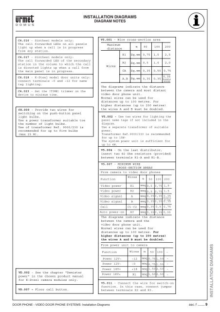
V5.001 - Wire cross-section area<br />
Maximum<br />
distance<br />
Wires<br />
R2<br />
CA<br />
A,B<br />
m<br />
R1 Sq.mm<br />
Sq.mm<br />
Sq.mm<br />
Sq.mm<br />
50<br />
0,75<br />
0,5 1,0<br />
0,35<br />
0,35<br />
100<br />
1,5<br />
0,50<br />
200<br />
2,5<br />
2,0<br />
0,75<br />
0,35 Double<br />
0,35<br />
wires<br />
The diagrams indicate the distance<br />
between the camera and most distant<br />
video door phone unit.<br />
Normal wires can be used for<br />
distances up to 100 metres. For<br />
higher distances (up to 200 metres)<br />
the wires A and B must be doubled.<br />
V5.002 - Use two wires for lighting the<br />
panel name tags if not included in the<br />
diagram.<br />
Use a separate transformer of suitable<br />
power.<br />
Transformer Ref.9000/230 is recommended<br />
for up to 15W-<br />
The system power unit is sufficient for<br />
up to 6W.<br />
V5.004 - On the last distributor,<br />
insert two 82 Ohm resistors (provided)<br />
between terminals R1-A and R1-B.<br />
V5.007 - MINIMUM WIRE<br />
CROSS-SECTION AREAS<br />
From camera to video door phones<br />
Function<br />
Video power<br />
Video power<br />
Video signal<br />
Video signal<br />
~0<br />
100<br />
mmq 0,35 0,35 0,35<br />
mmq 0,35 0,35 0,35<br />
The diagrams indicate the distance<br />
between the camera and the<br />
video door phone unit.<br />
Normal wires can be used for<br />
distances up to 100 metres. For<br />
higher distances (up to 200 metres)<br />
the wires A and B must be doubled.<br />
Power 18V=<br />
Wires<br />
mmq 0,75 1,50<br />
mmq 0,75 1,50<br />
mmq 1,50 2,50<br />
mmq 1,50 2,50<br />
double<br />
wires<br />
Call C1-C2 mmq 0,35 0,5 0,75<br />
Auto power-on AI mmq 0,35 0,35 0,35<br />
Function<br />
Power 18V=<br />
R1<br />
R2<br />
From power unit to camera<br />
Power 12V~<br />
Power 12V~<br />
A<br />
B<br />
Wires<br />
~12<br />
+18<br />
R1<br />
m<br />
m<br />
50<br />
200<br />
mmq 0,5 0,75 1,5<br />
mmq 0,5 0,75 1,5<br />
50<br />
100<br />
V5.011 - Connect the wire for switch-on<br />
function. In this case, connect jumper<br />
between terminals X2 and R3.<br />
-<br />
-<br />
-<br />
-<br />
-<br />
sec.1 −−−− 9<br />
INSTALLATION DIAGRAMS