DOOR PHONE - VIDEO DOOR PHONE SYSTEMS: Installation - Urmet
DOOR PHONE - VIDEO DOOR PHONE SYSTEMS: Installation - Urmet
DOOR PHONE - VIDEO DOOR PHONE SYSTEMS: Installation - Urmet

Create successful ePaper yourself
Turn your PDF publications into a flip-book with our unique Google optimized e-Paper software.
<strong>DOOR</strong> <strong>PHONE</strong> <strong>SYSTEMS</strong><br />
BASIC SYSTEM DIAGRAMS<br />
FUNCTION<br />
40 −−−− sec.1a<br />
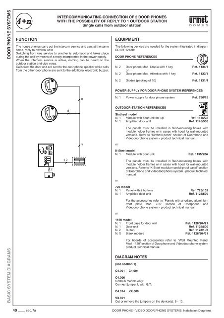
INTERCOMMUNICATING CONNECTION OF 2 <strong>DOOR</strong> <strong>PHONE</strong>S<br />
WITH THE POSSIBILITY OF REPLY TO 1 OUT<strong>DOOR</strong> STATION<br />
Single calls from outdoor station<br />
The house phones carry out the intercom service and can, at the same<br />
times, reply to external calls.<br />
Switching from one service to another is automatic and takes place<br />
during the call by means of a reply incorporated in the power supply.<br />
When the intercom service is active, nothing can be heard on the<br />
outdoor station and vice versa.<br />
Calls from the door unit are sent to the door phone speaker while calls<br />
from the other door phone are sent to the additional electronic buzzer.<br />
2<br />
12<br />
8<br />
8<br />
7<br />
EQUIPMENT<br />
The following devices are needed for the system illustrated in diagram<br />
SC101-1243B:<br />
<strong>DOOR</strong> <strong>PHONE</strong> REFERENCES<br />
N. 2 Door phone Mod. Utopia with 1 key Ref. 1134/1<br />
or<br />
N. 2 Door phone Mod. Atlantico with 1 key Ref. 1133/1<br />
N. 2 Diodes (packing of 10) Ref. 1131/4<br />
POWER SUPPLY FOR <strong>DOOR</strong> <strong>PHONE</strong> SYSTEM REFERENCES<br />
N. 1 Power supply for door phone system Ref. 786/15<br />
OUT<strong>DOOR</strong> STATION REFERENCES<br />
Sinthesi model<br />
N. 1 Module with door unit set-up Ref. 1145/22<br />
N. 1 Amplifi ed door unit Ref. 1145/500<br />
or<br />
The panels must be installed in fl ush-mounting boxes with<br />
module holder frames or in cases with hood for wall-mounted<br />
versions. Refer to “Sinthesi panel” section of Doorphone and<br />
Videodoorphone system - product technical manual.<br />
K-Steel model<br />
N. 1 Module with door unit Ref. 1155/22A<br />
or<br />
The panels must be installed in fl ush-mounting boxes with<br />
module holder frames or in cases with hood for wall-mounted<br />
versions. Refer to “K-Steel modular vandal-proof panel” section<br />
of Doorphone and Videodoorphone system - product technical<br />
manual.<br />
725 model<br />
N. 1 Panel with 2 buttons Ref. 725/102<br />
N. 1 Amplifi ed door unit Ref. 1128/500<br />
or<br />
For the accessories refer to “Panels with anodized aluminium<br />
front plate Mod. 725” section of Doorphone and<br />
Videodoorphone system - product technical manual.<br />
1128 model<br />
N. 1 Front case for door unit Ref. 1128/20-/21<br />
N. 1 Door unit Ref. 1128/500<br />
N. 2 Button Ref. 1128/1-/2<br />
N. X Blank module Ref. 1128/30-/31<br />
For boards of accessories refer to “Wall Mounted Panel<br />
Mod. 1128” section of Doorphone and Videodoorphone system<br />
product technical manual.<br />
DIAGRAM NOTES<br />
(see section 1)<br />
C4.001 C4.004<br />
C4.006<br />
Sinthesi models only:<br />
Connect jumper L with G/T.<br />
C4.014 VX.006<br />
VX.021<br />
Cut or remove the jumpers on the device(s): 6 - 10.<br />
<strong>DOOR</strong> <strong>PHONE</strong> - <strong>VIDEO</strong> <strong>DOOR</strong> <strong>PHONE</strong> <strong>SYSTEMS</strong>: <strong>Installation</strong> Diagrams