DOOR PHONE - VIDEO DOOR PHONE SYSTEMS: Installation - Urmet
DOOR PHONE - VIDEO DOOR PHONE SYSTEMS: Installation - Urmet
DOOR PHONE - VIDEO DOOR PHONE SYSTEMS: Installation - Urmet

Create successful ePaper yourself
Turn your PDF publications into a flip-book with our unique Google optimized e-Paper software.
<strong>DOOR</strong> <strong>PHONE</strong> <strong>SYSTEMS</strong><br />
BASIC SYSTEM DIAGRAMS<br />
FUNCTION<br />
6 −−−− sec.1b<br />
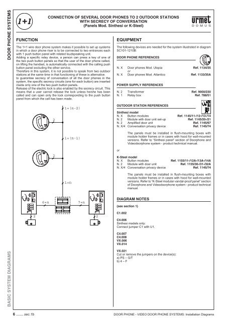
CONNECTION OF SEVERAL <strong>DOOR</strong> <strong>PHONE</strong>S TO 2 OUT<strong>DOOR</strong> STATIONS<br />
WITH SECRECY OF CONVERSATION<br />
(Panels Mod. Sinthesi or K-Steel)<br />
The 1+1 wire door phone system makes it possible to set up systems<br />
in which a door phone riser is to be connected to two entrances each<br />
with 1 push button panel with related loudspeaking unit.<br />
Adding a specifi c relay device, a person can press a key of one of<br />
the two push button panels so that the user of the door phone called,<br />
on lifting the handset, is automatically connected with the calling push<br />
button panel excluding the other service.<br />
Therefore in this system, it is not possible to speak from two outdoor<br />
stations at the same time in that functioning of these is alternative.<br />
to guarantee secrecy of conversation of all the door phones in the<br />
system, the specifi c secrecy circuits (one for each button) are inserted<br />
inside only one of the two push button panels.<br />
Release of the electric lock is also enabled by the secrecy circuit. This<br />
means that a user cannot release the lock unless he/she has been<br />
called and can open only the lock corresponding to the push button<br />
panel from which the call has been made.<br />
6+n<br />
2<br />
2<br />
1+(n-2)<br />
1+(n-1)<br />
1+n<br />
7+n<br />
2 2<br />
EQUIPMENT<br />
The following devices are needed for the system illustrated in diagram<br />
SC101-1210B:<br />
<strong>DOOR</strong> <strong>PHONE</strong> REFERENCES<br />
N. X Door phones Mod. Utopia Ref. 1134/35<br />
or<br />
N. X Door phones Mod. Atlantico Ref. 1133/35A<br />
POWER SUPPLY REFERENCES<br />
N. 2 Transformer Ref. 9000/230<br />
N. 1 Relay box Ref. 788/51<br />
OUT<strong>DOOR</strong> STATION REFERENCES<br />
Sinthesi model<br />
N. X Button modules Ref. 1145/11-/12-/13-/14<br />
N. 2 Module with door unit set-up Ref. 1145/20-/21<br />
N. 2 Amplifi ed door unit Ref. 1145/67<br />
N. X/4 Conversation privacy device Ref. 1145/74<br />
or<br />
The panels must be installed in fl ush-mounting boxes with<br />
module holder frames or in cases with hood for wall-mounted<br />
versions. Refer to “Sinthesi panel” section of Doorphone and<br />
Videodoorphone system - product technical manual.<br />
K-Steel model<br />
N. X Button modules Ref. 1155/11-/12A-/13A-/14A<br />
N. 2 Module with door unit Ref. 1155/30-/31-/32A<br />
N. X/4 Conversation privacy device Ref. 1145/74<br />
The panels must be installed in fl ush-mounting boxes with<br />
module holder frames or in cases with hood for wall-mounted<br />
versions. Refer to “K-Steel modular vandal-proof panel” section<br />
of Doorphone and Videodoorphone system - product technical<br />
manual.<br />
DIAGRAM NOTES<br />
(see section 1)<br />
C1.002<br />
C4.006<br />
Sinthesi models only:<br />
Connect jumper C1 with U1.<br />
C4.007<br />
C4.008<br />
VX.006<br />
VX.014<br />
VX.021<br />
Cut or remove the jumpers on the device(s):<br />
a) PS – G/T<br />
b) 4 – F<br />
<strong>DOOR</strong> <strong>PHONE</strong> - <strong>VIDEO</strong> <strong>DOOR</strong> <strong>PHONE</strong> <strong>SYSTEMS</strong>: <strong>Installation</strong> Diagrams