DOOR PHONE - VIDEO DOOR PHONE SYSTEMS: Installation - Urmet
DOOR PHONE - VIDEO DOOR PHONE SYSTEMS: Installation - Urmet
DOOR PHONE - VIDEO DOOR PHONE SYSTEMS: Installation - Urmet

Create successful ePaper yourself
Turn your PDF publications into a flip-book with our unique Google optimized e-Paper software.
BASIC DIAGRAMS<br />
EASIVOICE SYSTEM<br />
EASIVOICE<br />
FEATURES<br />
14 −−−− sec.2<br />
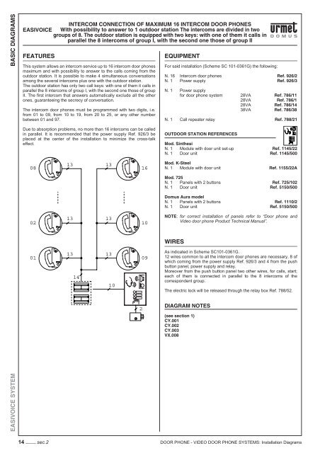
INTERCOM CONNECTION OF MAXIMUM 16 INTERCOM <strong>DOOR</strong> <strong>PHONE</strong>S<br />
With possibility to answer to 1 outdoor station The intercoms are divided in two<br />
groups of 8. The outdoor station is equipped with two keys: with one of them it calls in<br />
parallel the 8 intercoms of group I, with the second one those of group II<br />
This system allows an intercom service up to 16 intercom door phones<br />
maximum and with possibility to answer to the calls coming from the<br />
outdoor station. It is possible to make 4 simultaneous conversations<br />
among the several intercoms plus one with the outdoor station.<br />
The outdoor station has only two call keys: with one of them it calls in<br />
parallel the 8 intercoms of group I, with the second one those of group<br />
II. The fi rst intercom that answers automatically exclude all the other<br />
ones, guaranteeing the secrecy of conversation.<br />
The intercom door phones must be programmed with two digits, i.e.<br />
from 01 to 09, from 10 to 19, from 20 to 25, or any other number<br />
between 01 and 97.<br />
Due to absorption problems, no more than 16 intercoms can be called<br />
in parallel. It is recommended that the power supply Ref. 926/3 be<br />
placed at the center of the installation to minimize the cross-talk<br />
effect.<br />
08<br />
02<br />
01<br />
13<br />
13<br />
13<br />
14<br />
13<br />
13<br />
13<br />
10<br />
2<br />
16<br />
10<br />
09<br />
EQUIPMENT<br />
For said installation (Scheme SC 101-0361G) the following:<br />
N. 16 Intercom door phones Ref. 926/2<br />
N. 1 Power supply Ref. 926/3<br />
N. 1 Power supply<br />
for door phone system 28VA Ref. 786/11<br />
28VA Ref. 786/1<br />
28VA Ref. 786/14<br />
38VA Ref. 786/38<br />
N. 1 Call repeater relay Ref. 788/21<br />
OUT<strong>DOOR</strong> STATION REFERENCES<br />
Mod. Sinthesi<br />
N. 1 Module with door unit set-up Ref. 1145/22<br />
N. 1 Door unit Ref. 1145/500<br />
Mod. K-Steel<br />
N. 1 Module with door unit Ref. 1155/22A<br />
Mod. 725<br />
N. 1 Panels with 2 buttons Ref. 725/102<br />
N. 1 Door unit Ref. 5150/500<br />
Domus Aura model<br />
N. 1 Panels with 2 buttons Ref. 1110/2<br />
N. 1 Door unit Ref. 5150/500<br />
NOTE: for correct installation of panels refer to “Door phone and<br />
Video door phone Product Technical Manual”.<br />
WIRES<br />
As indicated in Scheme SC101-0361G.<br />
12 wires common to all the intercom door phones are necessary, 8 of<br />
which coming from the power supply Ref. 926/3 and 4 from the push<br />
button panel, power supply and relay.<br />
Moreover from the push button panel two other wires, for calls, start;<br />
each of them is connected in parallel to the 8 intercoms of the<br />
correspondent group.<br />
The electric lock will be released through the relay box Ref. 788/52.<br />
DIAGRAM NOTES<br />
(see section 1)<br />
CY.001<br />
CY.002<br />
CY.003<br />
VX.008<br />
<strong>DOOR</strong> <strong>PHONE</strong> - <strong>VIDEO</strong> <strong>DOOR</strong> <strong>PHONE</strong> <strong>SYSTEMS</strong>: <strong>Installation</strong> Diagrams