DOOR PHONE - VIDEO DOOR PHONE SYSTEMS: Installation - Urmet
DOOR PHONE - VIDEO DOOR PHONE SYSTEMS: Installation - Urmet
DOOR PHONE - VIDEO DOOR PHONE SYSTEMS: Installation - Urmet

You also want an ePaper? Increase the reach of your titles
YUMPU automatically turns print PDFs into web optimized ePapers that Google loves.
<strong>DOOR</strong> <strong>PHONE</strong> <strong>SYSTEMS</strong><br />
BASIC SYSTEM DIAGRAMS<br />
FUNCTION<br />
56 −−−− sec.1a<br />
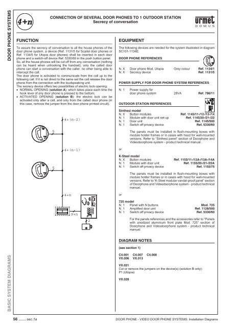
CONNECTION OF SEVERAL <strong>DOOR</strong> <strong>PHONE</strong>S TO 1 OUT<strong>DOOR</strong> STATION<br />
Secrecy of conversation<br />
To assure the secrecy of conversation to all the house phones of the<br />
door phone system, a device (Ref. 1131/5 for Scaitel door phones or<br />
Ref. 1134/5 for Utopia door phones) shall be inserted in each door<br />
phone and a switch-off device Ref. 5330/60 in the push button panel.<br />
So, all the house phones will be cut off from any conversation (nothing<br />
can be heard when unhooking the handset); only the called door<br />
phone can start a conversation with the caller, no other being able to<br />
intercept the call.<br />
The door phone is activated to communicate from the call up to the<br />
following call. If it is not direct to the same set the call release the door<br />
phone from the connection with the loudspeaking unit.<br />
The secrecy device offers two possibilities of electric lock opening:<br />
• NORMAL OPENING (solution A): which takes place each time the<br />
hook lever of any door phone is pressed to the bottom;<br />
• ACTIVATED OPENING (solution B): the electric lock can be<br />
activated only after a call, and only from the called door phone (in<br />
this case, remove the jumper from the door phone printed circuit).<br />
5<br />
5<br />
4+(n-2)<br />
4+(n-1)<br />
4+n<br />
9+n<br />
2<br />
EQUIPMENT<br />
The following devices are needed for the system illustrated in diagram<br />
SC101-1134E:<br />
<strong>DOOR</strong> <strong>PHONE</strong> REFERENCES<br />
N. X Door phone Mod. Utopia Grey colour Ref. 1134/1<br />
N. X Secrecy device Ref. 1131/5<br />
POWER SUPPLY FOR <strong>DOOR</strong> <strong>PHONE</strong> SYSTEM REFERENCES<br />
N. 1 Power supply for<br />
door phone system 28VA Ref. 786/11<br />
OUT<strong>DOOR</strong> STATION REFERENCES<br />
Sinthesi model<br />
N. X Button modules Ref. 1145/11-/12-/13-/14<br />
N. 1 Module with door unit set-up Ref. 1145/20-/21-/22<br />
N. 1 Door unit Ref. 1145/500<br />
N. 1 Switch off privacy device Ref. 5330/60<br />
or<br />
The panels must be installed in fl ush-mounting boxes with<br />
module holder frames or in cases with hood for wall-mounted<br />
versions. Refer to “Sinthesi panel” section of Doorphone and<br />
Videodoorphone system - product technical manual.<br />
K-Steel model<br />
N. X Button modules Ref. 1155/11-/12A-/13A-/14A<br />
N. 1 Module with door unit Ref. 1155/20-/21-/22A<br />
N. 1 Switch off privacy device Ref. 1155/75<br />
or<br />
The panels must be installed in fl ush-mounting boxes with<br />
module holder frames or in cases with hood for wall-mounted<br />
versions. Refer to “K-Steel modular vandal-proof panel” section<br />
of Doorphone and Videodoorphone system - product technical<br />
manual.<br />
725 model<br />
N. 1 Panel with N buttons Mod. 725<br />
N. 1 Amplifi ed door unit Ref. 1128/500<br />
N. 1 Switch off privacy device Ref. 5330/60<br />
For the panels references and the accessories refer to “Panels<br />
with anodized aluminium front plate Mod. 725” section of<br />
Doorphone and Videodoorphone system - product technical<br />
manual.<br />
DIAGRAM NOTES<br />
(see section 1)<br />
C4.001 C4.007 C4.008<br />
VX.006 VX.013<br />
VX.021<br />
Cut or remove the jumpers on the device(s) (solution B only):<br />
P1 (Utopia)<br />
VX.028<br />
<strong>DOOR</strong> <strong>PHONE</strong> - <strong>VIDEO</strong> <strong>DOOR</strong> <strong>PHONE</strong> <strong>SYSTEMS</strong>: <strong>Installation</strong> Diagrams