DOOR PHONE - VIDEO DOOR PHONE SYSTEMS: Installation - Urmet
DOOR PHONE - VIDEO DOOR PHONE SYSTEMS: Installation - Urmet
DOOR PHONE - VIDEO DOOR PHONE SYSTEMS: Installation - Urmet

You also want an ePaper? Increase the reach of your titles
YUMPU automatically turns print PDFs into web optimized ePapers that Google loves.
<strong>DOOR</strong> <strong>PHONE</strong> <strong>SYSTEMS</strong><br />
BASIC SYSTEM DIAGRAMS<br />
FUNCTION<br />
52 −−−− sec.1a<br />
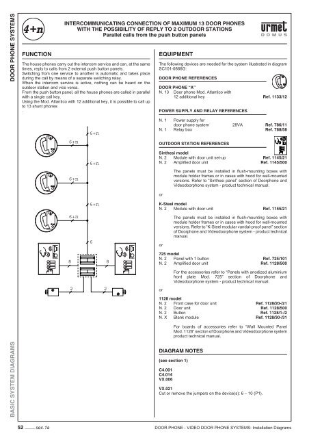
INTERCOMMUNICATING CONNECTION OF MAXIMUM 13 <strong>DOOR</strong> <strong>PHONE</strong>S<br />
WITH THE POSSIBILITY OF REPLY TO 2 OUT<strong>DOOR</strong> STATIONS<br />
Parallel calls from the push button panels<br />
The house phones carry out the intercom service and can, at the same<br />
times, reply to calls from 2 external push button panels.<br />
Switching from one service to another is automatic and takes place<br />
during the call by means of a separate switching relay.<br />
When the intercom service is active, nothing can be heard on the<br />
outdoor station and vice versa.<br />
From the push button panel, all the house phones are called in parallel<br />
with a single call key.<br />
Using the Mod. Atlantico with 12 additional key, it is possible to call up<br />
to 13 shunt phones<br />
.<br />
6+n<br />
6+n<br />
6+n<br />
6+n<br />
6+n<br />
6+n<br />
6<br />
8 8<br />
2 2<br />
EQUIPMENT<br />
The following devices are needed for the system illustrated in diagram<br />
SC101-0866G:<br />
<strong>DOOR</strong> <strong>PHONE</strong> REFERENCES<br />
<strong>DOOR</strong> <strong>PHONE</strong> “A”<br />
N. 13 Door phone Mod. Atlantico with<br />
12 additional key Ref. 1133/12<br />
POWER SUPPLY AND RELAY REFERENCES<br />
N. 1 Power supply for<br />
door phone system 28VA Ref. 786/11<br />
N. 1 Relay box Ref. 788/58<br />
OUT<strong>DOOR</strong> STATION REFERENCES<br />
Sinthesi model<br />
N. 2 Module with door unit set-up Ref. 1145/21<br />
N. 2 Amplifi ed door unit Ref. 1145/500<br />
or<br />
The panels must be installed in fl ush-mounting boxes with<br />
module holder frames or in cases with hood for wall-mounted<br />
versions. Refer to “Sinthesi panel” section of Doorphone and<br />
Videodoorphone system - product technical manual.<br />
K-Steel model<br />
N. 2 Module with door unit Ref. 1155/21<br />
or<br />
The panels must be installed in fl ush-mounting boxes with<br />
module holder frames or in cases with hood for wall-mounted<br />
versions. Refer to “K-Steel modular vandal-proof panel” section<br />
of Doorphone and Videodoorphone system - product technical<br />
manual.<br />
725 model<br />
N. 2 Panel with 1 button Ref. 725/101<br />
N. 2 Amplifi ed door unit Ref. 1128/500<br />
or<br />
For the accessories refer to “Panels with anodized aluminium<br />
front plate Mod. 725” section of Doorphone and<br />
Videodoorphone system - product technical manual.<br />
1128 model<br />
N. 2 Front case for door unit Ref. 1128/20-/21<br />
N. 2 Door unit Ref. 1128/500<br />
N. 2 Button Ref. 1128/1-/2<br />
N. X Blank module Ref. 1128/30-/31<br />
For boards of accessories refer to “Wall Mounted Panel<br />
Mod. 1128” section of Doorphone and Videodoorphone system<br />
product technical manual.<br />
DIAGRAM NOTES<br />
(see section 1)<br />
C4.001<br />
C4.014<br />
VX.006<br />
VX.021<br />
Cut or remove the jumpers on the device(s): 6 – 10 (P1).<br />
<strong>DOOR</strong> <strong>PHONE</strong> - <strong>VIDEO</strong> <strong>DOOR</strong> <strong>PHONE</strong> <strong>SYSTEMS</strong>: <strong>Installation</strong> Diagrams