II PRO PLUS Snowplow #64750/64999/66901/66974/66980
II PRO PLUS Snowplow #64750/64999/66901/66974/66980
II PRO PLUS Snowplow #64750/64999/66901/66974/66980

Create successful ePaper yourself
Turn your PDF publications into a flip-book with our unique Google optimized e-Paper software.
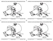
INSTALLATION INSTRUCTIONS4. Before assembly, apply grease to the pivot pin holesin each end of the pivot bar and to each pivot pin.5. Assemble the pivot plates to the ends of the pivotbar, using the appropriate plate orientation and holeposition for the confi guration determined in Step 2.Pivot Plate Mounting and Hole Positionsfor Configurations 1 & 2Pivot Plate A(Bevel Side Up)There are two pivot plates (A and B) which aremirror images of each other. They can be turnedupside down and switched from one side of thepivot bar to the other to provide two differentmounting positions.In each pivot plate mounting position, the pivotbar pins may be installed through one of the twolower holes in the pivot plates. This providesfour different height adjustment positions. Forall confi gurations, pivot pins must be positionedwith the notches in the pivot pins facing up andthe slots in the pivot pins aligned with the bottomholes at the rear of the pivot plates. Note that thepivot bar pins are never installed in either of thetwo upper holes in the pivot plates.Configuration 1Configuration 2Pivot Pin(Lubricate Pin)Pivot Plate B(Bevel Side Up)Pivot Plate Mounting and Hole Positionsfor Configurations 3 & 4Pivot Pin(Lubricate Pin)Pivot Plate B(Flat Side Up)Pivot Pin(Lubricate Pin)Configuration 3Configuration 4Pivot Pin(Lubricate Pin)Pivot Plate A(Flat Side Up)Lit. No. 66897, Rev. 07 10 June 15, 2010