II PRO PLUS Snowplow #64750/64999/66901/66974/66980
II PRO PLUS Snowplow #64750/64999/66901/66974/66980
II PRO PLUS Snowplow #64750/64999/66901/66974/66980

You also want an ePaper? Increase the reach of your titles
YUMPU automatically turns print PDFs into web optimized ePapers that Google loves.
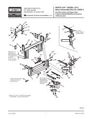
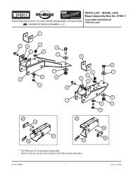
INSTALLATION INSTRUCTIONSCHAIN TO A-FRAME1. Use a hook or piece of wire to pull the end of thechain through the plastic tube. The end link of thechain must be fully exposed.PIVOT BAR TO A-FRAME1. Insert one end of pivot bar into rectangular sloton one side of rear of A-frame as far as possible.Pivot bushing must face away from A-frame.2. Rotate pivot bar until level with A-frame and slideother end into corresponding rectangular slot.PlasticTube3. Align center holes and insert 1" x 7" cap screw asshown in illustration.Pull chain throughwith hook or wireEnd linkfully exposed4. Install 1" jam nut and tighten to 25 ft-lb thenloosen 1/16 turn.5. Hold 1" cap screw and jam nut to prevent rotationand install 1" locknut. Tighten locknut securelyagainst jam nut.NOTE: When properly adjusted, pivot bar shouldpivot freely without any looseness.2. Insert ends of the 3/8" x 1-1/2" U-bolt throughthe chain and then down through the holes in thechain bracket on the A-frame and secure with two3/8" locknuts.1" Locknut1" Jam Nut RectangularSlot3. Repeat Steps 1 and 2 for the other side.Chains withPlastic TubesPivot BarUBoltsA-FramePivotBushing1" x 7"Cap Screw3/8"LocknutsChainBracketLit. No. 66897, Rev. 07 8 June 15, 2010