
You also want an ePaper? Increase the reach of your titles
YUMPU automatically turns print PDFs into web optimized ePapers that Google loves.
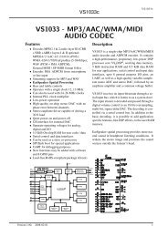
<strong>VS1000</strong>6 <strong>VS1000</strong> FUNCTIONAL BLOCKSUARTAn asynchronous serial port is used for debugging and special applications. The default speedis 115200 bps. RX and TX pins can also be used for general-purpose I/O when the UART isnot required.SPIA synchronous serial port peripheral is used for SPIEEPROM boot, and can be used to accessother SPI peripherals (for example LCD or SED) by using another chip select. The SPI is onlyused for boot if the XCS pin has a high level after reset (pull-up resistor attached). These pinscan also be used for general-purpose I/O when the SPI is not required.The default player uses SI and SO for LED outputs.NAND FLASH InterfaceThe NAND FLASH peripheral calculates a simple error-correcting code (ECC), and automatessome of the communication with a NAND FLASH chip. The firmware uses the peripheral toaccess both small-page (512+16 B pages) and large-page (2048+64 B pages) NAND FLASHchips. The first sector in the FLASH tells the firmware how it should be accessed.The NAND FLASH interface pins can also be used as general-purpose I/O. The default firmwareuses GPIO0_[4:0] for keys, and GPIO0_[7:6] for other purposes. Pull-up and pull-down resistorsmust be used for these connections so that the data transfer to and from the NAND FLASHisn’t disturbed when keys are pressed.USBThe USB peripheral handles USB 1.1 Full Speed harware protocol. Low speed communicationis not supported, but is correctly ignored. The USBP pin has a software-controllable 1.5kΩpull-up.A control endpoint (1 IN and 1 OUT) and upto 6 other endpoints (3 IN and 3 OUT) can beused simultaneously. Bulk, interrupt, and isochronous transfer modes are selectable for eachendpoint. USB receive from USB host to device (OUT) uses a 2 KiB buffer, thus allowing veryhigh transfer speeds. USB transmit from device to USB host (IN) also uses a 2 KiB buffer andallows all IN endpoints to be ready to transmit simultaneously. Double-buffering is also possible,but not usually required.The firmware uses the USB peripheral to implement both USB Mass Storage Device and USBAudio Device. Which device is activated depends on the state of GPIO0_6 when the USBconnection is detected. If GPIO0_6 has a pull-up resistor, <strong>VS1000</strong> appears as an USB AudioDevice. If GPIO0_6 has a pull-down resistor, <strong>VS1000</strong> appears as an USB Mass StorageDevice.Version: 1.43, 2013-05-28 16