
Create successful ePaper yourself
Turn your PDF publications into a flip-book with our unique Google optimized e-Paper software.
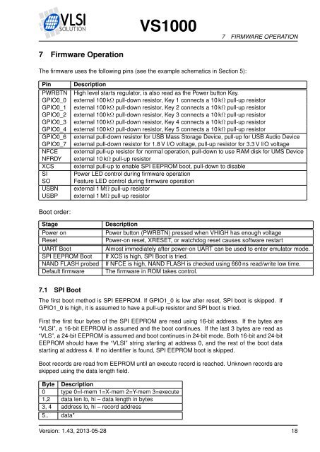
<strong>VS1000</strong>7 FIRMWARE OPERATION7 Firmware OperationThe firmware uses the following pins (see the example schematics in Section 5):PinPWRBTNGPIO0_0GPIO0_1GPIO0_2GPIO0_3GPIO0_4GPIO0_6GPIO0_7NFCENFRDYXCSSISOUSBNUSBPDescriptionHigh level starts regulator, is also read as the Power button Key.external 100 kΩ pull-down resistor, Key 1 connects a 10 kΩ pull-up resistorexternal 100 kΩ pull-down resistor, Key 2 connects a 10 kΩ pull-up resistorexternal 100 kΩ pull-down resistor, Key 3 connects a 10 kΩ pull-up resistorexternal 100 kΩ pull-down resistor, Key 4 connects a 10 kΩ pull-up resistorexternal 100 kΩ pull-down resistor, Key 5 connects a 10 kΩ pull-up resistorexternal pull-down resistor for USB Mass Storage Device, pull-up for USB Audio Deviceexternal pull-down resistor for 1.8 V I/O voltage, pull-up resistor for 3.3 V I/O voltageexternal pull-up resistor for normal operation, pull-down to use RAM disk for UMS Deviceexternal 10 kΩ pull-up resistorexternal pull-up to enable SPI EEPROM boot, pull-down to disablePower LED control during firmware operationFeature LED control during firmware operationexternal 1 MΩ pull-up resistorexternal 1 MΩ pull-up resistorBoot order:StagePower onResetUART BootSPI EEPROM BootNAND FLASH probedDefault firmwareDescriptionPower button (PWRBTN) pressed when VHIGH has enough voltagePower-on reset, XRESET, or watchdog reset causes software restartAlmost immediately after power-on UART can be used to enter emulator mode.If XCS is high, SPI Boot is tried.If NFCE is high, NAND FLASH is checked using 660 ns read/write low time.The firmware in ROM takes control.7.1 SPI BootThe first boot method is SPI EEPROM. If GPIO1_0 is low after reset, SPI boot is skipped. IfGPIO1_0 is high, it is assumed to have a pull-up resistor and SPI boot is tried.First the first four bytes of the SPI EEPROM are read using 16-bit address. If the bytes are“<strong>VLSI</strong>”, a 16-bit EEPROM is assumed and the boot continues. If the last 3 bytes are read as“VLS”, a 24-bit EEPROM is assumed and boot continues in 24-bit mode. Both 16-bit and 24-bitEEPROM should have the “<strong>VLSI</strong>” string starting at address 0, and the rest of the boot datastarting at address 4. If no identifier is found, SPI EEPROM boot is skipped.Boot records are read from EEPROM until an execute record is reached. Unknown records areskipped using the data length field.Byte Description0 type 0=I-mem 1=X-mem 2=Y-mem 3=execute1,2 data len lo, hi – data length in bytes3, 4 address lo, hi – record address5.. data*Version: 1.43, 2013-05-28 18