
Create successful ePaper yourself
Turn your PDF publications into a flip-book with our unique Google optimized e-Paper software.
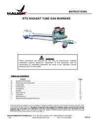
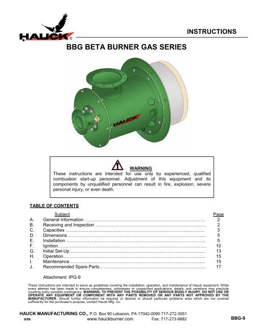
Page 2<strong>BBG</strong>-9WARNINGThis equipment is potentially dangerous with the possibility of serious personal injuryand property damage. Hauck Manufacturing Company recommends the use of flamesupervisory equipment and fuel safety shutoff valves. Furthermore, Hauck urges rigidadherence to National Fire Protection Association (NFPA) standards and insuranceunderwriter’s requirements. Operation and regular preventative maintenance of thisequipment should be performed only by properly trained and qualified personnel.Annual review and upgrading of safety equipment is recommended.A. GENERAL INFORMATIONThe <strong>BBG</strong> burners are baffle type burners designed for low pressure air operation in a widerange of applications. Available with alloy tile for ambient combustion air only for temperaturesup to 1800°F (980°C), and refractory tile for temperatures up to 2800°F (1540°C). With arefractory tile, the 1000 and 2000 series can operate with air preheat temperatures up to 600°F(315°C), and the 3000 series can operate with air preheat temperatures up to 900°F (480°C).The <strong>BBG</strong> burners fire any clean industrial fuel gas. Capacities range from 2.2 million to 87million Btu/hr (645 to 25,500 kW). Higher capacity models are available upon request. The <strong>BBG</strong>burner flame shapes are well-defined throughout the burner’s operating range. Two refractorytile options are available: the diverging tile which produces a slow mixing, long wide flame, andthe converging tile which produces a shorter, narrower, more well-defined flame.Direct spark ignition is available on the <strong>BBG</strong>_ 204 through _212 burners, while gas pilot ignitionis available on all <strong>BBG</strong> burners. On ratio turndown is approximately 8:1 on natural gas. Ifoperating with excess air, thermal turndown is greater.B. RECEIVING AND INSPECTIONUpon receipt, check each item on the bill of lading and/or invoice to determine that allequipment has been received. A careful examination of all parts should be made to ascertain ifthere has been any damage in shipment.IMPORTANTIf the installation is delayed and the equipment is stored outside,provide adequate protection as dictated by climate and period ofexposure. Special care should be given to all motors and bearings, ifapplicable, to protect them from rain or excessive moisture.
C. <strong>BURNER</strong> CAPACITIES (Continued)Page 4<strong>BBG</strong>-9MODEL NUMBERSPECIFICATIONS_ _04 _ _06 _ _08 _ _10 _ _12 _114 _118 _124HIGHMax. Input @ 10% Excess Air (kW) 582 1,300 2,330 3,600 5,240 7,140 11,800 23,000Max. Air Flow @ 3450 Pa (nm 3 /hr) 611 1,360 2,450 3,780 5,490 7,500 12,300 24,200FI Max. Excess Air (%) 400 260 800 275 320 400 650 600RE Flame Length @ Max. Input (m) 1.4 1.8 2.1 2.8 3.1 3.3 4.7 7.2LOWFIREMax. Input @ 10% Excess Air (kW) 85 183 344 529 767 1,030 1,720 3,360Air Flow @ 75 Pa (nm 3 /hr) 89 191 356 552 801 1,090 1,800 3,540Max. Excess Air (%) 100 80 240 100 120 150 280 100NOTES:1. Capacities based on natural gas with LHV of 36.74 MJ/nm 3 0.59 S.G., and a stoichiometric air/gas ratioof 9.74:1 with burner firing into chamber under no pressure.2. Air and gas flows based on 0°C @ sea level.3. Static air pressures measured at the burner air inlet pressure tap.4. Flame lengths measured from the end of converging tile; for a diverging tile (available for _ _06 through_118), add 18% to the flame length.5. To determine flame lengths at different excess air values, use the following equation:6. All data based on industry standard air and gas piping practices.7. Burners can be operated up to a static air pressure of 5170 Pa; consult Hauck.Table 2. Metric Burner Capacities
Page 5<strong>BBG</strong>-9D. DIMENSIONSSee appropriate Dimension sheet for detailed dimensional information.E. INSTALLATIONNOTEIf the burner utilizes an ultraviolet (UV) scanner for flamesupervision, the burner should be positioned so that the UVscanner is located above the horizontal centerline of the burner toprevent moisture and airborne debris from setting into the UVscanner port and blocking the lens.Hauck <strong>BBG</strong> burners must be mounted on properly braced, rigid furnace structures capable ofsupporting the burner and tile weight (see Table 3).Approx.BurnerNet WeightApprox.Refractory TileNet WeightApprox.Alloy TileNet WeightBurner Model<strong>BBG</strong>_ _04 100 lb (45 kg) 95 lb (43 kg) 45 lb (20 kg)<strong>BBG</strong>_ _06 350 lb (159 kg) 140 lb (63 kg) 95 lb (43 kg)<strong>BBG</strong>_ _08 350 lb (159 kg) 140 lb (63 kg) 95 lb (43 kg)<strong>BBG</strong>_ _10 370 lb (168 kg) 210 lb (95 kg) 110 lb (50 kg)<strong>BBG</strong>_ _12 425 lb (193 kg) 300 lb (136 kg) 130 lb (59 kg)<strong>BBG</strong>_ 114 580 lb (263 kg) 510 lb (231 kg) 150 lb (68 kg)<strong>BBG</strong>_ 118 1,200 lb (544 kg) 540 lb (245 kg) 195 lb (88 kg)<strong>BBG</strong>_ 124 3,350 lb (1,520 kg) 1,200 lb (544 kg) 275 lb (125 kg)Table 3. Burner and Tile WeightsBurner Mounting (see Figure 1 for Refractory Tile, Figure 2 for Alloy Tile)1. Furnish an opening in the furnace shell 1/2" (13mm) larger than the outside diameter of theburner tile.2. Weld the appropriate size studs of appropriate length to the furnace shell to accept the tilemounting flange.3. From inside the furnace, remove poured refractory, brick, ceramic fiber blanket or board bymaking a round cut-out 3" (76mm) larger than the outside diameter of the burner tile.4. Slip the tile mounting gasket over the studs on the furnace shell.5. Install the burner tile on the furnace shell and secure with appropriate lock washers andnuts.6. Place the tile cushion gasket into the recess in the burner tile.7. Slip the burner mounting gasket over the studs on the burner tile flange.8. Install the <strong>BBG</strong> burner on the burner tile flange and secure with appropriate lock washersand nuts.
Page 6<strong>BBG</strong>-9W7324(NOT TO SCALE)Figure 1. Burner Installation With Refractory TileW7783(NOT TO SCALE)Figure 2. Burner Installation With Alloy Tile
Page 7<strong>BBG</strong>-99. From inside the furnace, pack ceramic fiber blanket rated for a higher temperature than thefurnace into the annular opening between the burner tile and the furnace wall insulation orrefractory. It is important that the fiber is well packed to ensure that the furnace shell, tileflange, burner flange, and associated gaskets are not damaged. Fiber must be repackedafter initial firing of the <strong>BBG</strong> burner.NOTEIf the <strong>BBG</strong> burner was not supplied with a self-supportingrefractory or alloy tile, then a field poured refractory port must beinstalled. Installation requirements are available for field pouredrefractory ports for <strong>BBG</strong> burners (reference Drawing X4195 andX5565), including removable, reusable metal mandrels; consultHauck.X4195(NOT TO SCALE)Figure 3. Field Poured Refractory Port <strong>BBG</strong>_ _04 Through _118X5565(NOT TO SCALE)Figure 4. Field Poured Refractory Port <strong>BBG</strong>_124
Page 8<strong>BBG</strong>-9Air and Fuel ConnectionsNOTEAll piping must be properly supported and aligned to avoid stresseson the burner and associated equipment. Hauck recommends thatflexible connections be used on all air and fuel lines to isolate theburner from piping movement due to expansion, contraction, andvibration.1. Install the air line to the burner body using a flexible connection. Avoid elbows and abruptdirectional changes in the piping where possible as turbulence can affect flow measurementaccuracy, and reduce pressure at the burner.2. If necessary, the gas connection on direct spark ignited <strong>BBG</strong>_ 204 through _ 212 burnerscan be rotated in 45° increments as follows:a. Remove the screws and lock washers holding the gas inlet to the burner body.b. Rotate the gas inlet until it is in the desired location.c. Make sure the gasket between the gas inlet and the burner body is properly seated.d. Replace the washers and screws and tighten.3. Install the gas line to the gas inlet using a flexible connection. Avoid elbows and abruptdirectional changes in the piping where possible as turbulence can affect flow measurementaccuracy, and reduce pressure at the burner.4. For <strong>BBG</strong> burners using gas pilot ignition:a. <strong>BBG</strong>_ 104 through _118 Gas PilotInstall the pilot tip in the connection located above the burner center line on the burnerbody. Connect pilot air and gas to the appropriate connections on the gas pilot.Consult the appropriate dimensional sheet and instructions that accompany the pilotfor additional information (IPG-9).b. <strong>BBG</strong>_124 Forced Air Premix PilotInstall the air/fuel premix outlet of the pilot manifold assembly to the pilot assembly.Connect pilot air and gas to the appropriate connections on the pilot manifold.NOTESize the pilot gas supply line to avoid excessive pressure drops. Forsupply lines up to 25 ft (7.6m) use 1/2" (DN 15) pipe; from 25 to 100ft (7.6 – 30m) use 3/4" (DN 20) pipe. Prior to connecting to the pilotgas manifold, the gas line should be purged to remove debris.NOTEAll burner models are provided with two sets of connections forobservation port, pilot and UV scanner mounting. If the main airconnection is at 6 or 12 o’clock, the accessory ports at either 3 or 9o’clock can be used. However, both the pilot and UV scannermust be in adjacent ports on the same side of the burner. If themain air connection is at 3 or 9 o’clock, use the pilot and UV scannerconnection ports located 180° from the main air connection. Neitherthe pilot nor the UV scanner should be located below the horizontalcenterline of the burner, where they could be adversely affected bydirt and debris.
Page 9<strong>BBG</strong>-9NOTEThe <strong>BBG</strong>_124 UV scanner connections are positioned at 45°and 225° clockwise from the main air connection center line.Use guidelines in previous note to choose UV scanner port.5. If a UV scanner is used, install it in the correct accessory port adjacent to the pilotconnection. Provide a clean, ambient air source for the UV scanner air purge by connectingthe main air line to the 1/8 NPT (DN 6) air connection on the UV scanner adapter using 3/8"(1mm) OD tubing and a suitable isolating valve.6. If the observation port, pilot, and UV scanner must be relocated during installation due tointerferences with piping, etc., the alternate ports can be utilized as follows (see Figure 5):a. Remove the pipe plugs (or caps) from the alternate port connections.b. Remove the ceramic fiber insulation from the ports.c. Insert screwdriver or rod into each port and gently tamp on the plug of high temperaturecement to dislodge the plug. Use caution not to chip away refractory fromthe opening in the refractory ring.d. Insert the ceramic fiber insulation into the original ports. Failure to insert ceramicfiber insulation into the unused ports may result in damage to the outer metalburner housing.e. Secure the pipe plugs (or caps) in the original port connections.f. Install a thin coat of high temperature cement (Hauck recommends Resco Adamant orequivalent) over the original ports from the inside of the burner to contain the ceramicfiber insulation.Y7205(NOT TO SCALE)Figure 5. Port Sealing Arrangement7. Verify that all piping connections are tight. Close all unused port openings on the burnerbody.8. Inspect all bolted joints on the burner to ensure that all fasteners are tight and gaskets areproperly seated.
Page 10<strong>BBG</strong>-9CAUTIONIn order to ensure an adequate seal, it is important that the burner backplatebolts be sufficiently tight. Before any attempt is made to start the burner,check to ensure that the bolts are sufficiently tight and conduct a gas leaktest. Failure to check and ensure that a satisfactory seal exists byconducting a leak test could result in the formation of a hazardous gasleakage condition. Whenever burner internals are removed for cleaning orreplacement, be sure to tighten the backplate bolts and conduct a gas leaktest.F. IGNITIONWARNINGAdjustment of this equipment by unqualified personnelcan result in fire, explosion, severe personal injury, oreven death.<strong>BBG</strong> burners are available with a gas pilot igniter or an air-cooled spark igniter. For eitherigniter, a 5000/6000 volt standard coil type ignition transformer or a half-wave "spark blind" solidstate type transformer can be utilized. Both transformers yield satisfactory results, however, thestandard coil type transformer provides reliable ignition over a wider range of air/fuel ratios thanthe half-wave type.WARNINGWhen using a standard coil ignition transformer,provisions must be made to eliminate the ignitionspark falsely satisfying the “flame on” UV scanner.Hauck designed flame supervisory panels accomplishthis by “timing out” the spark transformer after a short(10 seconds for most applications) trial for ignition.NOTEManual ignition or torch lighting is not recommended.For Gas Pilot Ignited Burners (<strong>BBG</strong>_ 104 through _118):1. Ensure that the gas pilot igniter is threaded tightly into the pilot port.2. Connect the ignition wire from the transformer to the spark plug on the gas pilot igniter. Asnap-on ignition type connector is recommended.3. If using a Hauck IPG spark ignited gas pilot, see IPG-9 attached to these instructions fordetailed operating instructions. Otherwise, see pilot vendor literature.
Page 11<strong>BBG</strong>-9For Forced Air Premix Pilot Ignited Burners (<strong>BBG</strong>_124 only):1. The maximum gas supply pressure at the inlet to the pilot gas regulator is 5 psig (35 kPa).The regulated pilot gas supply to the gas limiting valve must be a nominal 20"wc (5 kPa).2. The pilot gas regulator should be back-loaded from the chamber into which the burner isfiring to ensure optimum pilot performance.3. Ensure that the spark wire gap in the pilot is 1/8" (3mm) as shown in Figure 6. If the gapmust be adjusted, carefully remove the pilot internals and bend the spark wire as required.Reinsert the pilot internals and check the gap. For field adjustment, a U.S. 5¢ coin with 0.08"(2mm) thickness can be used as a gauge for adjusting the spark gap.Figure 6. Pilot and Manifold Assembly Setup4. Ensure that premix pilot igniter is bolted securely to burner backplate.X7802(NOT TO SCALE)5. Connect the ignition wire from the transformer to the spark plug on the premix pilot igniter. Asnap-on ignition type connector is recommended.6. Set pilot air butterfly valve at position 5 (i.e., half open). Pilot air supply pressure at the inletof the air butterfly valve must be a nominal 14"wc (3.5 kPa).7. Remove the hex screw cap from the gas limiting valve and set the adjustment screw 4 turnsfrom the fully closed position. This initial setting may be changed during final pilotadjustment; clockwise rotation decreases gas flow and counterclockwise rotation increasesgas flow. Replace the hex screw cap when adjustment is complete.8. Remove the protective cover from the pilot gas regulator (located upstream of the limitinggas valve) and rotate the adjustment screw until it is in the middle of it’s adjustment range.This is only a preliminary setting and may also be changed to provide optimum pilotperformance.
Page 13<strong>BBG</strong>-9G. INITIAL SETUP<strong>BBG</strong> burners typically operate with automatic control systems. The burners are capable ofproportional control over their entire capacity range. In a typical system, ignition will bepreceded by a series of steps.CAUTIONInitial adjustment and burner start-up should beundertaken only by trained and experiencedpersonnel familiar with combustion systems,control and safety circuitry and overall installationprocedures.CAUTIONEnsure that all safety equipment and limits areworking properly before proceeding.CAUTIONFailure to achieve ignition of pilot or main flame within asafe period (10 seconds) could result in a build-up of acombustible gas mixture which could lead to an explosion.In the event that the pilot or main flame does not light withinthe above time period, shut off fuel valves and re-purge thechamber before attempting further adjustment.NOTEThe burner tile should not be subjected to rapid heatincreases at initial start-up. Allow low fire drying for atleast 6 – 8 hours before exposing the system to normalfiring operation. Thereafter, if the tile is exposed toexcessive moisture or extended periods of dampness,allow at least 30 minutes of low fire drying beforebeginning normal operation.1. Once installed, the burner is ready for initial setup. The specific operation of the burner willdepend on the individual system components in the entire combustion system. Refer to theinstruction sheets that accompany the individual components.2. Combustion air pressure should be set at the combustion air control valve. Typicalcombustion air pressure range from a minimum of approximately 0.17 osig (75 Pa) to amaximum of 8 osig (3450 Pa) static pressure at the burner static pressure test pointsprovided. Hauck recommends that the combustion air setting remain at minimum until theburner has been ignited (refer to the appropriate capacity sheet for burner air flow at low fireconditions).3. Gas pressure should be set at the gas control valve. Nominal natural gas pressure requiredat the burner is approximately 4 osig (1740 Pa). Actual gas pressure required may vary(refer to the appropriate capacity sheet for burner gas flow at low fire conditions).4. If not previously completed, refer to Section F for setup of the gas pilot igniter or the aircooleddirect spark igniter.
Page 14<strong>BBG</strong>-95. Once the igniter is set and the initial gas and air adjustments are made, the burner can beignited as follows:a. Be sure that all fuel shutoff valves are closed and all control valves are in the low fireposition.b. Start the combustion air blower.For Gas Pilot Ignition:c. Ensure that the pilot automatic safety solenoid valves and the pilot manual gas valve areclosed.d. Turn the pilot manual air valve to the full open position.e. Energize the igniter transformer.f. Open the pilot gas automatic safety shutoff solenoid valves and the pilot manual gasvalve.g. Once the pilot flame has been established (confirm using observation port or UV flamesupervision), de-energize the ignition transformer.h. Open (energize) the main automatic gas safety shutoff valves.i. Once flame has been established, de-energize the ignition transformer, close the pilotmanual valve, and leave the manual pilot air valve open.j. Proceed to ignite all burners (if applicable) per the above procedure.For Air-Cooled Direct Spark Ignition:k. Energize the ignition transformer.l. Open (energize) the main automatic gas safety shutoff valves.m. Once flame has been established de-energize the ignition transformer.n. Proceed to ignite all burners (if applicable) per the above procedure.6. When all burners are ignited, increase the combustion air to the high fire position (refer toappropriate capacity sheet for burner air flow at high fire conditions).7. When high fire combustion air is set, adjust the gas control valve (limiting gas valve orautomatic butterfly valve) to achieve the desired gas flow at high fire (refer to appropriatecapacity sheet for burner gas flow at high fire conditions).8. Verify air/fuel ratio using orifice meters in the air and gas lines. Static air pressure at theburner air inlet can be related to air flows if an air orifice meter is not available.9. Drive the burner to the low fire position and verify that the settings are consistent. Repeatsteps 6 through 9 as necessary until high and low fire settings remain constant.10. Lock all control motor linkage or direct-couplings in place and return all control systemfunctions to normal, if changed during initial adjustments.11. To shut down the burner system:a. Return the burner(s) to the low fire position.b. Close all fuel shutoff valves.c. Allow the furnace to cool to 800°F (425°C) or less before shutting off the combustion airblower.
Page 15<strong>BBG</strong>-9H. OPERATIONOnce properly installed, ignited and fired, the burner is ready for operation. The operation of theburner will depend on the specific items in the combustion control system and the application ofthe burners. Refer to the instruction sheet that accompanies each item. The burner shouldalways be ignited under low fire conditions. When the burner is firing, the spark igniter or gaspilot should be shut off.NOTEIf the refractory in the burner is exposed to excessivemoisture or extended periods of dampness, allow at least30 minutes of low fire drying before beginning normaloperation. Failure to do so can cause moisture presentto expand rapidly, causing damage to the refractory.I. MAINTENANCEHauck Beta Burners have been carefully engineered to provide dependable performance whilerequiring low maintenance. As with any product, it is very important to follow operatinginstructions and all procedures carefully to obtain optimum performance. Please refer to theapplicable Beta Burner Parts List to become familiar with the various burner components andassemblies.CAUTIONBe sure burner internals have cooled sufficiently beforeattempting to disassemble any components. Use carewhen separating gasket surfaces to avoid damage to thegaskets.1. Burner components which should be checked periodically and cleaned, if necessary,include:Gas Body Assembly (All Models)a. Disconnect the gas line.b Remove the air-cooled direct spark igniter (if applicable).c Remove front set of hex bolts from air body backplate.d. Remove gas inlet from burner.e. Inspect internal parts. Clean the interior walls of gas body assembly and gas tubeassembly of any residue.f. Check condition of internal baffle and clean main air openings in baffle, if needed.g. Reinsert gas making sure that the gasket is properly seated and connectionsproperly oriented.h. Replace hex bolts and securely tighten.i. Reconnect the gas line.
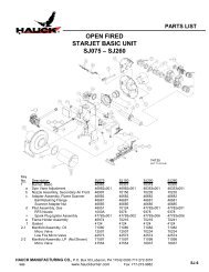
2. Replacement of Internal BafflePage 16<strong>BBG</strong>-9In certain situations, it may be become necessary or desirable to replace the internal baffle ofthe burner. The baffle on Beta Burner 1_00 series models is made of high temperature stainlesssteel, while the baffles on 2_00 and 3_00 series burners are made of high temperaturerefractory. In order to replace the internal baffle, use the following procedure:a. Disconnect fuel line.b. Loosen the backplate bolts.c. Remove burner internals after breaking the seal between the internal baffle and themain tile. Be careful not to damage the internal body liners (<strong>BBG</strong> 3_00 models).d. For 1_00 series models (stainless steel baffle):(1) Remove (3) 1/4" hex head cap screws and baffle from gas tube.(2) Place new baffle on gas tube.(3) Replace hex screws and tighten.e. For 2_00 and 3_00 series models (refractory baffle):(1) If baffle has remained attached to gas tube, separate baffle from tube.(2) If baffle has remained inside burner after removal of gas tube, break seal aroundbaffle edges and remove from burner.(3) Clean any residue from gas tube.(4) Replace Fiberfrax gasket around gas tube.(5) Carefully place new baffle on gas tube and press fit.f. For all models:(1) Coat outer edges of new baffle with 1/8" (3mm) thick layer of high temperaturecoating cement (Hauck recommends Fiberfrax QF-150 or equivalent).(2) Replace the existing gasket (if undamaged).(3) Carefully replace entire assembly, making sure baffle is centered in burner and hasseated against refractory step.(4) Reattach internal assembly to the main air body by tightening the backplate bolts.(5) Torque the backplate bolts to 30 ft-lb (41 Nm).(6) Reconnect the seal at the backplate bolts and any other joints where the possibilityof a gas leak exists.CAUTIONFailure to check and ensure that a satisfactory seal exists byconducting a gas leak test could result in a hazardous condition.3. Replacement of Self-Supporting Refractory or Alloy TileTiles should be checked for coke/residue build-up or damage. If this cannot be done from insidethe furnace, it will be necessary to gain access to the tile by removing the burner backplateassembly as described in step 2. Should it ever become necessary to replace the burner tile,use the following procedure:a. Disconnect all fuel and air piping from burner.b. Remove UV scanner, and gas pilot or direct spark igniter from accessory ports (ifapplicable).c. Support the burner weight before loosening mounting nuts.d. Loosen the burner mounting nuts from the burner mounting studs and remove theburner assembly from the furnace.e. Loosen and remove the tile mounting nuts from the mounting plate studs.f. Remove the existing burner tile from the furnace wall and clean the tile port opening.g. Inspect the furnace wall insulation or refractory in the area surrounding the tile andrepair any damage.
Page 17<strong>BBG</strong>-9h. Replace the burner tile mounting gasket, if necessary.i. Replace the tile cushion gasket into the recess in the burner tile, if necessary.j. Mount the new burner tile.k. Replace tile mounting nuts and tighten.l. Reinstall all UV scanner, and gas pilot or direct spark igniter in appropriate ports (ifapplicable).m. Reconnect all fuel and air piping to the burner and check for gas leaks before restartingthe burner.J. RECOMMENDED SPARE PARTS LISTItem Qty. Part Number Description1 1 See Parts List Gas Pilot, Igniter (If Applicable)2 1 See Parts List Direct Spark Igniter Assembly (If Applicable)3 1 See Parts List UV ScannerTable 4. Recommended Spare Parts
Page 18<strong>BBG</strong>-9This page left intentionally blank.HAUCK MANUFACTURING CO., P.O. Box 90 Lebanon, PA 17042-0090 717-272-3051www.hauckburner.com Fax: 717-273-9882
INSTRUCTIONSIPG IGNITION <strong>GAS</strong> PILOTSBACK-LOADED <strong>GAS</strong>WARNINGThese instructions are intended for use only by experienced, qualifiedcombustion start-up personnel. Adjustment of this equipment and itscomponents by unqualified personnel can result in fire, explosion, severepersonal injury, or even death.TABLE OF CONTENTSSubjectPageA. General Information ……………………………………………………….…..….……. 2B. Receiving and Inspection ………………………………………….…….…...…….….. 2C. Capacities ………….……………………………………………………………………. 3D. Dimensions …………….………………………………………………………………... 4E. Installation ……………………………………………………………………………….. 8F. Ignition……………………………………………………………………………………. 8G. Operation…………………………………………………………………………………. 11H. Shutoff Valve Leak Testing…………………………………………………………….. 11I. Maintenance……………………………………………………………………………… 13These instructions are intended to serve as guidelines covering the installation, operation, and maintenance of Hauck equipment. Whileevery attempt has been made to ensure completeness, unforeseen or unspecified applications, details, and variations may precludecovering every possible contingency. WARNING: TO PREVENT THE POSSIBILITY OF SERIOUS BODILY INJURY, DO NOT USE OROPERATE ANY EQUIPMENT OR COMPONENT WITH ANY PARTS REMOVED OR ANY PARTS NOT APPROVED BY THEMANUFACTURER. Should further information be required or desired or should particular problems arise which are not coveredsufficiently for the purchaser’s purpose, contact Hauck Mfg. Co.HAUCK MANUFACTURING CO., P.O. Box 90 Lebanon, PA 17042-0090 717-272-305110/07 www.hauckburner.com Fax: 717-273-9882IPG-9
Page 2IPG-9WARNINGThis equipment is potentially dangerous with the possibility of serious personal injuryand property damage. Hauck Manufacturing Company recommends the use of flamesupervisory equipment and fuel safety shutoff valves. Furthermore, Hauck urges rigidadherence to National Fire Protection Association (NFPA) standards and insuranceunderwriter’s requirements. Operation and regular preventative maintenance of thisequipment should be performed only by properly trained and qualified personnel.Annual review and upgrading of safety equipment is recommended.A. GENERAL INFORMATIONThe Hauck Series IPG Blast Type Back-Loaded Gas Pilot provides a means of lighting theflame of Hauck burners and many other industrial gas or oil burners. IPG pilots are engineeredfor exceptional flame stability and long life, even under the most severe and adverse operatingconditions. IPG pilots are designed for electric spark ignition. The standard IPG Back-LoadedPilots are suitable for firing into neutral, negative or positive pressure applications.The back-loaded feature offers the capability to compensate the pilot air/fuel ratio for variationsin furnace or burner pressure.B. RECEIVING AND INSPECTIONUpon receipt, check each item on the bill of lading and/or invoice to determine that allequipment has been received. A careful examination of all parts should be made to ascertain ifthere has been any damage in shipment.IMPORTANTIf the installation is delayed and the equipment is stored outside,provide adequate protection as dictated by climate and period ofexposure. Special care should be given to all motors and bearings, ifapplicable, to protect them from rain or excessive moisture.
C. CAPACITIESPage 3IPG-9PILOT SIZESPECIFICATIONS 1 2 3Port Area (in 2 ) 0.069 0.122 0.254Input @ Stoichiometric Air/Fuel (Btu/hr) 21,800 40,800 80,500Air Flow @ 27.7"wc (scfh) 205 385 760NOTES:1. Capacities based on natural gas with HHV of 1034 Btu/ft 3 , a stoichometric air/gas ratio of9.74:1 with a 6"wc mixture pressure and the pilot firing into burner.2. Ambient combustion air is required at a constant air pressure to the inlet of themixing tee in the 14 - 55"wc range; capacities listed based on static air pressure of 27.7"wc.3. Ambient gas should be supplied to the inlet of the gas regulator at a nominal14"wc; maximum gas supply pressure is 27.7"wc.Table 1. IPG CapacitiesPILOT SIZESPECIFICATIONS 1 2 3Port Area (nm 2 ) 44.5 78.7 164Input @ Stoichiometric Air/Fuel (kW) 5.8 10.8 21.3Air Flow @ 6.9 kPa (nm 3 /hr) 5.5 10.3 20.4NOTES:1. Capacities based on natural gas with LHV of 36.74 MJ/nm 3 , a stoichometric air/gas ratio of9.74:1with a 1.5 kPa mixture pressure and the pilot firing into burner.2. Ambient combustion air is required at a constant air pressure to the inlet of the mixing tee inthe 3.5 - 14.7 kPa range; capacities listed based on static air pressure of 6.9 kPa.3. Ambient gas should be supplied to the inlet of the gas regulator at a nominal 3.5 kPamaximum gas supply pressure is 6.9 kPa.Table 2. IPG Metric Capacities
D. DIMENSIONSPage 4IPG-9Y8131(NOT TO SCALE)Figure 1. Dimensions Back-Loaded Gas
D. DIMENSIONS (Continued)Page 5IPG-9Y8131 METRIC(NOT TO SCALE)Figure 2. Metric Dimensions Back-Loaded Gas
D. DIMENSIONS (Continued)Page 6IPG-9Y2375(NOT TO SCALE)Figure 3. Dimensions Back-Loaded Gas Less Solenoid Valves
D. DIMENSIONS (Continued)Page 7IPG-9Y2375 METRIC(NOT TO SCALE)Figure 4. Metric Dimensions Back-Loaded Gas Less Solenoid Valves
Page 8IPG-9E. INSTALLATION1. Ensure that all components of the factory assembled pilot are present and properlyconnected. The pilot unit consists of a low pressure gas regulator, air ball valve, gas ballvalve, gas mixer, pilot nozzle assembly, union (threaded pilots only), and flexible pipenipple.2. Install the pilot assembly in the air and gas lines. The gas pressure regulator is used as azero governor and is suitable for any mounting position without restriction.a. Connect the air piping to the inlet side of the air ball valve. Low pressure air should besupplied at a constant pressure ranging from 14 - 55"wc (3.5 - 13.7 kPa) at the inlet ofthe ball valve.b. Connect the gas piping to the inlet side of the gas ball valve. Low pressure gas shouldbe supplied at approximately 14"wc (3.5 kPa) at the inlet of the regulator. The regulatoris designed to operate from 13.8 - 27.7"wc (3.4 - 6.9 kPa); maximum allowable inletpressure is 1 psig (6.9 kPa).c. Ensure that the air and gas ball valves are fully closed.F. IGNITIONWARNINGAdjustment of this equipment by unqualified personnelcan result in fire, explosion, severe personal injury, oreven death.NOTETo reduce pressure losses, use adequate sized pipe and minimize elbows in the airand gas lines to the pilot assembly. It is recommended that the air and gas supply beequal to or greater than their respective pilot air and gas connection sizes. If the pilot isinstalled at the end of a long run of pipe or will be operated in a dirty environment, it isrecommended that a sediment trap be installed in the pilot air line.1. Be sure the spark plug is set as shown in Figure 5. Ideally, initial pilot set-up should be donewith the pilot outside of the burner.2. Connect a 5000/6000 volt standard coil type ignition transformer to the spark plug on thespark igniter using a high voltage ignition wire. Ensure that the spark plug’s wire electrode iscentered in the pilot nozzle.
F. IGNITION Continued)Page 9IPG-9S4241(NOT TO SCALE)Figure 5. Spark Gap Setting and Electrode PositioningNOTEEnsure pilots are properly grounded to prevent equipment damage or personalinjury. Exercise care to avoid over-tightening the spark plug holding nut as this maycrack the ceramic insulator of the plug. Avoid, where possible, the use of longignition wires. Long ignition wire can cause rapid spark plug wear or erosion.Suggested methods to avoid this problem are explained in Application Sheet GJ57.CAUTIONIgnition of the pilot results in a high voltage spark in excess of 5000 volts and anopen flame. Remain clear of ignition wire, spark plug and pilot nozzle while firingthe pilot.3. Ensure that the gas ball valve is closed.4. Start the blower or air supply.5. Open the air ball valve to the full open position.
6. Energize the ignition transformer and verify that an adequate spark is produced.Page 10IPG-97. Open the gas ball valve fully. This ball valve should be open fully at all times whenthe pilot is burning.NOTEWhen lighting grouped pilots, as soon as one pilot in a group (supplied by one largemixer) is ignited, light the others in the group at once before starting a new group origniting the main burners.8. Adjust the pilot until the proper flame is achieved. The best flame is a sharp, high velocity,blast type, blue flame. The tangential holes around the nozzle should have small sharpflames coming out of them and the edges of the nozzle should begin to glow red. However,if this flame is achieved when the nozzle is outside of the burner port, the pilot can burn rich(i.e., excess fuel) when properly seated in the burner. Therefore, when adjusting the pilotoutside of the burner port, a slightly lean (i.e., excess air) flame is recommended. When thepilot nozzle is inserted into the burner, the flame will burn ‘on ratio’ (i.e., stoichiometricair/fuel ratio) and have the characteristics desired.Air/Fuel ratio adjustment is accomplished as follows:a. Loosen the lock nut on the mixer.b. Rotate the mixture adjusting screw clockwise for a leaner flame or counterclockwisefor a richer flame.c. Tighten the lock nut.S4243(NOT TO SCALE)Figure 6. Pilot Mixer Adjustment9. To extinguish the pilot:a. Close gas ball valve first.b. Close air ball valve last (if desired).
Page 11IPG-910. Insert a slip-fit pilot into the burner and tighten the setscrew on the burner to lock the pilotnozzle in place (if applicable).11. Insert a threaded pilot as follows:a. Disconnect the union between the pilot nozzle and flex nipple.b. Thread the pilot into the port and wrench tighten until snug.c. Reconnect the union.NOTEThe pilot nozzle tip should be located slightly behind the main burner nozzledischarge area so that it will not obstruct or be affected by the air/fueldischarge of the main burner.G. OPERATIONWhen properly adjusted, the pilot should produce a sharp, high velocity, blast type, blue flame.If adjustment is necessary, refer to the Ignition section.H. SHUTOFF VALVE LEAK TESTINGBoth safety shutoff valves in the gas pilot manifold should be leak tested on a yearly basis atminimum. Refer to the gas pilot piping diagram for leak testing shown in Figure 7.W8151(NOT TO SCALE)Figure 7. Gas Pilot Piping Diagram for Leak Testing
Page 12IPG-9H. SHUTOFF VALVE LEAK TESTING (Continued)1. Shutoff the burner (s) and furnace.2. Close the manual shutoff valve downstream of Safety Shutoff Valve No. 2.3. Open the equipment isolation valve downstream of Safety Shutoff Valve NO. 24. Bleed off trapped gas by opening both Leak Test Valves No. 1 and No. 2.5. Close Leak test Valve No. 2.6. Connect 3/16" (4.8mm) ID tubing to Leak Test Valve No. 1 and immerse the open end ofthe tubing in a container of water. Hold the tubing vertically 1/8 to 1/4" (3 to 6mm) below thesurface. If bubbles appear, record the leakage rate in bubbles/min and refer to theIMPORTANT note at the end of this section.7. Close Leak Test Valve No. 1 and apply auxiliary power to open Safety Shutoff Valve No. 1.8. Wait several minutes so that any leakage through Safety Shutoff Valve No. 2 will have timeto fill the pipe between Safety Shutoff Valve No. 2 and the manual shutoff valve.9. Connect the tubing to Leak Test Valve No. 2 and immerse the open end in water as before.Open Test Valve No. 2. If bubbles appear, record the leakage rate in bubbles/min and referto the IMPORTANT note at the end of this section.10. When no leaks are detected, open the shutoff valve at the outlet of the PGM and return tonormal operation.IMPORTANTThe fact that bubbles are present during the leak test does not necessarilymean that a safety shutoff valve is not functioning properly in the closedposition. Refer to the National Fire Protection Association’s publicationNFPA 86 for acceptable leakage rates for a given pipe size per UL, ANSI,CSA, FM or EN standards. If the acceptable bubbles/min leakage rateis exceeded, the safety shutoff valve is leaking and themanufacturer’s instructions should be referenced for correctiveaction.WARNINGDo not attempt to operate the combustion systemuntil all leaks are repaired.
Page 13IPG-9I. MAINTENANCEAll components of the pilot assembly are engineered to provide relatively maintenance freeoperation. It is sometimes necessary, however, to clear the mixer jet of any debris as thiscauses mixer capacity to diminish. The mixer jet is easily cleaned by removing the air pipingdownstream of the air ball valve and running a wire into the mixing tee opening through the jet.The gas inlet of the mixer can also be cleaned by the same method. Fully removing theadjustment screw also provides access to clean the mixer.The pilot nozzle may become plugged with debris or carbon buildup. To clean the nozzle,remove the pilot assembly from the burner. Disconnect the nozzle from the pilot assembly andremove the spark plug assembly. Check carefully to ensure the ceramic insulator is notbroken. Clean the small tangential holes that surround the main hole and blow the nozzle outwith air when complete. Reassemble the pilot assembly, test fire, and reinsert the pilot into theburner (see Figure 8).Periodically remove and inspect the spark plug. If the ceramic insulator is cracked or broken,replace it. Clean the unit of any carbon buildup. When replacing the plug, avoid overtighteningthe nut holding the plug to avoid cracking the plug’s ceramic insulator. Beforeuse, ensure the plug’s wire electrode is centered in the pilot nozzle (see Figure 5 for settingspark plug).Gas Pilot BodyGas Pilot ShellPilot Air/Gas Mix InletMain Pilot Orifice.Clean As NecessaryClean Pilot NozzleOrifices With ThinWire & Air.If any dirt or buildup accumulates on GasPilot Shell, clean with wire brush. Keepholes around Gas Pilot Shell Clear.(NOT TO SCALE)Figure 8. Cleaning Pilot Nozzle and Piloting Holes
Page 14IPG-9This page left intentionally blank.HAUCK MANUFACTURING CO., P.O. Box 90 Lebanon, PA 17042-0090 717-272-3051www.hauckburner.com Fax: 717-273-9882