Quick Typical Bay Design in ETABS -This guide will show ... - BIM Wiki
Quick Typical Bay Design in ETABS -This guide will show ... - BIM Wiki
Quick Typical Bay Design in ETABS -This guide will show ... - BIM Wiki

Create successful ePaper yourself
Turn your PDF publications into a flip-book with our unique Google optimized e-Paper software.
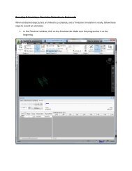
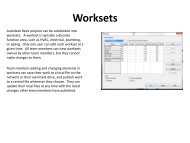
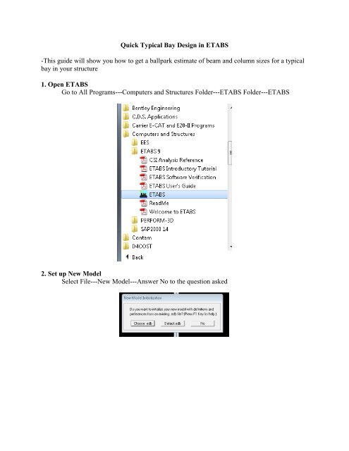
<strong>Quick</strong> <strong>Typical</strong> <strong>Bay</strong> <strong>Design</strong> <strong>in</strong> <strong>ETABS</strong>-<strong>This</strong> <strong>guide</strong> <strong>will</strong> <strong>show</strong> you how to get a ballpark estimate of beam and column sizes for a typicalbay <strong>in</strong> your structure1. Open <strong>ETABS</strong>Go to All Programs---Computers and Structures Folder---<strong>ETABS</strong> Folder---<strong>ETABS</strong>2. Set up New ModelSelect File---New Model---Answer No to the question asked
3. Edit Build<strong>in</strong>g Plan Grid System and Story Data Def<strong>in</strong>itionNote the units selected.For this example, I <strong>will</strong> just be do<strong>in</strong>g a one story bay. Input as follows:
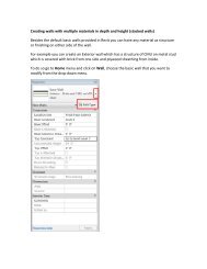
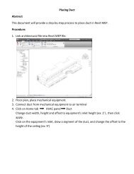
4. You can then select the Structural System that you are design<strong>in</strong>g. <strong>This</strong> example <strong>will</strong><strong>show</strong> you how to do a Steel System with Steel Deck.After edit<strong>in</strong>g the dimension values, click steel deck.You can now edit the floor system to your typical bay.
Note: You can specify Superimposed Dead Load and Live Load <strong>in</strong> this step or later. Ichose to specify it later.Then Click Ok and then Ok aga<strong>in</strong> and you’re bay should appear on screen similar tobelow.
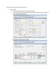
5. Edit your Deck DimensionsGo to Select---by Area Object Type---Floor---Click OkYour floor deck should be selectedNext, Go to Assign---Shell/Area---Wall/Slab/Deck Section---Choose Deck 1---ModifySectionThe w<strong>in</strong>dow below should appear.Edit the <strong>in</strong>formation to correspond with the floor deck that you have designed.
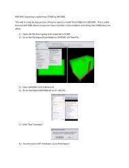
7. Run AnalysisGo to Analyze---Run AnalysisNow, we are ready for the design procedure.8. Set <strong>Design</strong> OptionsGo to Options---Preferences---Steel Frame <strong>Design</strong>Now you can set design parameters and the design code you would like to use.
Also set the design options for a composite steel design follow<strong>in</strong>g the same procedure.Note you can remove camber options <strong>in</strong> the deflection tabBy do<strong>in</strong>g this, you can compare design results accurately between the two systems.
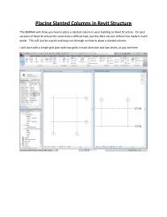
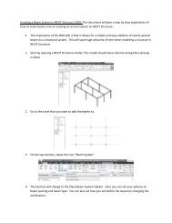
9. <strong>Design</strong> StructureGo to <strong>Design</strong>---Steel Frame <strong>Design</strong>---Start <strong>Design</strong>/Check of SystemThe sizes <strong>will</strong> now appear on the structure like belowYou can then follow the same procedure to do a composite steel design and compare your resultsConclusionYou now have a basic range of sizes to expect when design<strong>in</strong>g your structureIt is recommended that you do calculations by hand or by us<strong>in</strong>g Excel, to ensure your designsatisfies code requirements.