technical service guide new 30" xl44™ series ... - Appliance Blog
technical service guide new 30" xl44™ series ... - Appliance Blog
technical service guide new 30" xl44™ series ... - Appliance Blog
- No tags were found...

You also want an ePaper? Increase the reach of your titles
YUMPU automatically turns print PDFs into web optimized ePapers that Google loves.
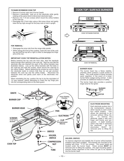
TO RAISE OR REMOVE COOK TOPRemove 4 burner caps and 4 burner headsRemove 4 electrodes (pull up on the electrode while gentlyrotating at the same time) & disconnect electrode leads.Remove (12) T-15 torx screws which mount the orifice holdersto the cook topDisengage the 2 front clips using a flat screw driver and gentlyraise the top high enough for the prop rods to hold it upright.COOK TOP / SURFACE BURNERSCOOK TOP RAISED POSITIONFOR REMOVAL:Disengage the prop rods from the range slide panelsWhile raising the front of the cooktop, lower the rear of the cooktop and shift the top left or right in order to disengage the hingepins at the rear.IMPORTANT COOK TOP REINSTALLATION NOTES:Before lowering the top onto the front clips, feed the electrodeleads through each opening in the cook top. Next be sure that theelectrode clips are inserted into each of the orifice brackets (seeillustration below). Line up the orifice brackets with the holes inthe cook-top and start the screws, which secure the cook-top tothe orifice holders. Before tightening the screws be sure to checkthe electrode leads to ensure that they do not get pinchedbetween the cook top and the orifice holder. Reconnect theelectrode wires and gently push each of the electrodes intoposition.When reinstalling the top, position the top to be the equivalent of1/2 way lowered, before attempting to insert the top hinge pinsinto the corresponding slots on the back-guard.COOK TOP REMOVALBURNER HEADThe burner head has a flame stabilitychamber which protects a small pocket offlame. This small pocket of flame providesquick reignition, in the event of a minorburner flame outage during simmer. It alsoprovides an additional measure of safety.The burner head also provides a positivetarget area for the Ignitor.GRATEBURNER CAPFlame StabilityChamberBURNERHEADIGNITORBURNER HEADSCREWST-15 TorxScrewsCOOK TOPORIFICEHOLDER,ORIFICEPANCOMPRESSIONNUTTUBEELECTRODECLIP(CompressionSleeve)HOLDER, ORIFICEELECTRODE MOUNTINGEach electrode pushes into aclip (compression sleeve),which mounts to each of thefour orifice holders. Thisallows the electrode to beremoved without lifting thetop. To remove theelectrode, grasp it with yourfinger and thumb and pullupward. A slight twistingaction may help in removingthe electrode. All fourelectrodes MUST beremoved prior to lifting thetop.To improve alignment and stability the 4 burner orifice brackets(holders) have been modified. The brackets are mounted to thecooktop with three "T-15" torx screws. The screw heads arelocated under the burner head. These screws MUST beremoved prior to lifting the cooktop. The rigid mounting systemensures proper alignment of the orifice for gas to be injectedinto the burner head.– 10 –