Aviosys IP Power Switch 9258-PRO Manual - Openxtra
Aviosys IP Power Switch 9258-PRO Manual - Openxtra
Aviosys IP Power Switch 9258-PRO Manual - Openxtra
- No tags were found...

You also want an ePaper? Increase the reach of your titles
YUMPU automatically turns print PDFs into web optimized ePapers that Google loves.
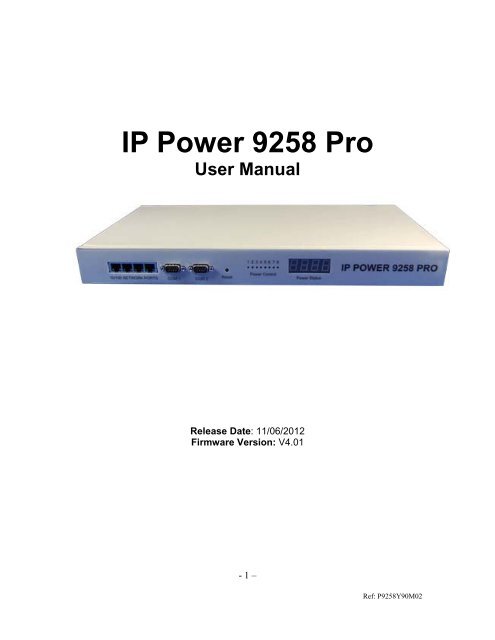
<strong>IP</strong> <strong>Power</strong> <strong>9258</strong> ProUser <strong>Manual</strong>Release Date: 11/06/2012Firmware Version: V4.01- 1 –Ref: P<strong>9258</strong>Y90M02
Warning: Any changes made to this equipment without permission may cause damages to thedevice!IMPORTANT NOTICE1. <strong>IP</strong> <strong>Power</strong> <strong>9258</strong> Pro was designed for indoor use, we carry no responsibility for possible damages causedby outdoor use, especially in the rain.2. Please use the power adapter provided by the dealer, we carry no responsibility for the possible damagefrom using power adapters not .4. Do not shake the <strong>IP</strong> <strong>Power</strong> <strong>9258</strong> Pro in any fashion5. Please contact the dealer If <strong>IP</strong> <strong>Power</strong> <strong>9258</strong> Pro is not working properly.Copyright © 2011 All rights reserved. No part of this publication may be reproduced, stored in a retrievalsystem, or transmitted in any form or by any means, electronic, mechanical, photocopying, recording orotherwise, without the prior written consent of us.All trademarks and products mentioned in this document are the properties of us.- 2 –Ref: P<strong>9258</strong>Y90M02
Table of Content1.) AVIOSYS INTRODUCTION ............................................................................ 5Introduction .................................................................................................................................................. 5Minimum System Requirements ................................................................................................................. 52.) <strong>PRO</strong>DUCT OVERVIEW ................................................................................... 6Features ......................................................................................................................................................... 6Specification .................................................................................................................................................. 6Package Contents ......................................................................................................................................... 63.) HARDWARE DESCR<strong>IP</strong>TION .......................................................................... 74.) QUICK START GUIDE .................................................................................... 8Quick Hardware Setup ................................................................................................................................ 8Quick Device Setup....................................................................................................................................... 85.) HARDWARE SETUP ...................................................................................... 96.) SOFTWARE SETUP ....................................................................................... 9Installing <strong>IP</strong> <strong>Power</strong> Software ......................................................................................................................10Using <strong>IP</strong> Edit ................................................................................................................................................10<strong>IP</strong> Service......................................................................................................................................................147.) HARDWARE INTERFACE ............................................................................ 15Hardware Reset ...........................................................................................................................................15Serial Port Control ......................................................................................................................................15Reading the LED Panel ...............................................................................................................................15Reading the VC Monitor .............................................................................................................................15- 3 –Ref: P<strong>9258</strong>Y90M02
How to Replace Fuse ...................................................................................................................................168.) WEB INTERFACE ......................................................................................... 17Connection to your Device ..........................................................................................................................17The Control Console....................................................................................................................................18<strong>Power</strong> Setup .................................................................................................................................................18<strong>Power</strong> Controls .........................................................................................................................................18VC Config.................................................................................................................................................20VC Monitor...............................................................................................................................................20System Configuration ..................................................................................................................................21System Setup ............................................................................................................................................21DDNS .......................................................................................................................................................22E-mail .......................................................................................................................................................23Schedule Ports 1-4 & Ports 5-8.................................................................................................................24<strong>IP</strong> Service ..................................................................................................................................................25Ping ...........................................................................................................................................................26Network Wakeup ......................................................................................................................................28Change Password ......................................................................................................................................28Firmware Update ......................................................................................................................................28Time Change .............................................................................................................................................299.) CONTROLLING THE DEVICE ...................................................................... 30CGI HTTP Commands ...............................................................................................................................30Set <strong>Power</strong> Command ................................................................................................................................30Set <strong>Power</strong> Delay Command ......................................................................................................................30Set Name Command .................................................................................................................................31Get Name Command ................................................................................................................................31Get Firmware Version Command .............................................................................................................31Get Time Command .................................................................................................................................32Set Time Command ..................................................................................................................................32Set Device Gateway Command ................................................................................................................32Set Device DNS Command ......................................................................................................................33Turn DHCP ON/OFF ................................................................................................................................33View Log Command.................................................................................................................................33Serial Com (RS-232) Control......................................................................................................................35Com1 ........................................................................................................................................................35Com2: High speed ....................................................................................................................................36SNMP ............................................................................................................................................................39Initial Setup: .............................................................................................................................................39SNMP MIB ...............................................................................................................................................4010.) XML FUNCTIONALITY ............................................................................... 4111.) FREQUENTLY ASKED QUESTIONS (F.A.Q)............................................ 43- 4 –Ref: P<strong>9258</strong>Y90M02
1.) <strong>Aviosys</strong> IntroductionIntroductionThe <strong>Aviosys</strong> <strong>9258</strong> Pro was designed for ease of use in mind. With its robust design to user friendly features,the <strong>9258</strong> Pro is a necessary commodity to the server room. <strong>Aviosys</strong> being one of the leaders in <strong>IP</strong> <strong>Power</strong>solutions built this device to provide high quality power control at a fraction of the price the competitors offer.With 8 output ports, a Voltage and current sensor, this device will provide information needed to make sureyour servers are running efficiently.Minimum System RequirementsOperating Systems: WINDOWS Operating Systems (IE5.0+SPIRJ45 LAN & Internet HUB & <strong>Switch</strong>Internet (For remote access) or Ethernet Network (Internal Network use) with some type of Internetconnection, (i.e. ADSL, Cable, Dial up or any other forms of Internet service)- 5 –Ref: P<strong>9258</strong>Y90M02
2.) Product OverviewFeatures1. Dual <strong>Switch</strong> Circuit Design for safety and protection2. Voltage, & Current monitoring system3. 4 Port HUB function4. Auto-ping (Watch dog) Device Auto Restart / Reboot.5. Critical Voltage Detector for Automatic Device Protection6. Supports: TCP/<strong>IP</strong>, Http API, Web Server, SMTP , SNMP & TRAP,DHCP , DDNS, CNT, XML7. 8 <strong>Power</strong> control output8. 2 Main power inputs.9. 2 RS232 port with one Hi-Speed Information Transfer10. Design Pressure System: Prevent interference with power noise design. (Second stageisolation)11. Scheduler System for date sensitive control12. Log Capability13. Http commands and RS232 SDK commands for integration purposes.14. CNT Technology: No Port Forwarding Needed15. <strong>IP</strong> Service: Easily Find your device on the internet without having to remembercomplicated <strong>IP</strong>’s16. Light Aluminum DesignSpecification1. Input <strong>Power</strong> Voltage: 90-240 VAC2. Input Frequency: 50/60 Hz full range3. Dimension: 440x235x40 mm 1.8kg4. Reliability testing Certification MBTF 200,000 hrs +5. Operating temperature range: 0 ~ 50 degrees Celsius.Package Contents<strong>9258</strong> Pro Unit x 1<strong>9258</strong> Pro Installation CDExtra Fuse x 1- 6 –Ref: P<strong>9258</strong>Y90M02
3.) Hardware Description4 Port Ethernet Hub:2 Serial Ports:Connect up to 4 separate devices with the builtin hub.Serial Port 1: Regular SpeedSerial Port 2: Hi-Speed transferTo reset to original manufacture settings, holdReset Button:down the reset button with a pen or a pin for 15seconds until will hear a long beep sound.7 Segment Led Indicator: The indicator will show two sets of Information.<strong>Power</strong> Status Indicator:The <strong>Power</strong> Status indicator8 Output <strong>Power</strong> Ports: Connect up to 8 separate devices that will becontrolled by the <strong>9258</strong> Pro. Ports 1-42 Input <strong>Power</strong> Ports: The input power sends power to the 2 sets of<strong>9258</strong>.The 2 <strong>Power</strong> switch turns on the input power2 <strong>Power</strong> <strong>Switch</strong>:Ports 1-4: <strong>Switch</strong> 1 Ports 5-8 <strong>Switch</strong> 2Replaceable FuseTYPE:U/C GFE 10A 250V (PF)- 7 –Ref: P<strong>9258</strong>Y90M02
4.) Quick Start GuideQuick Hardware Setup*Before you plug in the device make sure you have the appropriate input plugs.* For 220-250V, please use power cable that can support 10A current.Max Output Current: (total of each four outlets) 10A, (each outlet) 6A.* For 100-120V, please use power cable that can support 15A current.Max Output Current: (total of each four outlets) 15A, (each outlet) 6A1.) Make sure that all the package contents are included, if anything is missingplease contact the store.2.) Plug the RJ45 (Ethernet Cable) from your router or modem to any of the 4 portson the <strong>9258</strong> Pro.3.) Plug in the Input <strong>Power</strong> Plugs into the device and then into the wall of yourdevice.4.) Plug in the devices that you want to control in the output ports of the <strong>9258</strong> ProQuick Device SetupUsing <strong>IP</strong> Edit1.) Click on the REF button, and wait a few seconds. <strong>IP</strong>Edit willautomatically detect the network settings and setup the device.2.) Once settings have been detected hit the apply button to apply the new settings.3.) Hit yes to confirm and Enter the login and password for the Device to Approvechanges- 8 –Ref: P<strong>9258</strong>Y90M02
4.) Then hit the rescan button on <strong>IP</strong>Edit to confirm the changes have been made.5.) Once you have found your device double click on the device and the internetexplorer will pop up and ask for your login information.6.) Type in your password & login and the device is ready to use.* Remember that to access your device from the outside network, you will need to portforward the <strong>IP</strong> Address of your device.5.) Hardware Setup1.) Connect the <strong>IP</strong> <strong>Power</strong> Pro to a HUB or Router with a RJ45 network cable.2.) Connect the HUB or Router to the internet (May through ADSL/XDSL modem).3.) Connect the power adapter to the <strong>IP</strong> <strong>Power</strong> <strong>9258</strong> Pro.4.) Connect the power adapters of under control electric equipment to the corresponding out portof <strong>IP</strong> <strong>Power</strong> <strong>9258</strong>-Pro.Turn on your computer and the power adapter of <strong>IP</strong> <strong>Power</strong> <strong>9258</strong>-Pro* For 220-250V, please use power cable that can support 10A current.Max. output current: (total of each four outlets) 10A, (each outlet) 6A.* For 100-120V, please use power cable that can support 15A current.Max. Output current: (total of each four outlets) 15A, (each outlet) 6A6.) Software SetupThe software for the device is located on the Media Link-<strong>IP</strong> Family CD that came with the device.<strong>IP</strong> <strong>Power</strong> Pack is located on the main page of the CD. Please follow the directions carefully andinstall the necessary filesThe <strong>IP</strong> <strong>Power</strong> Necessary Software:* <strong>IP</strong>Edit : For search our <strong>IP</strong> product , access, modify basic configurations of <strong>IP</strong> POWER <strong>9258</strong>DS.* <strong>IP</strong> POWER Center : Own software for CNT and multiple <strong>IP</strong> power to control in onesoftware .- 9 –Ref: P<strong>9258</strong>Y90M02
Installing <strong>IP</strong> <strong>Power</strong> Software1.) First place the Media Link-<strong>IP</strong> Family CD that came with your device into your CD/DVDRom drive. The CD should auto run but if it does not go to the CD/DVD Rom drive andselect the file “autorun.html”.2.) Once the CD has started, go to the <strong>IP</strong> <strong>Power</strong> section and click and install the following:<strong>IP</strong>edit:<strong>IP</strong> Family Program used to search, access, modify basic configurations of <strong>IP</strong> Family products.<strong>IP</strong> <strong>Power</strong> Center:Multiple <strong>IP</strong> <strong>Power</strong> device manager to control the ON and OFF of the managed devices. (For<strong>IP</strong> <strong>Power</strong> <strong>9258</strong> Ping , 9280, 9211, 9222.)IOTracker:Device to Device control with Firewall bypass technology.(For <strong>IP</strong> <strong>Power</strong> 9212 Delux / 9211 / 9222 Versions 1.12 and later.)3.) Once installation is complete please double click the <strong>IP</strong>Edit to configure and search foryour device.Using <strong>IP</strong> Edit<strong>IP</strong>Edit is a search tool designed to setup and access the device.It comes with the <strong>IP</strong> Service feature which searches for the device easily without having toremember long complicated <strong>IP</strong> addresses. Instead, this technology allows the user to use a namemethod to find his or her device through the internet. .Please make sure you have the most updated version of <strong>IP</strong>Edit. Contact yourdistributor to provide you with the newest updated <strong>IP</strong>Edit.1.) After correctly installing the <strong>IP</strong>Edit software, double click on the <strong>IP</strong>Edit icon to run theprogram.- 10 –Ref: P<strong>9258</strong>Y90M02
2.) Open <strong>IP</strong> Edit and any device in the same network should automatically be detected andlisted in the local devices sections. The devices will need to be setup correctlythrough <strong>IP</strong>Edit so that you can properly access the device.3.) Setup the Device:All devices will need to be on the same network if not the device cannot be accessed and willnot be detected.a. Quick Easy Setup (Recommended)7.) Click on the REF button, and wait a few seconds. <strong>IP</strong>Edit willautomatically detect the network settings and setup the device.8.) Once settings have been detected hit the apply button to apply the new settings.- 11 –Ref: P<strong>9258</strong>Y90M02
9.) Hit yes to confirm and Enter the login and password for the Device to Approvechanges10.) Then hit the rescan button on <strong>IP</strong> Edit to confirm the changes have been made.b. Custom Setup (Advance Users)1.) Highlight the device on the local devices section and on the right side of <strong>IP</strong>Edit allnetwork information on the device will be displayed.If the device is not on the same network a Red Exclamation markin the <strong>IP</strong> Network information sectionwill appear- 12 –Ref: P<strong>9258</strong>Y90M02
2.) To setup the device, type in the correct Gateway and <strong>IP</strong> Address.The gateway address:Gateway Address: The gateway address can be obtained in Windows under thenetwork connections page<strong>IP</strong> Address: Make sure the first 3 sections of the <strong>IP</strong> Address matches the gatewayaddress.Example: Gateway Address – 192.168.1.1 <strong>IP</strong> Address – 192.168.1.xxx3.) Once the Default Gateway information has been obtained, enter the correctinformation into <strong>IP</strong>Edit and hit the submit button.- 13 –Ref: P<strong>9258</strong>Y90M02
4.) Then hit the rescan button on <strong>IP</strong> Edit to confirm the changes have been made<strong>IP</strong> ServiceHow to use <strong>IP</strong> Service on <strong>IP</strong> Edit:<strong>IP</strong> service allows the user to directly connect to his / her device through the internet withouthaving to remember long confusing <strong>IP</strong> Address. Instead with this <strong>IP</strong> Service Technology, the useronly has to remember the name of the device that the user has selected. Then the user canconnect to <strong>IP</strong> Service, type in the device name, and connect directly to the device.First if you have de-activated <strong>IP</strong> Service on your device make sure you re-enable it. (Refer to yourmanual if you have questions on How to activate <strong>IP</strong> Service)1.) Open <strong>IP</strong>Edit, the device will show up in the Local Device Section. If you have notselected a name for the device, please refer to the section on the manual labeled:“Naming your device”.2.) To start <strong>IP</strong> Service, Hit the green connect button on the top of <strong>IP</strong>Edit.- 14 –Ref: P<strong>9258</strong>Y90M02
RMS Current 2 (Total Current for port 5-8)How to Replace Fuse1.) The fuse is located between the power switch and the power input plugs.2.) Carefully remove the fuse holder with a flat screwdriver.3.) The fuse can be purchased at most electrical storesModel: U/C GFE 10A 250V (PF)- 16 –Ref: P<strong>9258</strong>Y90M02
8.) Web InterfaceConnection to your DeviceOnce you have the <strong>9258</strong> Pro setup correctly.Open <strong>IP</strong>Edit and double click on your <strong>IP</strong> <strong>Power</strong> <strong>9258</strong> Pro.A Internet Explorer browser screen pop up with the login screen for the <strong>9258</strong> Pro.Default <strong>IP</strong>: 192.168.1.100 (When <strong>9258</strong> Pro is connected to PC directly)Default Login: AdminDefault Password: 12345678- 17 –Ref: P<strong>9258</strong>Y90M02
The Control ConsoleThe Right Panel of the Web Interface controls the functionality and setup of the <strong>IP</strong> <strong>Power</strong> <strong>9258</strong>Pro.<strong>Power</strong> Setup<strong>Power</strong> ControlsThe <strong>Power</strong> Controls setting allows you to control the devices that are connected to the <strong>9258</strong> Pro.- 18 –Ref: P<strong>9258</strong>Y90M02
Name: The name field allows you to enter a name of the <strong>Power</strong> that you are controlling. Simpletype in the name of the device next to the outlet that it is connected to, then hit apply.Control: Control allows the user to actively control the device on each port. To turn off or turn onthe device, select the control you want then hit the apply buttonTimer: The timer allows you to turn On or Off your device with a delay. Please view the examplebelow:<strong>Power</strong> 1: The device will turn on when you hit the apply button and after 5 seconds the devicewill be turned off.<strong>Power</strong> 2: The device will be off and when you hit apply after 10 seconds then the device will turnon.- 19 –Ref: P<strong>9258</strong>Y90M02
VC ConfigThe VCT (Voltage & Current ) config allows you to configure the critical points of the Unit Voltage,RMS Current 1, RMS Current 2.When that critical point has been reached the <strong>9258</strong> Pro will respond by sending a e-mailnotification and it safely shut down.Unit Voltage:If the total voltage of the <strong>9258</strong> Pro reaches the critical that has been set the device will safely shutdown.RMS Current 1 (Ports 1-4)The RMS Current 1 is the total number of AMPS that is used for ports 1-4. If the total Ports AMPexceeds the Critical the device will safely shut downRMS Current 2 (Ports 5-8)The RMS Current 2 is the total number of AMPS that is used for ports 5-8. If the total Ports AMPexceeds the Critical the device will safely shut down.VC MonitorThe VCT monitor is the webpage that monitors the status of the VC. It will give you the actualUnit Voltage, RMS Current 1 & RMS Current- 20 –Ref: P<strong>9258</strong>Y90M02
System ConfigurationSystem SetupThe System Setup page is where you would configure the basic <strong>IP</strong> information needed for thedevice to work properly<strong>IP</strong> Address: The <strong>IP</strong> Address of the <strong>9258</strong> Pro can be specified here. If you are using a hub orrouter, the <strong>IP</strong> address may be selected for you already. Otherwise you can manually select the <strong>IP</strong>Address here.Subnet Mask: The Subnet Mask Address of the <strong>9258</strong> Pro can be specified here. If you are usinga hub or router, the <strong>IP</strong> address may be selected for you already. Otherwise you can manuallyselect the <strong>IP</strong> Address here.Default Gateway: The Default Gateway is given by a router or hub and this is where thatinformation would be specified.DNS: The DNS is the Domain Name Server. This information can be obtained by contacting theISPDHCP Client: The DHCP client allows the <strong>9258</strong> Pro to use DHCP to obtain the <strong>IP</strong> Informationfrom a Hub or Router.Beeper: The Beeper turns on/off the beeper sound from the <strong>9258</strong> Pro. When commands are senta beep sound will appear.Http Command Verification: The HTTP Verification turns on or off the HTTP Command mode.This mode allows you to send commands directly to the device via internet without having toenter the device.- 21 –Ref: P<strong>9258</strong>Y90M02
Device Name: In this section you can change the name of the <strong>9258</strong> pro for easier identificationpurposes. It is also a way to find your device using <strong>IP</strong> Service.Release Version: Displays information on the Firmware version and release date.DDNSThe DDNS section allows you to setup the <strong>9258</strong> Pro with a DDNS server (i.e. www.dyndns.com).The the server has been setup correctly, enter the necessary information into the <strong>9258</strong> Pro DDNSsettings.DDNS Server <strong>IP</strong>: Input <strong>IP</strong> Address of the DDNS server.Your Domain: Type in the Domain Name that you selected for your DDNS serverDDNS Username: Enter the DDNS UsernameDDNS Password: Enter the corresponding Password for your DDNS accountEnable DDNS: Select Enable or Disable to turn on or off DDNS settings for the <strong>9258</strong> ProProxy Enable: Select enable or disable if any proxy servers are used.Proxy <strong>IP</strong>: Enter the proxy server <strong>IP</strong> Address of the proxy server here.Proxy Port: Enter Port of the proxy server- 22 –Ref: P<strong>9258</strong>Y90M02
E-mailThe <strong>9258</strong> Pro has an e-mail function that can be used in various scenarios and conditions. Whena power port is activated or deactivated, the device will send an email.When the scheduler is used the device will also send emails when ports are activated ordeactivated.To send out mail successfully , please do set the DNS correctly . You can check with your ISPfor correct DNS information.Smtp Server: Input the server name of the mail server.SmtpPort: Input the outgoing Server PortPop 3 Server: Input the incoming pop 3 server informationUsername: Enter E-mail usernamePassword: Enter E-mail password ( no longer than 8 characters) .Sender: Enter Sender Email AddressReceiver 1-3: Enter up to 3 receiversSubject: Enter the email Subject lineMail Body: Enter Email Body information.- 23 –Ref: P<strong>9258</strong>Y90M02
Schedule Ports 1-4 & Ports 5-8The scheduler function allows you automatically control the device(s) without having to login. Thisfunction allows you to turn on or turn off, cycle power of your devices at scheduled times. To usethe this function some key parameters must be set correctly.<strong>Power</strong>Date: Input the date for the device to activate power controls. Format: (YYYY-MM-DD)Time: Enter the exact time of when the device will be activated on. Format: (HH:MM:SS)Note: Hour is based on a 24hr military time.- 24 –Ref: P<strong>9258</strong>Y90M02
Frequency: Select the number of times this event will be activated (Disable, Just Once, Everyday,Workdays, Weekend)Disable: Disables the schedulerJust Once: Activates the schedule only onceEveryday: Activates everyday until schedule has been deactivatedWorkdays: Activates every week from Monday – Friday until deactivatedWeekend: Activates every week on Saturday & Sunday until deactivated<strong>Power</strong> On / Off: Set the power to On or Off when the scheduler is activatedSystem Startup <strong>Power</strong> Default Value: When <strong>9258</strong> Pro starts up, this setting will set the <strong>Power</strong>to On or Off as the default value.<strong>IP</strong> ServiceThe <strong>IP</strong> Service functionality allows your <strong>9258</strong> Pro to easily be found on the internet by using <strong>IP</strong>Service. This function allows you to search for your device on <strong>IP</strong>Edit without having to rememberlong <strong>IP</strong> Addresses. Instead all you need is the name of your <strong>9258</strong> Pro and you can access it there.Refer to Page 13 of the manual on how to use <strong>IP</strong> ServiceOn / Off: This allows you to turn on or off <strong>IP</strong>Edit. By default this function is enabledServer Address: The <strong>IP</strong> Service Server address by default is 220.135.169.136. Please contactyour distributor for information on how to setup your own <strong>IP</strong> Service*Note: To use <strong>IP</strong> Service Make sure that you have port forwarded the <strong>IP</strong> Address of the <strong>9258</strong> Pro.IF not you will not be able to access your device.- 25 –Ref: P<strong>9258</strong>Y90M02
PingThe Auto-ping functionality allows the <strong>9258</strong> Pro to check if the device have malfunctioned orneeds to be restarted. If the device is no working correctly the <strong>9258</strong> Ping will activate the actionthat you have selected to reinstate the state of the deviceOutlet: A description of which on let to use Ping functionEnable: Disable or Enable ping settingsPing Address: Specify the <strong>IP</strong> Address to PingPing Failures: The number of ping failures before the Action is activated.Action Delay (Seconds): When Ping Failures is reached the number of seconds delay beforeaction is activated.(I.E some systems or computers that require a shut down time)Startup Delay (Seconds): The number of seconds it takes the attached devices to startup. Oncethose devices start, the Start up Action will be activated to continue pinging or stoppinging.Start up Action: After start up Delay has been reached the start up action will either ContinuePinging or Stop PingingAction: When the number of Ping Failures have been reached. The <strong>9258</strong> will eitherPing Time Interval (Seconds): The number of seconds between each ping- 26 –Ref: P<strong>9258</strong>Y90M02
Ping Response Time (Milliseconds): The number of milliseconds the device will wait for aresponse from the pinged device if no ping is detected within this time it will be considered a pingfailure.Please view the example below for more details:In the picture above:1.) <strong>Power</strong>1 Ping function is enabled2.) The <strong>9258</strong> Pro will ping the web address www.sample.com3.) If there is a response within the Ping Response Time the <strong>9258</strong> Pro will sendanother ping signal the set Ping Time Interval which is 3 seconds for thisexample.4.) If the <strong>9258</strong> Pro does not receive a response from the device it will constitute aPing Failure.5.) After 3 consecutive failure the device will go to the Action Delay section. In thiscase the device will delay for 3 seconds.6.) When action delay has been reached the Action will be set off. Here we have setthe <strong>9258</strong> Pro to Reset the device.7.) Once the device has been reset the <strong>9258</strong> will go into Startup Delay mode. In thiscase it is 3 seconds.8.) After the startup delay mode has been reached the <strong>9258</strong> will check the StartupAction whether to continue or stop pinging the device. Here we have it set toContinue.9.) Then the process starts all over.- 27 –Ref: P<strong>9258</strong>Y90M02
Network WakeupThe network wakeup function is used to boot up a computer that has the Wake on Lanfunctionality. Just enter the MAC address of the target computer and the <strong>9258</strong> Pro will be able toturn on the device.Change PasswordThe change password page allows you to change your password for the <strong>9258</strong> Pro. To change thepassword:10.) Enter the current password.11.) Type in the New Password12.) Confirm New PasswordFirmware UpdateFollow the instructions carefully and update with caution.1.) Click the update Button.- 28 –Ref: P<strong>9258</strong>Y90M02
2.) Wait for the continue button to load properly. Then hit the continue button.3.) Once you have clicked continue the <strong>9258</strong> Pro will take you to the update page.4.) Browse for the update file5.) Hit the update button and wait for as least 1 minute for the upgrade to complete.Time ChangeThe change time feature allows you to change time of your device by setting the time or selectinga NTP server.Set Date and TimeTo set the time of the device enter the Date/ Time withDate: YYYY-MM-DDTime:24HH-MM-SSNTP ServerThe NTP Server allows the <strong>9258</strong> Pro to check with a NTP (Network Time Protocol) to constantlykeep the internal clock of the device updated.- 29 –Ref: P<strong>9258</strong>Y90M02
9.) Controlling the DeviceCGI HTTP CommandsCGI Commands allow you to easily integrate the <strong>9258</strong> Pro with other systems and programs.Please read the instructions carefully on how to use the Http:// CommandsTo use http:// Commands open up a web browser and type in the command that you would like touse.The command structure looks like thishttp://xxx.xxx.x.xxx/set.cmd?user=USER+pass=PASSWORD+cmd=COMMANDSet <strong>Power</strong> CommandCommandhttp://<strong>IP</strong>/set.cmd?cmd=setpower+p6x=y+p6x=y+p6x=y+p6x=y+p6x=y+p6x=y+p6x=y+p6x=yx = 1~8 means output numbery = 1/ 0 means power on/off . 1 means power ON , 0 means power offExample :http://<strong>IP</strong>/set.cmd?cmd=setpower+p61=0+p62=1+p63=0+p64=1+p65=0+p66=+p67=0+p68=means turn OFF of output 1,3,5&7means turn ON of output 2,4,6&8Set <strong>Power</strong> Delay CommandCommandhttp://<strong>IP</strong>/set.cmd?cmd=setpower+p6x=y+p6xn=0+t6x=Ax = 1~8 means output numbery = 1/ 0 means power on/off . 1 means power ON , 0 means power offA = 1~9999 means delay second .Example :Turn Output #1 as power on and then turn off after 30 secondshttp://192.168.1.123/set.cmd?cmd=setpower+p61=1+p61n=0+t61=30- 30 –Ref: P<strong>9258</strong>Y90M02
Read voltage , current 1 ( port 1-4 ) and current 2 ( port 5-8 )http:// <strong>IP</strong> /set.cmd?user=admin+pass=12345678+cmd=getvctGet response as : VC1C2T : 223..10.31.44V =223 means Voltage =223VC1 = 10 means Total Current of port 1 to 4 = 1.0ampC2 = 31 means Total Current of port 5 to 8 = 3.1ampT= 44 means Temperature is 44 degree CelsiusSet Name CommandCommand:setportn+ch=port number+portn=name of porthttp://xxx.xxx.x.xxx/set.cmd?user=admin+pass=12345678+cmd=setportn+ch= PortNumber+portn= Name of PortExample:http://192.168.1.39/set.cmd?user=admin+pass=12345678+cmd=setportn+ch=1+portn=test1Response Message: Port1Name_Set_OkGet Name CommandCommand:getportn+ch=port number+portn=name of portFormat: http://xxx.xxx.x.xxx/set.cmd?user=admin+pass=12345678+cmd=getportn+ch=PortNumber+portn=Name of PortExample:http://192.168.1.39/set.cmd?user=admin+pass=12345678+cmd=getportn+ch=1+portnResponse Message: Port1Name:test1Get Firmware Version CommandCommand:GetVersion- 31 –Ref: P<strong>9258</strong>Y90M02
setfactory+gateway=xxx.xxx.x.xxx+confirm=factoryonlyFormat:http:192.168.1.100/Set.cmd?user=admin+pass=12345678+cmd=setfactory+gateway=xxx.xxx.x.xxx+confirm=factoryonlyExample:http:192.168.1.100/set.cmd?user=admin+pass=12345678+cmd=setfactory+gateway=192.168.1.1+confirm=factoryonlyResponse Message: Gateway: 192.168.1.1Set Device DNS CommandCommand:setfactory+dns=xxx.xxx.x.xxx+confirm=factoryonlyFormat:http://xxx.xxx.x.xxx/set.cmd?user=admin+pass=12345678+cmd=setfactory+dns=xxx.xxx.x.xxx+confirm=factoryonlyExample:http:192.168.1.100/set.cmd?user=admin+pass=12345678+cmd=setfactory+dns=202.103.225.68+confirm=factoryonlyResponse Message: DNS:202.103.225.68Turn DHCP ON/OFFCommand:setfactory+dhcp=x+confirm=factoryonlyFormat:http://xxx.xxx.xxx/set.cmd?user=admin+pass=12345678+cmd=setfactory+dhcp=(0=off1=on)+confirm=factoryonlyExample:http:192.168.1.100/set.cmd?user=admin+pass=12345678+cmd=setfactory+dhcp=1+confirm=factoryonlyResponse Message:DHCP: 0orDHCP: 1View Log CommandCommand:getlog+num=01~50- 33 –Ref: P<strong>9258</strong>Y90M02
Format:http://xxx.xxx.x.xxx/set.cmd?user=admin+pass=12345678+cmd=getlog+num=01~50Example:http://192.168.1.42/set.cmd?user=admin+pass=12345678+cmd=getversionLog No. 1 Newest LogLog No. 50 Oldest LogResponse Message:Sample Log:<strong>Power</strong>1:ON<strong>Power</strong>2:ON<strong>Power</strong>3:OFF<strong>Power</strong>4:OFF<strong>Power</strong>5:OFF<strong>Power</strong>6:OFF<strong>Power</strong>7:OFF<strong>Power</strong>8:ONSocket1:TurnOnSocket2:TurnOnSocket3:TurnOffSocket4:TurnOffSocket5:TurnOffSocket6:TurnOffSocket7:TurnOffSocket8:TurnOnLogNO.1 PortState:83-PortAct:ffTime:2008-12-16 17:02:54What this log shows:Status of <strong>Power</strong>s 1-8Status of Sockets 1-8Log NO.1<strong>Power</strong>: Represents the current status of the outlets.Sockets: Represents the last changed status of the outlets.- 34 –Ref: P<strong>9258</strong>Y90M02
Serial Com (RS-232) ControlCom1The Com1 allows you to read the status of the <strong>9258</strong> Pro. Information can be extracted throughthis port like an output1.) Use DB9 cable connect to the COM1 of PC and the RS232 of device2.) Execute WIN program "Hyper Terminal" : please go to " Start" / "program" /"Accessories" / "Communications" / "Hyper Terminal" .3.) Set the "Bits per second" as 19200 at COM1 (Must at COM1)- 35 –Ref: P<strong>9258</strong>Y90M02
4.) Turn off the device then turn it back on and the screen will display the following information:Com2: High speedThe Com2 port which is a high speed serial port which is a input port for the <strong>9258</strong> Pro via serialport.SetPort CommandThe SetPort utilizes a 16 base Hexadecimal to control the power ports of the <strong>9258</strong> Pro. Thiscommand is case sensitive please type in the commands very carefully.The SetPort=0xNnN = Represents Ports 5-8n = Represents Ports 1-4By using 16 base Hexadecimal you tell the device to turn on the different power ports.The SetPort command will need to be input in the Hyperterminal console like the picture below- 36 –Ref: P<strong>9258</strong>Y90M02
View the examples below for additional information.0 hex = 01 hex = 12 hex = 23 hex = 34 hex = 45 hex = 56 hex = 67 hex = 78 hex = 89 hex = 910 hex = A11 hex = B12 hex = C13 hex = D14 hex = E15 hex = FOther CommandsChanging Baud rateCommand:SetSerTxSt+StrFormat:http://xxx.xxx.xxx/set.cmd?user=admin+pass=12345678+cmd=setsertxst+str=testcom2- 37 –Ref: P<strong>9258</strong>Y90M02
Example:http://192.168.0.1/Set.cmd?user=admin+pass=12345678+cmd=setserbdrt+bd=57600Response Message:BaudRate:57600Input Command StringCommand:setsertxst+strFormat:http://xxx.xxx.xxx/set.cmd?user=admin+pass=12345678+cmd=setsertxst+str=testcom2Example:http://192.168.0.1/Set.cmd?user=admin+pass=12345678+smd=setsertxst+str=testcom2Response Message:Message will be displayed on the Hyperterminal console.Read Console CommandCommand:setserrxst+strFormat:http://xxx.xxx.xxx/set.cmd?user=admin+pass=12345678+cmd= setserrxstExample:http://192.168.0.1/set.cmd?user=admin+pass=12345678+cmd= setserrxstResponse Message:Command will return the input string that was entered in hyperterminalRefer to example belowStep 1:Type in a line into the Hyperterminal Console.- 38 –Ref: P<strong>9258</strong>Y90M02
In this example the text is helloCOM2Step 2:Type in the command to read hyperterminalhttp://192.168.1.42/set.cmd?user=admin+pass=12345678+cmd=setserrxstResults:The screen will display the words helloCOM2 on your internet explorer.To Erase the memory use the same Commandhttp://192.168.1.42/set.cmd?user=admin+pass=12345678+cmd=setserrxstand you will get the following message.SNMPInitial Setup:1.) Download Net-SNMP (http://www.net-snmp.org) and install thesoftware2.) Once the software has been installed Register the agent3.) Register the agent4.) Start the service- 39 –Ref: P<strong>9258</strong>Y90M02
SNMP MIBGet Status MIBPort 1: 1.3.6.1.4.1.92.59.2.1.0Port 2: 1.3.6.1.4.1.92.59.2.2.0Port 3: 1.3.6.1.4.1.92.59.2.3.0Port 4: 1.3.6.1.4.1.92.59.2.4.0Port 5: 1.3.6.1.4.1.92.59.2.5.0Port 6: 1.3.6.1.4.1.92.59.2.6.0Port 7: 1.3.6.1.4.1.92.59.2.7.0Port 8: 1.3.6.1.4.1.92.59.2.8.0Ex: snmpget -v 1 -c public 192.168.1.96 1.3.6.1.4.1.92.59.2.1.0Response: SNMPv2-SMI::enterprises.92.59.2.1.0 = INTEGER: 0Integer 0 = OffInteger 1 = OnGet Voltage MIB1.3.6.1.4.1.92.59.3.1.0Ex: snmpget -v 1 -c public 192.168.1.96 1.3.6.1.4.1.92.59.3.1.0Response: SNMPv2-SMI::enterprises.92.59.3.1.0 = INTEGER: 113- 40 –Ref: P<strong>9258</strong>Y90M02
Get Current MIB1.3.6.1.4.1.92.59.4.1.0Ex: snmpget -v 1 -c public 192.168.1.96 1.3.6.1.4.1.92.59.4.1.0Response: SNMPv2-SMI::enterprises.92.59.4.1.0 = INTEGER: 0Get Current 2 MIB1.3.6.1.4.1.92.59.4.2.0Ex: snmpget -v 1 -c public 192.168.1.96 1.3.6.1.4.1.92.59.4.2.0Response: SNMPv2-SMI::enterprises.92.59.4.2.0 = INTEGER: 0Get Temperature MIB1.3.6.1.4.1.92.59.5.1.0Ex: snmpget -v 1 -c public 192.168.1.96 1.3.6.1.4.1.92.59.5.1.0Response: SNMPv2-SMI::enterprises.92.59.5.1.0 = INTEGER: 51Set Port MIB1.3.6.1.4.1.92.59.2.1.0Port 1: 1.3.6.1.4.1.92.59.2.1.0Port 2: 1.3.6.1.4.1.92.59.2.2.0Port 3: 1.3.6.1.4.1.92.59.2.3.0Port 4: 1.3.6.1.4.1.92.59.2.4.0Port 5: 1.3.6.1.4.1.92.59.2.5.0Port 6: 1.3.6.1.4.1.92.59.2.6.0Port 7: 1.3.6.1.4.1.92.59.2.7.0Port 8: 1.3.6.1.4.1.92.59.2.8.0Integer 0 = OffInteger 1 = OnEx: snmpset -v 1 -c public 192.168.1.96 1.3.6.1.4.1.92.59.2.1.0 integer 1Response: SNMPv2-SMI::enterprises.92.59.2.1.0 = INTEGER: 110.) XML FunctionalityThe <strong>9258</strong> Pro supports XML. Before you can start using it you will need to enable it by using thehttp command:http://xxx.xxx.x.xxx/Set.cmd?user=admin+pass=12345678+CMD=EnablexmlOnce the XML is enabled you should see a message that says: EnableXML- 41 –Ref: P<strong>9258</strong>Y90M02
Once XML has been enabled to access the XML type in the command:http://xxx.xxx.x.xxx/info.xmlThe XML commands are listed below:http://xxx.xxx.x.xxx/info.xmlhttp://xxx.xxx.x.xxx/Set.cmd?user=admin+pass=12345678+CMD=Enablexmlhttp://xxx.xxx.x.xxx/Set.cmd?user=admin+pass=12345678+CMD=DisablexmlPlease view the XML output for reference.- 42 –Ref: P<strong>9258</strong>Y90M02
11.) Frequently Asked Questions (F.A.Q)Q1: How do I reset the device back to manufacturer default values?Ans: In the front panel of the <strong>9258</strong> Pro, there is a reset feature that will reset the device back tomanufacturer default settings. Take a pen or small pin, then press and hold for about 10-15seconds. Once you hear a single “beep” sound the device will be reset back to manufacturerdefaultDefault <strong>IP</strong>: 192.168.1.100 (When <strong>9258</strong> Pro is connected to PC directly)Default Login: AdminDefault Password: 12345678Q2: What can I do if I forget my password?Ans: In the login field enter the field1.) “super user”: do not enter the quotation marks and there is a space between super and user.2.) Then do not enter, a password and hit the submit button3.) Unplug the device and plug it back in.4.) Then use the default login and passwordDefault Login: adminDefault Password: 12345678For security concern , please do power reboot <strong>9258</strong> in 1 minutes after click submit as type "super user " in the username as loginQ3: What is dual switch technology?Ans: Dual <strong>Switch</strong> technology is an additional safety feature of the <strong>9258</strong> Pro. Unlike conventionalpower distribution units or remote power control units the <strong>9258</strong> Pro has a dual switch designwhich will completely cut off the power to the devices. Other designs which do not have thisfeature will may create a harmful environment that will affect the devices or the things around it.Below is a picture ofQ4: How come I can not connect to my device from an outside network?Ans: To use the device outside of LAN (Local Area Network. If a router is present you will have toport forward the Local <strong>IP</strong> Address of the <strong>9258</strong> Pro so that it could be reached by the outside world.Please refer to the manual on how to accomplish this task.- 43 –Ref: P<strong>9258</strong>Y90M02